Geometric Modeling in CAD
Geometric modeling in computer-aided design (CAD) is crucially done in three key ways: wireframe modeling, surface modeling, and solid modeling. Wireframe modeling represents objects by their edges, whereas surface modeling uses surfaces, vertices, and edges to construct components like a box. Each technique has its advantages and applications, from aerospace design to automotive manufacturing. Explore the nuances of these modeling methods to enhance your understanding of CAD.

Download Presentation

Please find below an Image/Link to download the presentation.
The content on the website is provided AS IS for your information and personal use only. It may not be sold, licensed, or shared on other websites without obtaining consent from the author.If you encounter any issues during the download, it is possible that the publisher has removed the file from their server.
You are allowed to download the files provided on this website for personal or commercial use, subject to the condition that they are used lawfully. All files are the property of their respective owners.
The content on the website is provided AS IS for your information and personal use only. It may not be sold, licensed, or shared on other websites without obtaining consent from the author.
E N D
Presentation Transcript
Geometric modeling is done in 3 principle ways: 1- Wire frame modeling 2- Surface modeling 3- Solid modeling
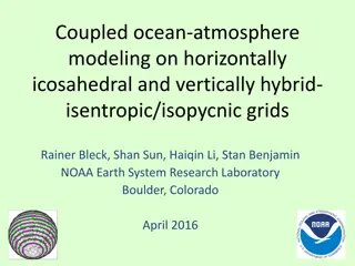
WIRE FRAME MODELING In wire frame modeling the object is represented by its edges. In the initial stages of CAD, wire frame models were in 2-D. Subsequently 3-D wire frame modeling software was introduced. The wire frame model of a box is shown in Fig.1a. The object appears as if it is made out of thin wires. Fig. 1(b), 1(c) and 1(d) show three objects which can have the same wire frame model of the box. Thus in the case of complex parts wire frame models can be confusing. Some clarity can be obtained through hidden line elimination. Though this type of modeling may not provide unambiguous understanding of the object, this has been the method traditionally used in the 2-D representation of the object, where orthographic views like plan, elevation, end view etc. are used to describe the object graphically. Ambiguity in Wire Frame Modeling
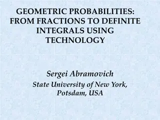
Example of a wireframe model lacking uniqueness The same edge and vertex list can describe different depending on how the faces are interpreted. objects, A wireframe model with an ambiguous orientation: the necker cube Which face is in front and which is in back?
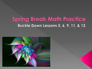
SURFACE MODELING In this approach, a component is represented by its surfaces which in turn are represented by their vertices and edges. For example, eight surfaces are put together to create a box, as shown in Fig. 2. Surface modeling has been very popular in aerospace product design and automotive design. Surface modeling has been particularly useful in the development of manufacturing codes for automobile panels and the complex doubly curved shapes of aerospace structures and dies and moulds. Surface Representation
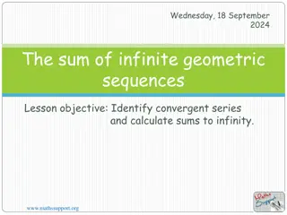
Surface modeling techniques are available for interactive modeling and editing of curved surface geometry. Surfaces can be created through an assembly of polygonal meshes or using advanced curve and surface modeling techniques like B-splines or NURBS (Non-Uniform Rational B- splines). Standard primitives used in a typical surface modeling software are shown in Fig. 3. Tabulated surfaces, ruled surfaces and edge surfaces and revolved are simple ways in which curved geometry could be created and edited. Typical Approaches in Surface Modeling
Examples commonly engineering design. of surfaces used in
Surfaces can be created using a number of different techniques. The technique used is determined both by the shape to be created and by the tools available in the surface modeler. Among the most popular methods for creating surfaces are sweeping, revolving, lofting and creating patches with curve boundaries or sets of points (point clouds). Sweeping is a modeling technique that allows you to define surfaces by moving a directrix along a generatrix The directrix is typically a 2-D curve, while the generatrix can be a line, planar curve, or 3-D curve. Figure 4 shows an oblique cylinder being created by moving a circle directrix along a straight line generatrix. Figure 4 also shows increasingly complex directrix curves being swept out with straight-line generatrixes to created ruled surfaces. Swept surfaces Generating swept surfaces by sweeping generator entities along director entities.
Using curved generatrixes allows for even more complex surface generation. An alternative to defining a generatrix directly is to revolve the directrix about an axis. Notice that a closed-curve directrix creates a tubelike, hollow surface model. A directrix can be rotated about an axis between 1 and 360 degrees.
Using a series of directrix curves to define multiple intermediate points along the generatrix path can create more complex surfaces. This technique, lofting, allows you to defi ne critical changes in the directrix shape over the surface. Lofting to define a surface Lofting uses two or more directrix curves to define a surface.
In addition to straight lines and circular curves, freeform curves such as B-splines and Bezier curves can be used to generate all or part of the curve. Freeform curves usually provide controls that allow you to both define the curve prior to surface generation and edit the resulting curve by redefining the original curves used to generate the surface. Freeform curves are regularly used to create surface patches from boundary curves. shows a surface patch made from four Bezier curves. To form a surface, the boundary curves should form a closed path. Just as with creating polygons, there need to be at least three boundary curves, but the surface can contain more than four. The upper limit is typically a practical matter of managing the surface. A Bezier bicubic surface patch The patch consists of four connected Bezier curves and 12 control points.
NURBS stands for Non-Uniform Rational B-Splines. Rational B-splines can define a wide variety of curves including linear, circular, and conic curves. This means that NURBS can define the complete set of curves used in a surface model and rapidly deform, changing curve type on the fly as needed. A bicycle frame defined with complex surface patches.
Solid models It includes Volumetric information, that is, what is on the inside of the 3-D model, as well as information about the surface of an object. In this case, the surface of the model represents the boundary between the inside and outside of the object. A complete solid is one which enables a point in space to be classified relative to the object, if it is inside, outside, or on the object A valid solid is the one that does not have dangling edges or faces An unambiguous solid has one and only one interpretation Solid modelling achieves completeness, validity, and unambiguity of geometric models
Geometry and Topology Geometry is the actual dimensions that define the entities of the object Topology is the connectivity and associativity of the object entities
Solid Entities All primitives can be created using base approach, why most of the CAD software don t provide built-in primitives feature that s
Modeling with primitives uses only a limited set of geometric primitives; therefore, only certain topologies can be created. This is called primitive instancing. A camera described with geometric primitives Additive modeling with geometric primitives allows a variety of objects to be represented.
The three Boolean operations: union, difference, and intersection The three operations, using the same primitives in the same locations, create very different objects.
The operands operation Unlike the union operation, the difference operation is sensitive to the ordering of operations. effects of ordering a difference of in
Boolean primitives Only the union operation is effective when primitives are adjoining but not overlapping. operations on adjoining
Properties of Solids Rigidity This implies that the shape of a solid model is invariant and does not depend on the model s location or its orientation in space Homogenous three-dimensionality Solid boundaries must be in contact with the interior. No isolated or dangling boundaries should be permitted Finiteness and finite describability Finiteness means that the size of the solid is not infinite, while finite describability ensures that a limited amount of information can describe the solid
Properties of Solids Closure under rigid motion and regularized Boolean operations The property ensures that manuplating solids by moving them in space or changing them via boolean operations must produce other valid solids Boundary determinism The boundary of the solid must contain the solid and hence must determine distinctivily
Solid Representation Schemes 1. Half Spaces 2. B-rep 3. CSG 4. Sweeps
Half-spaces By combining half-spaces, using set operations in a block fashion, various solids can be constructed. Each geometric entity divides the representation space in two infinite halves: Filled with material Empty
Half-spaces = ( , , : ) z 0 H x y z For planner surface For Cylindrical half-space = + 2 2 2 ( , , : ) z H x y x y R Spherical half-space ( ) = + + 2 2 2 2 , , : H x y z x y z R
Half-spaces Is only useful for research purpose Unbounded edges/faces cause system crash. Modeling is cumbersome Few software use half-space approach
Boundary Representation (B-rep) A B-rep model of an object consists of edges, faces, vertices, loops and handles
B-rep Face :closed, orientable and bounded by edges Edge :bounded by two vertices Vertex : a point in E Loop: hole in a face Handle: through hole in a solid
Euler Equations To validate the B-rep model, Euler equation is used which is given below; F E + V L = 2(B-G) Where F = faces E = Edges V = Vertices L = Loops B = Bodies G = genus (hollow space inside the model. i.e. a through hole)
Euler Equations Exp 9.7: Check the validity of 3D models shown:
CSG A physical model can be divided into a set of primitives that can be combined in a certain order using Boolean operations to form object. The data of the solid model is stored in its database in a tree called CSG Tree.
CSG Exp 9.9: Sketch the CSG tree for the solid S2 as shown
CSG Tree A designer can use the tree in various ways Trace the creation step Edit a feature or a primitive Prune the tree; moving an entire tree branch to a new location
Sweeps Sketching a cross-section and sweeping it Useful in creating a 2 D objects Both extrusion and revolution is possible Three type: Linear - the sweeping path is linear (for extrusion) or circular (for axisymmetric solid) vector Nonlinear the path is a curve described by a higher order (quadratic, cubic or higher) equation Hybrid combines linear and nonlinear sweeps


")


")