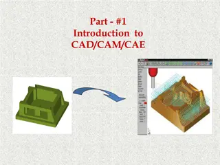
Effective CAD Design Strategies for Complex Assemblies
Dive into CAD design with a focus on creating assembly templates, standardization, and utilizing loft surfaces for efficient layout. Enhance your understanding of design principles for aerospace applications.

Download Presentation

Please find below an Image/Link to download the presentation.
The content on the website is provided AS IS for your information and personal use only. It may not be sold, licensed, or shared on other websites without obtaining consent from the author. Download presentation by click this link. If you encounter any issues during the download, it is possible that the publisher has removed the file from their server.
E N D
Presentation Transcript
CAD Design Part 1 AE460 Greg Marien Lecturer
Background/Purpose CAD is the tool of choice for modern design activity, providing: Accuracy of the design Ease of collaboration in the design and manufacturing of a product Ease of changes in the design This activity assumes You have had a course in SolidWorks and a working knowledge of the tool You will take pity on me since I only know Pro/E, CATIA, and NX Purpose: Set you up with a working knowledge of the rules to designing complex assembly Assist to get you started laying out your configuration Standardization is key to maximizing the efficiency of using CAD tools.
Standardization Create a Part Template and Assembly Template in the proper coordinate system orientation Use the Aircraft Coordinate System (ACS) method for design Use ACS for every part to ensure proper coordinate system Create the Loft Surfaces of the aircraft and lock it down from any changes ASAP Loft surfaces are also known as Outer Mold Line (OML) Use Loft Surfaces to create Layouts of: Primary Structure (load path) Control Surfaces Subsystems Landing Gear, Cockpit, Passenger compartment, Fuel Volumes/Tanks, LRUs, Payloads, etc. Make models as parametric as possible (I will show you how) The Layout is then used in design discussions for: Configuration Design during conceptual and preliminary design phases Design fesibility - Does it address all the requirements? Weight and Mass Balance Analysis Lift, Drag, Performance Analysis Cost Analysis Use General Arrangement and Inboard Profile drawings to foster real- time design discussions in your teams Trade Studies Comparisions of existing or competing aircraft
Part/Assembly Template for SolidWorks Requried Default Use STARTPART.SLDPRT and STARTASSY.SLDASM downloaded from class website Open the file in SW and do a SAVE AS, then Save as type .prtdot and .asmdot for part and assemblies, respectively. This allows you to have the template available when doing file->new. Why do this? Note the Default Global Coordinate System has Z axis on the horizontal plane. Also notice standard names for the planes: Front, Top and Right. This is not an aircraft design convention, therefore use the template I provide. 4
Example 5
Creating a STARTPART template 1. 2. 3. Create a new part In the isometric view, note the Z axis is in the horizontal plane (TOP Plane) Press the spacebar, bringing up the Orientationwindow then Pin Orientation pallet, just for ease of use. Click on FRONT view, making it normal and pointing to you. In the Orientation window click on Update Standard Views In the Orientation window click on the Top View You will receive a warning about the change, click Yes Click on Iso-view, which now shows the correct orientation Rename plane names to Water Line, Frame/Fuselage Station and Butt Line zeros as follows: 1. Front Plane to WL0 2. Top Plane to FS0 3. Right Plane to BL0 10. Add a Coordinate System (CS) to the part and rename the CS to ACS (May need to Rebuild to have the name show up properly) 11. Save part as a Part Template: call it STARTPART 12. Use the STARTPART for all your parts that are to be in one location only, i.e. loft, primary structural parts and control surface parts. Payloads, LRUs, etc, may be modeled at 0, 0, 0 and assembled into ACS. 4. 5. 6. 7. 8. 9. STARTASSY was also created in this way 7