DIFFERENTIAL AMPLIFIER CIRCUIT
DIFFERENTIAL AMPLIFIER CIRCUIT
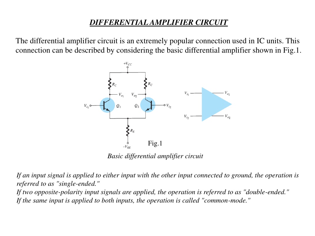
The differential amplifier circuit is an extremely popular connection used in IC units. This
connection can be described by considering the basic differential amplifier shown in Fig.1.
Fig.1
Basic differential amplifier circuit
If an input signal is applied to either input with the other input connected to ground, the operation is
referred to as "single-ended."
If two opposite-polarity input signals are applied, the operation is referred to as "double-ended."
If the same input is applied to both inputs, the operation is called "common-mode."
DC Bias
Let's first consider the dc bias operation of the circuit of Fig.1. With ac inputs obtained
from voltage sources, the dc voltage at each input is essentially connected to 0 V, as
shown in Fig. 2. With each base voltage at 0 V, the common-emitter dc bias voltage is
Fig. 2
DC bias of dijferential amplifier circuit.
EXAMPLE (1).
Calculate the dc voltages and currents in the circuit of Fig. 3.
Fig. 3
Solution
The collector current is then
resulting in a collector voltage of
The common-emitter voltage is thus -0.7 V, whereas the collector bias
voltage is near 4.1V for both outputs.
AC Operation of Circuit
An ac connection of a differential amplifier is shown in Fig. 4. Separate input signals
are applied as
V
i1
and
V
i2
, with separate outputs resulting as
V
o1
and
V
o2
. To carry out
ac analysis, we redraw the circuit in Fig. 5. Each transistor is replaced by its ac
equivalent.
Fig. 4
AC connection of differential amplifier.
Fig. 5
AC equivalent of differential amplifier circuit
Single-Ended AC Voltage Gain
:-
To calculate the single-ended ac voltage gain,
Vo/V
i
,
apply signal to one input with the other connected to ground, as shown in Fig. 6.
Fig. 6
Fig. 7
AC equivalent of circuit in Fig. 6.
The ac equivalent of this connection is drawn in Fig. 7. The ac base current can be calculated using the
base 1 input Kirchhoff voltage loop (KVL) equation. If one assumes that the two transistors are well
matched, then
and the output voltage magnitude at either collector is
Fig. 8
Partial circuit for calculating I
b
.
for which the single-ended voltage gain magnitude at either collector is
EXAMPLE (2):-
Calculate the single-ended output voltage
V
o1
for the circuit of Fig. 9
Fig. 9
Solution:
The dc bias calculations provide
The value of r
e
is then
providing an output ac voltage of magnitude
Double-Ended AC Voltage Gain
:-
A similar analysis can be used to show that for the condition of signals applied to both
inputs, the differential voltage gain magnitude is
Common-Mode Operation of Circuit
:-
Whereas a differential amplifier provides large amplification of the difference signal
applied to both inputs, it should also provide as small an amplification of the signal
common to both inputs. An ac connection showing common input to both transistors is
shown in Fig. 10. The ac equivalent circuit is drawn in Fig. 11, from which we can write.
which can be rewritten as
The output voltage magnitude is then
providing a voltage gain magnitude of
Fig. 10
Common-mode connection.
Fig. 11
AC circuit in common-mode connection.
The differential amplifier circuit is commonly used in IC units. Learn about single-ended, double-ended, and common-mode operations, along with DC bias and AC analysis. Calculate DC voltages and currents, understand AC voltage gain, and solve examples to comprehend the functioning of a differential amplifier circuit.

Download Presentation

Please find below an Image/Link to download the presentation.
The content on the website is provided AS IS for your information and personal use only. It may not be sold, licensed, or shared on other websites without obtaining consent from the author.If you encounter any issues during the download, it is possible that the publisher has removed the file from their server.
You are allowed to download the files provided on this website for personal or commercial use, subject to the condition that they are used lawfully. All files are the property of their respective owners.
The content on the website is provided AS IS for your information and personal use only. It may not be sold, licensed, or shared on other websites without obtaining consent from the author.
E N D
Presentation Transcript
DIFFERENTIAL AMPLIFIER CIRCUIT The differential amplifier circuit is an extremely popular connection used in IC units. This connection can be described by considering the basic differential amplifier shown in Fig.1. Fig.1 Basic differential amplifier circuit If an input signal is applied to either input with the other input connected to ground, the operation is referred to as "single-ended." If two opposite-polarity input signals are applied, the operation is referred to as "double-ended." If the same input is applied to both inputs, the operation is called "common-mode."
DC Bias Let's first consider the dc bias operation of the circuit of Fig.1. With ac inputs obtained from voltage sources, the dc voltage at each input is essentially connected to 0 V, as shown in Fig. 2. With each base voltage at 0 V, the common-emitter dc bias voltage is Fig. 2 DC bias of dijferential amplifier circuit.
EXAMPLE (1). Calculate the dc voltages and currents in the circuit of Fig. 3. Solution The collector current is then Fig. 3 resulting in a collector voltage of The common-emitter voltage is thus -0.7 V, whereas the collector bias voltage is near 4.1V for both outputs.
AC Operation of Circuit An ac connection of a differential amplifier is shown in Fig. 4. Separate input signals are applied as Vi1 and Vi2, with separate outputs resulting as Vo1 and Vo2. To carry out ac analysis, we redraw the circuit in Fig. 5. Each transistor is replaced by its ac equivalent. Fig. 4 AC connection of differential amplifier. Fig. 5 AC equivalent of differential amplifier circuit
Single-Ended AC Voltage Gain:- To calculate the single-ended ac voltage gain, Vo/Vi, apply signal to one input with the other connected to ground, as shown in Fig. 6. Fig. 6 Fig. 7 AC equivalent of circuit in Fig. 6.
The ac equivalent of this connection is drawn in Fig. 7. The ac base current can be calculated using the base 1 input Kirchhoff voltage loop (KVL) equation. If one assumes that the two transistors are well matched, then Fig. 8 Partial circuit for calculating Ib. and the output voltage magnitude at either collector is for which the single-ended voltage gain magnitude at either collector is
EXAMPLE (2):- Calculate the single-ended output voltage Vo1 for the circuit of Fig. 9 Solution: The dc bias calculations provide The value of re is then Fig. 9 providing an output ac voltage of magnitude
Double-Ended AC Voltage Gain:- A similar analysis can be used to show that for the condition of signals applied to both inputs, the differential voltage gain magnitude is Common-Mode Operation of Circuit:- Whereas a differential amplifier provides large amplification of the difference signal applied to both inputs, it should also provide as small an amplification of the signal common to both inputs. An ac connection showing common input to both transistors is shown in Fig. 10. The ac equivalent circuit is drawn in Fig. 11, from which we can write. which can be rewritten as The output voltage magnitude is then
providing a voltage gain magnitude of Fig. 11 Fig. 10 AC circuit in common-mode connection. Common-mode connection.


. Calculate the dc voltages and currents in the")


:- Calculate the single-ended output voltage Vo1")