Practical Op-Amp Circuits: Inverting, Noninverting, and More
Explore practical op-amp circuits such as inverting amplifier, noninverting amplifier, unity follower, summing amplifier, and integrator. Learn how to calculate output voltages for various configurations and understand their applications with examples.

Download Presentation

Please find below an Image/Link to download the presentation.
The content on the website is provided AS IS for your information and personal use only. It may not be sold, licensed, or shared on other websites without obtaining consent from the author.If you encounter any issues during the download, it is possible that the publisher has removed the file from their server.
You are allowed to download the files provided on this website for personal or commercial use, subject to the condition that they are used lawfully. All files are the property of their respective owners.
The content on the website is provided AS IS for your information and personal use only. It may not be sold, licensed, or shared on other websites without obtaining consent from the author.
E N D
Presentation Transcript
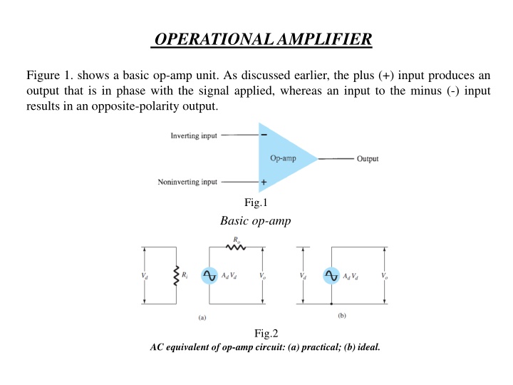
OPERATIONAL AMPLIFIER Figure 1. shows a basic op-amp unit. As discussed earlier, the plus (+) input produces an output that is in phase with the signal applied, whereas an input to the minus (-) input results in an opposite-polarity output. Fig.1 Basic op-amp Fig.2 AC equivalent of op-amp circuit: (a) practical; (b) ideal.
PRACTICAL OP-AMP CIRCUITS Inverting Amplifier:- The most widely used constant-gain amplifier circuit is the inverting amplifier, as shown in Fig.3. Example (1). Assuming that the operational amplifier in Figure (3) is ideal, R1 = 100k , Rf= 500k . Find the output voltage when vin is 2v? Solution:
The Noninverting Amplifier:- Figure (4) shows another useful application of an operational amplifier, called the noninvertins configuration. EXAMPLE (2) Calculate the output voltage of a noninverting amplifier for values of Vi = 2v , Rf = 500 k , and R1 = 100 k .
Unity Follower ( Buffer):- The unity-follower circuit, as shown in Fig. 5, provides a gain of unity (1) with no polarity or phase reversal. Fig.5 Fig(5) Unity follower Summing Amplifier:- Fig.6 Summing amplifier
EXAMPLE (3) Calculate the output voltage of an op-amp summing amplifier for the following sets of voltages and resistors. Use Rf= 1M . V1= 1v, V2= 2v,V3= 3v , R1= 500k , R2= 1M , R3= 1M ? Solution:
Integrator :- Fig.7 From our rules and previous experience we know that v- =0 and from kirchhoff s current law we get
More than one input may be applied to an integrator, as shown in Fig. 8, with the resulting operation given by Fig.8 EXAMPLE (4):- Find the output voltage of the op-amp integrator if Vi = Vm sin wt ? Solution:
EXAMPLE (5):- If R = 10k and C = 0.1F, Viis square wave of 5v amplitude of 1kHz frequency. Draw the output waveform? Solution:
Differentiator:- Fig.9 It can be shown that the output of this differentiator, since the current into the interval is 0, and we have from the kirchhoff s current law is
EXAMPLE (6):- If R = 10k and C = 0.1F, Viis sawtooth wave of 10v amplitude of 1kHz frequency. Find and draw the output waveform? Solution
Difference Amplifier:- Fig.10 (a) Op-amp difference amplifier, (b) difference amplifier with v12 = 0 and (c) difference amplifier with v11 = 0
A property of the ideal difference amplifier is that the output voltage is zero when v11 = v12 .This condition is met if
Amplifier with a T-Network:- Fig.11 Inverting op-amp with T-network
EXAMPLE (7):- Find the output voltage for the summing amplifier as shown in figure (12). Solution:- Fig.12 EXAMPLE (8):- determine ( Vo ) as a function of V11 and V12for the ideal noninverting op-amp circuit in figure (13)? Fig.13
H.W For the circuit shown in Figure (14). (a) Derive the expression for the closed-loop voltage gain Av = Vo / Vi Assume an ideal op-amp. (b) Let R4 = 50k and R3 = 25 k . Determine R1 and R2 such that Av = 6, assuming the maximum resistor value is limited to 200 k . Fig.14 EXAMPLE (9) :- (a) Consider the ideal op-amp circuit shown in Figure (15). Determine the voltage gains Av1 =Vo1 / V1and Av2 =Vo2 / V1. (b) ForR2= 60k ,R1= 20k , andR =50k , determine Vo1andVo2 for V1 = -0.5V. Solution :-(a) (b) Fig.15
H.W 1) Consider the circuit in Figure (16). (a) Derive the expression for the output voltage Vo in terms of VI1 and VI2. (b) Determine Vo for VI1 = 5 mv and VI2 = 0.2v. Fig.16 2) Determine the gain for the op-amp circuit shown in Figure (17). Fig.17
3) a) Drive the closed loop gain of the op-amp circuit illustrated in figure (18). b) What is the gain when R1=R2=10k ,R3=5k , and R4=15k ? Fig.18


:-")
 Calculate the output voltage of an")


:- If R = 10kΩ and C = 0.1µF, Viis square wave")

:- If R = 10kΩ and C = 0.1µF, Viis sawtooth")


:- Find the output voltage for the summing")


 a) Drive the closed loop gain of the op-amp circuit")