Design of Asynchronous State Machine Steps and Example Circuit
Steps for designing an asynchronous state machine including primitive state diagram, flow table reduction, merging, adjacency sets, and flow table assignments. An example circuit design with S-R flip-flops for a specific sequential logic requirement is demonstrated.
Download Presentation

Please find below an Image/Link to download the presentation.
The content on the website is provided AS IS for your information and personal use only. It may not be sold, licensed, or shared on other websites without obtaining consent from the author.If you encounter any issues during the download, it is possible that the publisher has removed the file from their server.
You are allowed to download the files provided on this website for personal or commercial use, subject to the condition that they are used lawfully. All files are the property of their respective owners.
The content on the website is provided AS IS for your information and personal use only. It may not be sold, licensed, or shared on other websites without obtaining consent from the author.
E N D
Presentation Transcript
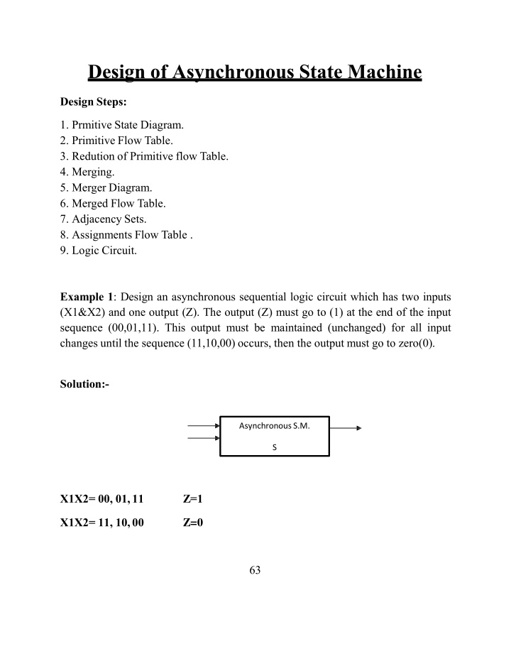
Design of Asynchronous State Machine Design Steps: 1. Prmitive State Diagram. 2. Primitive Flow Table. 3. Redution of Primitive flow Table. 4. Merging. 5. Merger Diagram. 6. Merged Flow Table. 7. Adjacency Sets. 8. Assignments Flow Table . 9. Logic Circuit. Example 1: Design an asynchronous sequential logic circuit which has two inputs (X1&X2) and one output (Z). The output (Z) must go to (1) at the end of the input sequence (00,01,11). This output must be maintained (unchanged) for all input changes until the sequence (11,10,00) occurs, then the output must go to zero(0). Solution:- AsynchronousS.M. S X1X2= 00, 01,11 Z=1 Z=0 X1X2= 11, 10,00 63
1. Prmitive StateDiagram. 2. Primitive flow table. 64
3- Reduction of Primitive flow table using implication chart. X 2 X X 3 4 X X X X X X X 5 6 X X X X X X X X X X X 7 X X X X X X X 8 X 3,7 X X X X X X 9 10 X X X 1,8 X X X X X 1 2 3 4 5 6 7 8 9 N0 Reduction 4- Merging. m=(1,2) (1,5) (2,4) (3,4) (3,6) (5,7) (5,9) (6,8) (6,10) (7,9) (8,10). and 5. The Merger Diagram. Create the Merger Diagram, M=(1,2) (3,4) (5,7,9) (6,8,10) 65
6. Merged FlowTable. 00 1 1 01 2 6 11 3 3 10 5 4 Z o/p 0 1 A B C D 1 8 9 6 7 3 5 10 0 1 7. Adjacency Sets. X1X2=00 X1X2=01 X1X2=11 X1X2=10 (a,b,c); (b,d); (a,b,d); (a,c) Y1 1 Y2 0 A B 0 C D 1 (Row Transition Map) Note: The stable state take the code of the same row and the unstable state take the code of it's row where they are stable. 8. Assignments Flow Table . 66 Inputs X1X2 01 y1y2 y1y2 Z 00 11 10 o/p y1y2 y1y2 y1y2
a b c d 0 0 1 0 0 1 1 1 0 0 0 0 0 0 1 1 0 0 1 1 0 1 1 1 1 0 1 0 0 1 1 0 0 1 1 0 0 1 1 1 0 1 0 1 "Assigned FlowTable" Circuit Relaization:- Design the circuit using the S-R flip-flops. X1X2 01 X1X2 y1y2 01 11 10 11 10 y1y2 X X 0 X 0 0 1 0 00 00 X X X X 0 0 0 0 01 01 0 0 0 0 X X X X 11 11 1 0 0 0 0 X X X 10 10 Sy1=X1X2? ? Ry1=? 1? 2? 2 67 X1X2 X1X2 01 01 11 10 y1y2 11 10 y1y2 0 0 0 1 00 00 0 X X X 01 01 11 11 10 10
X X 0 0 X X X 0 0 1 0 0 1 0 0 0 0 0 1 0 X 0 X 0 Ry2=? 1? 2? 1 + X1X2y1 Sy2=? 1X2y1 + X1? 2? 1 X1X2 y1y2 01 11 10 0 0 X X 00 X 0 0 0 01 1 1 X 1 11 X X 1 1 10 Z=y1 68
