8-bit Timer/Counter2 with PWM and Asynchronous Operation
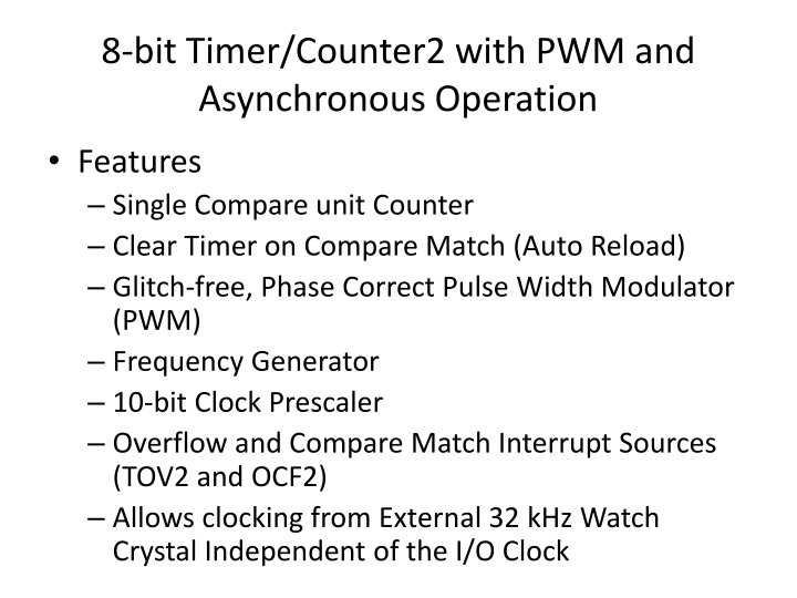
The 8-bit Timer/Counter2 with PWM and Asynchronous Operation features single compare unit, glitch-free operation, phase-correct PWM, frequency generator, clock prescaler, interrupt sources, and external clocking options. It includes registers for control, counter, output compare, asynchronous status, interrupt mask, and special functions. Various bits in the control register determine output compare, waveform generation mode, compare match output mode, and clock selection. Additionally, the asynchronous status register manages timer/counter updates when operating asynchronously.
Download Presentation

Please find below an Image/Link to download the presentation.
The content on the website is provided AS IS for your information and personal use only. It may not be sold, licensed, or shared on other websites without obtaining consent from the author.If you encounter any issues during the download, it is possible that the publisher has removed the file from their server.
You are allowed to download the files provided on this website for personal or commercial use, subject to the condition that they are used lawfully. All files are the property of their respective owners.
The content on the website is provided AS IS for your information and personal use only. It may not be sold, licensed, or shared on other websites without obtaining consent from the author.
E N D
Presentation Transcript
8-bit Timer/Counter2 with PWM and Asynchronous Operation Features Single Compare unit Counter Clear Timer on Compare Match (Auto Reload) Glitch-free, Phase Correct Pulse Width Modulator (PWM) Frequency Generator 10-bit Clock Prescaler Overflow and Compare Match Interrupt Sources (TOV2 and OCF2) Allows clocking from External 32 kHz Watch Crystal Independent of the I/O Clock
Registers TCCR2 Timer/Counter Control Register TCNT2 Timer/Counter Register OCR2 Output Compare Register ASSR Asynchronous Status Register TIMSK Timer/Counter Interrupt Mask Register TIFR Timer/Counter Interrupt Flag Register SFIOR Special Function IO Register
TCCR2 Timer/Counter Control Register Bit 7 FOC2: Force Output Compare Bit 3, 6 WGM2[1:0]: Waveform Generation Mode Bit 5:4 COM21:0: Compare Match Output Mode Bit 2:0 CS22:0: Clock Select
ASSR Asynchronous Status Register Bit 3 AS2: Asynchronous Timer/Counter2 Bit 2 TCN2UB: Timer/Counter2 Update Busy Bit 1 OCR2UB: Output Compare Register2 Update Busy Bit 0 TCR2UB: Timer/Counter Control Register2 Update Busy
Bit 3 AS2: Asynchronous Timer/Counter2 When AS2 is written to zero, Timer/Counter 2 is clocked from the I/O clock, clkI/O. When AS2 is written to one, Timer/Counter2 is clocked from a Crystal Oscillator connected to the Timer Oscillator 1 (TOSC1) pin. When the value of AS2 is changed, the contents of TCNT2, OCR2, and TCCR2 might be corrupted.
Bit 2 TCN2UB: Timer/Counter2 Update Busy When Timer/Counter2 operates asynchronously and TCNT2 is written, this bit becomes set. When TCNT2 has been updated from the temporary storage register, this bit is cleared by hardware. A logical zero in this bit indicates that TCNT2 is ready to be updated with a new value.
Bit 1 OCR2UB: Output Compare Register2 Update Busy When Timer/Counter2 operates asynchronously and OCR2 is written, this bit becomes set. When OCR2 has been updated from the temporary storage register, this bit is cleared by hardware. A logical zero in this bit indicates that OCR2 is ready to be updated with a new value.
Bit 0 TCR2UB: Timer/Counter Control Register2 Update Busy When Timer/Counter2 operates asynchronously and TCCR2 is written, this bit becomes set. When TCCR2 has been updated from the temporary storage register, this bit is cleared by hardware. A logical zero in this bit indicates that TCCR2 is ready to be updated with a new value. If a write is performed to any of the three Timer/Counter2 Registers while its update busy flag is set, the updated value might get corrupted and cause an unintentional interrupt to occur. The mechanisms for reading TCNT2, OCR2, and TCCR2 are different. When reading TCNT2, the actual timer value is read. When reading OCR2 or TCCR2, the value in the temporary storage register is read.
TIMSK Timer/Counter Interrupt Mask Register Bit 7 OCIE2: Timer/Counter2 Output Compare Match Interrupt Enable Bit 6 TOIE2: Timer/Counter2 Overflow Interrupt Enable
TIFR Timer/Counter Interrupt Flag Register Bit 7 OCF2: Output Compare Flag 2 Bit 6 TOV2: Timer/Counter2 Overflow Flag
Bit 7 OCF2: Output Compare Flag 2 The OCF2 bit is set (one) when a compare match occurs between the Timer/Counter2 and the data in OCR2 Output Compare Register2. OCF2 is cleared by hardware when executing the corresponding interrupt handling vector. Alternatively, OCF2 is cleared by writing a logic one to the flag. When the I-bit in SREG, OCIE2 (Timer/Counter2 Compare match Interrupt Enable), and OCF2 are set (one), the Timer/Counter2 Compare match Interrupt is executed
Bit 6 TOV2: Timer/Counter2 Overflow Flag The TOV2 bit is set (one) when an overflow occurs in Timer/Counter2. TOV2 is cleared by hardware when executing the corresponding interrupt handling vector. Alternatively, TOV2 is cleared by writing a logic one to the flag. When the SREG I-bit, TOIE2 (Timer/Counter2 Overflow Interrupt Enable), and TOV2 are set (one), the Timer/Counter2 Overflow interrupt is executed. In PWM mode, this bit is set when Timer/Counter2 changes counting direction at $00.
SFIOR Special Function IO Register Bit 1 PSR2: Prescaler Reset Timer/Counter2 When this bit is written to one, the Timer/Counter2 prescaler will be reset. The bit will be cleared by hardware after the operation is performed. Writing a zero to this bit will have no effect. This bit will always be read as zero if Timer/Counter2 is clocked by the internal CPU clock. If this bit is written when Timer/Counter2 is operating in asynchronous mode, the bit will remain one until the prescaler has been reset.
