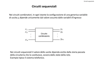
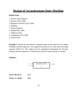
D Latches and Flip-Flops in Digital Systems
Digital systems rely on storage elements like D latches and flip-flops to store key information from the past. These structures can hold values of 1 or 0 based on certain control signals, ensuring deterministic behavior. Clock signals are essential for regulating when these storage elements can update, providing a pre-determined rate of change. By utilizing D latches, flip-flops, and clock signals, designers can create circuits with controlled and predictable behavior in storing data.

Download Presentation

Please find below an Image/Link to download the presentation.
The content on the website is provided AS IS for your information and personal use only. It may not be sold, licensed, or shared on other websites without obtaining consent from the author.If you encounter any issues during the download, it is possible that the publisher has removed the file from their server.
You are allowed to download the files provided on this website for personal or commercial use, subject to the condition that they are used lawfully. All files are the property of their respective owners.
The content on the website is provided AS IS for your information and personal use only. It may not be sold, licensed, or shared on other websites without obtaining consent from the author.
E N D
Presentation Transcript
ECE 352 Digital System Fundamentals D Latches and Flip-Flops D Latches and Flip-Flops 1 1 1
Storage Elements Many interesting types of circuits require keeping track of what happened in the past D Latches and Flip-Flops Need to store some of this past information Generally not storing everything that happened, just some key information Example: Vending machine Needs to track how much money was inserted Doesn t need to track which coins/bills were used How can we store this data? 2 2 2
What Does This Do? Once we can get a value into this structure, it stays there as long as the circuit has power Q Q D Latches and Flip-Flops Can hold a 1 Can hold a 0 Q Q Q Q 1 0 0 1 How do we get a value into this structure in the first place? 3 3 3
D Latch with Control Want to control what goes into the storage element and when it happens The bottom inverter is weak, and the tristate can overpower it without damage This latch is level-sensitive: the value held in the latch can change whenever signal C is 1 D Latches and Flip-Flops Symbol Q D Q D Q C C 4 4 4
Level-Sensitivity Problem Consider a counter built with latches: 0 0 1 D Latches and Flip-Flops D Q D Q D Q S2 A2 S1 A1 S0 A0 C C C C Stored value could update many times while C=1 The number of times it updates is unpredictable! Update rate also depends on ambient temperature We want to update once per pulse on signal C We want deterministic behavior! 5 5 5
Clock Signal Need ability to make circuits where the storage elements only change at a pre-determined rate A clock is a special signal that oscillates between value of 1 and 0 at a specific frequency Controls how often the storage elements can update D Latches and Flip-Flops ( negative edge) ( positive edge) rising edge falling edge cycle time 6 6 6
D Flip-Flop Build a flip-flop (FF) by connecting two latches so the first latch s output is the second s input The output of the below flip-flop only changes on the negative edge of the control signal (the clock) D Latches and Flip-Flops Flip-Flop 1st Latch 2nd Latch Symbol Q D Q Y Y D D Q Y Y CLK CLK bubble means negative-edge! 7 7 7
Flip-Flop Waveform The waveform demonstrates how the two latches work together to act as an edge-triggered FF Colors on the waveform indicate which latch is enabled Y Q D Latches and Flip-Flops D D Q D Q FF output Q changes on negative clock edge CLK C C CLK The first latch is only enabled when the second cannot change. The second latch is only enabled when the first cannot change. D Y Q 8 8 8
Positive-Edge Triggering A positive-edge triggered flip-flop can be constructed by adding an inverter This changes which latch is enabled for the high vs. low phase of the clock D Latches and Flip-Flops Symbol D Q Q Y D Q Y CLK no bubble means positive-edge! 9 9 9
Flip-Flops and Timing Waveforms In reality, there is some delay after the active clock edge before the FF input is stored and appears at the FF output D Latches and Flip-Flops B A D Q D Q Y CLK CLK A B Y Y Y Y Y Y Y CLK A B B B B B B CLK A A A A A CLK CLK CLK CLK 10 10 10
Flip-Flops and Functional Waveforms The functional waveform does not show delay, but it still expresses causality The value of a FF s output just after the active clock edge is the value of its input just before that clock edge D Latches and Flip-Flops B A D Q D Q Y CLK B s changes do not show up at Y until the next clock edge! CLK A B Y 11 11 11
Flip-Flop Direct Inputs Sometimes we need a FF to hold a specific value immediately (before the next active clock edge) An asynchronous input affects the flip-flop immediately, without requiring an active clock edge A synchronous input has no effect unless the clock is at an active edge D Latches and Flip-Flops Symbol Commonly used to force a circuit s flip-flops into a known desired state on start-up Direct set (preset) forces flip-flop to 1 Direct reset (clear) forces flip-flop to 0 PRE D Q CLR 12 12 12
Flip-Flops Direct Inputs In Quartus The flip-flops available in Quartus have active- low preset (PRN) and clear (CLRN) inputs PRN = 0 forces the FF to immediately store a 1 CLRN = 0 forces the FF to immediately store a 0 You need to tie these inputs to 1 (VCC) to disable them if you are not using them! D Latches and Flip-Flops VCC PRN D D Q Q Do NOT leave them unconnected! CLK CLRN RST D flip-flop with reset and disabled preset 13 13 13
ECE 352 Digital System Fundamentals D Latches and Flip-Flops D Latches and Flip-Flops 14 14 14
Questions A. A latch is ____-sensitive. B. A flip-flop is ____-sensitive. C. The output of a negative-edge triggered flip-flop only changes when ____. D.The output of a positive-edge triggered flip-flop only changes when ____. E. When an asynchronous preset input is active, it forces the flip-flop to ____. F. When an asynchronous clear input is active, it forces the flip-flop to ____. D Latches and Flip-Flops 15 15 15