CLAS12 Trigger System Upgrade Plan May 6, 2020

CLAS12 Trigger System Upgrade Plan
May 6, 2020
S.Boyarinov, B.Raydo
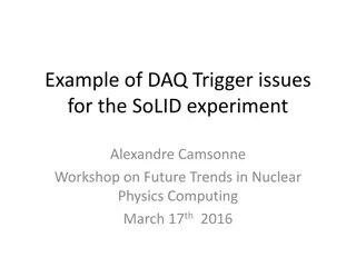
CLAS12 Trigger Upgrade Goals
•
With projected beam current increase, keep trigger efficiency close to 100% (make sure
we are not loosing MIP clusters in ECAL, etc)
•
Increase trigger purity to keep L1 trigger rate well below 100kHz – projected limitation
for DAQ
•
Add L3 for additional data rate reduction
2
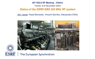
CLAS12 Existing Trigger System Hardware
3
CLAS12 Trigger Overview
•
Current CLAS12 Level 1 trigger is based on information coming from two types of front-end
boards: FADC250 (Flash ADC) and DCRB (Drift Chamber Readout Board)
•
FADC250s are used in HTCC, ECAL, PCAL, FTOF, CTOF, CND, FT_CAL and FT_HODO
•
DCRBs are used in Drift Chamber
•
L1 trigger consists of 3 stages and implemented using two types of specialized logic boards:
VTP (stage 1 and 3) and SSP (stage 2); L1 trigger is fixed latency system with the latency less
then 8us
•
Stage 1 receives initial hits from front-end boards and produces objects suitable for the
following trigger stages; those objects includes calorimeter clusters, drift chamber roads, and
hits from time-of-flight and Cherenkov counters
•
Stage 2 collects information from one CLAS12 sector and produces sector-based trigger
decision
•
Stage 3 collects information from all sectors and central detectors, and delivers final trigger
decision to Trigger Supervisor as 32 bit word every 4ns with pre-scaling for every bit
•
Every stage of the trigger system has flexible logic controlled by set of configuration
parameters, allowing to specify energy cuts, timing coincidences, geometrical matches (DC-
FTOF-PCALU, CTOF-CND, FT_CAL-FT_HODO so far), multiplicity and combinatorial logic
4
CLAS12 L1 Trigger Possible Upgrades
•
ECAL/PCAL trigger can to be improved in following ways: (1) in addition to electron
shower clustering, search for MIP-like clusters have to be added to improve muon class
triggers; (2) use individual strip real attenuation length instead of average one; (3) allow
individual strip timing delays and improve cluster timing reporting
•
DC trigger can be improved (needed in particular for Q**2 cuts) in following ways: (1)
segments selectivity and space resolution improvement; (2) roads space resolution
improvement; (3) drift time usage to improve two previous items feather
•
Additional geometry matching between detectors, for example DC vs PCAL clusters,
•
Allow multi-particle trigger in one sector
•
Improve trigger timing in every component and stage to straighten timing coincidence
5
See following slides for details on every item
ECAL/PCAL Trigger Upgrade
•
in addition to electron shower clustering, search for MIP-like clusters have to be added
to improve muon class triggers
–
it can be challenging, we have to conduct two cluster
searches, one with highest energy and another with MIP energy; will try and see if it
will fit into fpga; another solution can be to search for the MIP cluster only if DC track is
present, in that case cluster assembly can be done around track hit point,
independently of electron clustering search, however DC track info is not available at
stage 1 where EC cluster search is conducted
–
all that needs to be studied
•
use individual strip real attenuation length instead of average one
–
can be done, it
should improve cluster energy resolution and allows more precise energy cuts
•
allow individual strip timing delays and improve cluster timing reporting
–
can be done
•
completely new approach can use AI, have to be studied
6
Direction A: modify existing firmware to report up to 4 clusters with maximum energy
AND up to 4 clusters with MIP energy and appropriate number of strips;
if not successful, we’ll discuss another approach;
implement other improvements (individual strips attenuation, better timing etc)
Direction B: develop completely new firmware based on AI, see ‘Geometry
Matching Upgrade’ slide
Drift Chamber Trigger Upgrade
•
segments selectivity and space resolution improvement: for offline reconstruction
purposes, Mac suggested to modify DCRB to have multi-hit reporting in some form
(‘time-over-threshold’ etc), if implemented it may effect trigger segment search; in
general not much can be done on hit-based level to improve existing segment finder
•
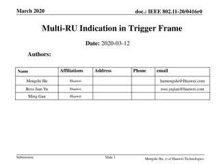
roads space resolution improvement: with new unit with bigger fpga (see picture
below) or/and road dictionary reorganization, single-cell dictionary can be used to
improve space resolution, however dictionary incompleteness may require to use
smearing (doing it now) and it will decrease resolution again; offline modeling is
strongly suggested to study possible road dictionary improvements
•
drift time usage to improve two previous items further: if timing information is used, it
can potentially improve segment search selectivity and precision, as for road finding;
again, all remarks from previous item is applicable here, and in addition it is unclear
how exactly to use hits timing
–
offline modeling is needed
•
Dictionary generation: data vs simulation, completeness
•
AI approach should be tested for segment finding, especially with timing usage, it may
be promising. Also for road finding to compare resource requirements vs dictionary
approach.
7
Plan: offline studies to measure possible improvements in segment
finding/road finding/timing usage/AI approach; goal is momentum and
space resolution; if improvements are possible, discuss implementation
Geometry Matching Upgrade
•
Additional geometry matching between detectors, for example DC vs PCAL clusters: it
can be implemented on stage 2 (no need on stage 3 since we do not have cross-sector
tracks); we may need to increase bandwidth from stage 1 to stage 2 to report required
information for geometry match
•
AI approach can be used for DC geometry matching with outer detectors
8
Direction A: work starts after ECAL and DC components redesign is decided
Direction B: resolve it as part of AI approach
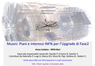
Multi-particle Logic Upgrade
•
Allow multi-particle trigger in one sector: it have to be considered in connection with
DC stage 1 and geometry matching upgrades; in general, it should be relatively easy to
count tracks matched for example with EC clusters and FTOF, but not practical to count
tracks alone since road dictionary produces a number of solutions for the same track
–
needs to be studied
9
Plan: work starts after ECAL and DC components redesign is decided
Trigger Timing Upgrade
•
Improve trigger timing in every component and stage to straighten timing coincidence
–
as simple as this, just go though full logic chain and see where we can define timing
more precisely
10
Plan: keep it in mind while working on every component redesign
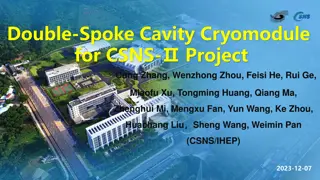
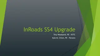
Hardware Upgrade
•
The only hardware change will be needed if modified DC road finder will need bigger
fpga, in that case we recommend to install new units (one per sector) between stage 1
and stage 2, with fiber connections to both; in that scheme existing DC Stage 1 can be
designated for DC segment finding only
–
see following slide
•
New units can replace Stage 2 completely
11
Plan: do it if needed
CLAS12 Trigger System Hardware Upgrade
12
New Road Finder
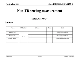
CLAS12 Level3 for Extra Data Rate Reduction
13
Level 3 can provide additional data rate
reduction, it is our strong recommendation to
offline data processing community to identify
packages which can be used in Level 3; DAQ
infrastructure is ready, any an assistance in
implementation will be provided
Level 3 is existing DAQ component,
running between Event Builder and
Event Recorder, currently dummy
Conclusion
•
Trigger rate below 100kHz for expected beam current increase is achievable
•
Existing fpga-based trigger system allows to implement most of needed features by
upgrading firmware
•
If needed, Stage 2 can be replaced with advanced fpga-based hardware
•
L3 trigger for additional data rate reduction is strongly desired
•
Project can be complete in 2-years scale, manpower have to be assigned to the project
for significant portion of that time period
14
CLAS12 Trigger System is undergoing an upgrade to enhance trigger efficiency, purity, and data rate reduction. The existing hardware and trigger overview provide insight into the current system's components and operation. The upgrade goals aim to maintain high trigger efficiency, reduce data rates, and improve trigger purity to meet projected beam current increase. The system consists of front-end boards, logic boards, and three trigger stages. Each stage processes hits and information from various detectors to make trigger decisions. Flexible logic parameters allow for customization of energy cuts, timing coincidences, and more.

Download Presentation

Please find below an Image/Link to download the presentation.
The content on the website is provided AS IS for your information and personal use only. It may not be sold, licensed, or shared on other websites without obtaining consent from the author.If you encounter any issues during the download, it is possible that the publisher has removed the file from their server.
You are allowed to download the files provided on this website for personal or commercial use, subject to the condition that they are used lawfully. All files are the property of their respective owners.
The content on the website is provided AS IS for your information and personal use only. It may not be sold, licensed, or shared on other websites without obtaining consent from the author.
E N D
Presentation Transcript
CLAS12 Trigger System Upgrade Plan May 6, 2020 S.Boyarinov, B.Raydo
CLAS12 Trigger Upgrade Goals With projected beam current increase, keep trigger efficiency close to 100% (make sure we are not loosing MIP clusters in ECAL, etc) Increase trigger purity to keep L1 trigger rate well below 100kHz projected limitation for DAQ Add L3 for additional data rate reduction 2
CLAS12 Existing Trigger System Hardware S6 S5 S4 S3 S2 S1 VTP (VXS Trigger Processor) INPUTS: ECAL and LTCC FADCs OUTPUT: Clusters VTP (VXS Trigger Processor) INPUTS: PCAL FADCs OUTPUT: Clusters VTP (VXS Trigger Processor) INPUTS: FTOF FADCs OUTPUT: Hits VTP (VXS Trigger Proc) INPUTS: Central TOF OUTPUTS: Hits SSP SSP SSP SSP SSP SSP SSP (Sub System Processor), Sector 1 Sector based trigger decision CEN S6 S5 S4 S3 S2 VTP (VXS Trigger Proc) TS INPUTS: HTCC OUTPUTS: Hits VTP (as Global Trig Processor) 32 VTP (VXS Trigger Proc) INPUTS: FT/HODO OUTPUTS: Clusters Global Trigger decision 16 VTP (VXS Trigger Proc) INPUTS: CND Pulser, Helicity etc OUTPUTS: Hits S6 S5 S4 S3 S2 S1 VTP (VXS Trigger Proc) INPUTS: Drift Chamber Region 1 OUTPUT: list of track segments VTP (VXS Trigger Proc) INPUTS: Drift Chamber Region 2 OUTPUT: list of track segments VTP (VXS Trigger Proc) INPUTS: Drift Chamber Region 3 OUTPUT: list of track segments 3
CLAS12 Trigger Overview Current CLAS12 Level 1 trigger is based on information coming from two types of front-end boards: FADC250 (Flash ADC) and DCRB (Drift Chamber Readout Board) FADC250s are used in HTCC, ECAL, PCAL, FTOF, CTOF, CND, FT_CAL and FT_HODO DCRBs are used in Drift Chamber L1 trigger consists of 3 stages and implemented using two types of specialized logic boards: VTP (stage 1 and 3) and SSP (stage 2); L1 trigger is fixed latency system with the latency less then 8us Stage 1 receives initial hits from front-end boards and produces objects suitable for the following trigger stages; those objects includes calorimeter clusters, drift chamber roads, and hits from time-of-flight and Cherenkov counters Stage 2 collects information from one CLAS12 sector and produces sector-based trigger decision Stage 3 collects information from all sectors and central detectors, and delivers final trigger decision to Trigger Supervisor as 32 bit word every 4ns with pre-scaling for every bit Every stage of the trigger system has flexible logic controlled by set of configuration parameters, allowing to specify energy cuts, timing coincidences, geometrical matches (DC- FTOF-PCALU, CTOF-CND, FT_CAL-FT_HODO so far), multiplicity and combinatorial logic 4
CLAS12 L1 Trigger Possible Upgrades ECAL/PCAL trigger can to be improved in following ways: (1) in addition to electron shower clustering, search for MIP-like clusters have to be added to improve muon class triggers; (2) use individual strip real attenuation length instead of average one; (3) allow individual strip timing delays and improve cluster timing reporting DC trigger can be improved (needed in particular for Q**2 cuts) in following ways: (1) segments selectivity and space resolution improvement; (2) roads space resolution improvement; (3) drift time usage to improve two previous items feather Additional geometry matching between detectors, for example DC vs PCAL clusters, Allow multi-particle trigger in one sector Improve trigger timing in every component and stage to straighten timing coincidence See following slides for details on every item 5
ECAL/PCAL Trigger Upgrade in addition to electron shower clustering, search for MIP-like clusters have to be added to improve muon class triggers it can be challenging, we have to conduct two cluster searches, one with highest energy and another with MIP energy; will try and see if it will fit into fpga; another solution can be to search for the MIP cluster only if DC track is present, in that case cluster assembly can be done around track hit point, independently of electron clustering search, however DC track info is not available at stage 1 where EC cluster search is conducted all that needs to be studied use individual strip real attenuation length instead of average one can be done, it should improve cluster energy resolution and allows more precise energy cuts allow individual strip timing delays and improve cluster timing reporting can be done completely new approach can use AI, have to be studied Direction A: modify existing firmware to report up to 4 clusters with maximum energy AND up to 4 clusters with MIP energy and appropriate number of strips; if not successful, we ll discuss another approach; implement other improvements (individual strips attenuation, better timing etc) Direction B: develop completely new firmware based on AI, see Geometry Matching Upgrade slide 6
Drift Chamber Trigger Upgrade segments selectivity and space resolution improvement: for offline reconstruction purposes, Mac suggested to modify DCRB to have multi-hit reporting in some form ( time-over-threshold etc), if implemented it may effect trigger segment search; in general not much can be done on hit-based level to improve existing segment finder roads space resolution improvement: with new unit with bigger fpga (see picture below) or/and road dictionary reorganization, single-cell dictionary can be used to improve space resolution, however dictionary incompleteness may require to use smearing (doing it now) and it will decrease resolution again; offline modeling is strongly suggested to study possible road dictionary improvements drift time usage to improve two previous items further: if timing information is used, it can potentially improve segment search selectivity and precision, as for road finding; again, all remarks from previous item is applicable here, and in addition it is unclear how exactly to use hits timing offline modeling is needed Dictionary generation: data vs simulation, completeness AI approach should be tested for segment finding, especially with timing usage, it may be promising. Also for road finding to compare resource requirements vs dictionary approach. Plan: offline studies to measure possible improvements in segment finding/road finding/timing usage/AI approach; goal is momentum and space resolution; if improvements are possible, discuss implementation 7
Geometry Matching Upgrade Additional geometry matching between detectors, for example DC vs PCAL clusters: it can be implemented on stage 2 (no need on stage 3 since we do not have cross-sector tracks); we may need to increase bandwidth from stage 1 to stage 2 to report required information for geometry match AI approach can be used for DC geometry matching with outer detectors Direction A: work starts after ECAL and DC components redesign is decided Direction B: resolve it as part of AI approach 8
Multi-particle Logic Upgrade Allow multi-particle trigger in one sector: it have to be considered in connection with DC stage 1 and geometry matching upgrades; in general, it should be relatively easy to count tracks matched for example with EC clusters and FTOF, but not practical to count tracks alone since road dictionary produces a number of solutions for the same track needs to be studied Plan: work starts after ECAL and DC components redesign is decided 9
Trigger Timing Upgrade Improve trigger timing in every component and stage to straighten timing coincidence as simple as this, just go though full logic chain and see where we can define timing more precisely Plan: keep it in mind while working on every component redesign 10
Hardware Upgrade The only hardware change will be needed if modified DC road finder will need bigger fpga, in that case we recommend to install new units (one per sector) between stage 1 and stage 2, with fiber connections to both; in that scheme existing DC Stage 1 can be designated for DC segment finding only see following slide New units can replace Stage 2 completely Plan: do it if needed 11
CLAS12 Trigger System Hardware Upgrade S6 S5 S4 S3 S2 S1 VTP (VXS Trigger Processor) INPUTS: ECAL and LTCC FADCs OUTPUT: Clusters VTP (VXS Trigger Processor) INPUTS: PCAL FADCs OUTPUT: Clusters VTP (VXS Trigger Processor) INPUTS: FTOF FADCs OUTPUT: Hits VTP (VXS Trigger Proc) INPUTS: Central TOF OUTPUTS: Hits SSP SSP SSP SSP SSP SSP SSP (Sub System Processor), Sector 1 Sector based trigger decision CEN S6 S5 S4 S3 S2 VTP (VXS Trigger Proc) TS INPUTS: HTCC OUTPUTS: Hits VTP (as Global Trig Processor) 32 VTP (VXS Trigger Proc) INPUTS: FT/HODO OUTPUTS: Clusters Global Trigger decision 16 New Road Finder VTP (VXS Trigger Proc) INPUTS: CND Pulser, Helicity etc OUTPUTS: Hits S6 S5 S4 S3 S2 S1 VTP (VXS Trigger Proc) INPUTS: Drift Chamber Region 1 OUTPUT: list of track segments VTP (VXS Trigger Proc) INPUTS: Drift Chamber Region 2 OUTPUT: list of track segments VTP (VXS Trigger Proc) INPUTS: Drift Chamber Region 3 OUTPUT: list of track segments 12
CLAS12 Level3 for Extra Data Rate Reduction Level 3 is existing DAQ component, running between Event Builder and Event Recorder, currently dummy EB ET ET2ET L3 40GBit/sec MULTI THREADED NODE 1 ET ET2ET L3 40GBit/sec MULTI THREADED NODE 2 Level 3 can provide additional data rate reduction, it is our strong recommendation to offline data processing community to identify packages which can be used in Level 3; DAQ infrastructure is ready, any an assistance in implementation will be provided ET ER L3 MULTI THREADED NODE N 13
Conclusion Trigger rate below 100kHz for expected beam current increase is achievable Existing fpga-based trigger system allows to implement most of needed features by upgrading firmware If needed, Stage 2 can be replaced with advanced fpga-based hardware L3 trigger for additional data rate reduction is strongly desired Project can be complete in 2-years scale, manpower have to be assigned to the project for significant portion of that time period 14