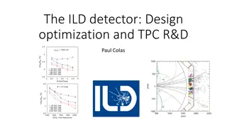
R&D and Simulations on Gain Stability and IBF for ALICE GEM-TPC Upgrade
The research and development efforts, along with simulations, focus on enhancing gain stability and addressing issues related to Ion Back Flow (IBF) for the ALICE GEM-TPC upgrade. Detailed outline, status updates, and major challenges are discussed, highlighting the significance of the upgrade for improved performance in ALICE experiments. Collaborative efforts at CERN and universities, combined with experimental setups and simulations, play a crucial role in achieving the desired goals for the upgrade.

Uploaded on Sep 23, 2024 | 3 Views
Download Presentation

Please find below an Image/Link to download the presentation.
The content on the website is provided AS IS for your information and personal use only. It may not be sold, licensed, or shared on other websites without obtaining consent from the author.If you encounter any issues during the download, it is possible that the publisher has removed the file from their server.
You are allowed to download the files provided on this website for personal or commercial use, subject to the condition that they are used lawfully. All files are the property of their respective owners.
The content on the website is provided AS IS for your information and personal use only. It may not be sold, licensed, or shared on other websites without obtaining consent from the author.
E N D
Presentation Transcript
1 R&D and simulations on gain stability and IBF for the ALICE GEM-TPC upgrade Taku Gunji Center for Nuclear Study The University of Tokyo For the ALICE TPC Upgrade Collaboration RD51 mini week at CERN, Dec. 3-5, 2012
2 Outline ALICE GEM-TPC upgrade R&D Status of gain stability R&D Status of Ion back Flow Simulation study of Ion Back Flow Summary and Outlook
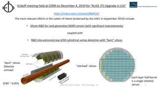
3 ALICE GEM-TPC Upgrade LoI of the ALICE upgrade https://cdsweb.cern.ch/record/1475243/files/LHCC-I-022.pdf Endorsed by the LHCC High rate capability Target: 2MHz in p-p and 50kHz in Pb-Pb collisions Plan for the ALICE-TPC upgrade No gating grid and continuous readout Inherited the idea from PANDA GEM-TPC [arXiv:1207.0013] MWPC readout will be replaced with GEM. Ne(90)/CO2(10) Ed=0.4kV/cm ' @ D =E& OL=& - ( 9#"%)& & & , - '. /012' ' 5#' L; *:)#K & OX & H- 8c7 & C & 8)Q& OL=& #)"%; - :& V+"GN)#*& Q7 :+& :#7 ( $ )& HE1 *& C & #)d- 7 #)%& 2 +( !Q<*R!S;+3 !_D J >a& $ 7 G7 :& ; ?& 4X 3Y` & 7 8& #)"V+& C & ( #; :; :B( )& :)*:*& ":& LP& "8%& 7 8& ' @ D =E& V"A)#8& - 8%)#& & & & & ( #)( "#"M ; 8& _3453i345W a& C & 8)Q& )$ )V:#; 87 V*& ?; #& V; 8M 8- ; - *& #)"%; - :& 8))%)%& & !& G"c; #& Rz <& ){ ; #:& *:"#:)%& & 20 ! "#"$ %& ' ( ( )$ *+, - *)#.& / - "#0& 1 "2)#& 3453.& 6 "*+7 89:; 8& <=&
4 ALICE GEM-TPC Upgrade Major issues for the GEM-TPC upgrade dE/dx resolution for the particle identification ~5% for Kr by PANDA GEM-TPC. Beamtest of prototype GEM-TPC at CERN PS-T10 Detailed presentation by P. Gasik Electronics (PCA16+ALTRO: loan from the LCTPC. Thanks!!) & RCU TPC Gas Vessel & GEM-Stack very preliminary of dE/dx for /e (no calibration, no tracking)
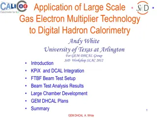
5 ALICE GEM-TPC Upgrade Major issues for the GEM-TPC upgrade Stability of GEM (gain, charge up, discharge, P/T) Measurements in the lab. Test with the prototype at ALICE cavern in 2013. (p-Pb) Ion back flow to avoid space-charge distortion Requirement < 0.25% Test bench in CERN, Munich, and Tokyo Simulations to search for the optimal solutions Experimental setup Sr source Vdr 9mm Vt1 Vb1 Vt2 Vb2 GEM-1 3mm GEM-2 3mm Vbp Gas chamber Overall gas gain ~900 4
6 R&D of gain stability Measurement setup Single wire chamber as reference Monitor humidity Sr sources V. Peskov J. Reinink Experimental setup Vdr 9mm Vt1 Vb1 Vt2 Vb2 GEM-1 3mm GEM-2 3mm Vbp Gas chamber Sealed shielding box flushed with N2, containing GEM Single wire chamber used as reference Single/double GEM gain~900-2000 Current density ~ 2-7nA/cm2 Overall gas gain ~2000 12 Mass flow meters Hygro- meter Single-wire chamber GEM PC NIM CAMAC PC
7 Gain stability 2 GEMs (cylindrical holes) in Ar/CO2(10). Sr90source 4-5% variation of GEM and wire chamber current 4-5% variation was compatible with temperature variation (T=23~24.5). Gain stays stable to within 1% after a few hours Humidity: 56-73 ppm. Gain~900 & current density~1.8nA/cm2 GEM current/Wire chamber current
8 Gain stability Gain~2000 & current density ~ 7nA/cm2 Stability is ~3% Next is to measure stability with 3 GEMs under Ne/CO2
9 Ion back Flow High rate operation (50kHz), continuous readout (no gating grid), and online calibration/clustering Need to minimize field distortion by back drifting ions Target: IBF ~ 0.25% at gain 1000-2000 Direction of IBF R&D Use standard GEMs and optimize by asymmetric electric field Use exotic GEMs (Flower GEM, Cobra GEM, MHSP) Simulations to search for optimal solutions S&)7+$ 7@ )(' +$ A^U $ ' ):>$ 2333[$ :=>$ D)7E$ a=X$ 30 2M Z $ ' ):>$ 2333[$ :=>$ D)7E$ a=X$ 30 M Z $ S<+?)>$ ] =66+' ' +($
10 Measurement at CERN/TUM/CNS Systematic measurement of IBF Using 3 layers of standard GEMs Rate and gain dependence under various field configurations Setup at CERN (RD51-Lab.), TUM, and CNS Various rate of X-ray gun Simultaneous measurement of IBF/energy resolution (TUM/CNS) Readout currents from all electrodes (TUM) !73 8% &@ $ # -A-$ BC 0(D$ % 51&$ $ "74$ % (04&% E $ 3 (-A.D$ F!$ G$ 99@ &H$ Drift plane =&% 58$ TUM: Technical University Munchen CNS: Center for Nuclear Study, Univ. of Tokyo I 0-J $ 0&4-/A >: 3 3 BC 0(D ! E GEM1 K< 93 3 GEM2 K9 93 3 GEM3 LAM 56N/A$ 0&4-/A ?3 3 !"$ O&.M $ 6/AO450(N/A$ ""K<$ G$ "K9$ G$ "L$ G$ ?P : @ HQ 63 $ $ ""M 0-J$ G$ R: : HQ 63 $ !) 500&A% '$ (% $ 0&(M /5% $ 8(M '$ S $ M 0-J $ 8.(A&$ (0&$ 3 &('50&M P $ PADs 7
11 Rate dependence of IBF Changing X-ray tube current and absorber filter Covering charge density= 1000-40000nA/(10cm2) Clear rate dependence on IBF (0.1%~1%) Absorption of ions at GEM3 gets larger for higher rate 5('. *& >0#& 2 ($-. #(2 (+'- !E. #'4(#& -'. ) % & '0& 1 +F(-@ 3$'(& '4(& ,$. -(& 0>& !"#$% & #$'(& ) (*(+) (+,(& 0>& ? GE& -H0--1 6I(& ,$. -(-& ; JK(,02 61 +$@ 0+& 9J5*$,(& ,4$#3(& <JL '4(#& (M (,'-N& !5'$+) $#) & ,0+O3. #$@ 0+& & -P$-Q & B#"RL9& S7: & <: T& -!"#$% & *0-1 @ 0+& U& VJ: ,2 & $60F(& '0*& PW X & -W) #1 D& U& : JVYZ[,2& & -W=;& U& <YZ[,2 & -W=9& U& <J\YZ[,2 & -W? +)& U& \YZ[,2 & -ZP;& U& ZP9& U& ZP<& U& <] : Z& -P$1 +^9\: : & Drift plane Due to space charge? C#1 D& #(31 0+ A: 2 2 Y. Yamaguchi C. Garabatos !"#$% GEM1 =#$+->(#& #(31 0+; 92 2 GEM2 =#$+->(#& #(31 0+9 92 2 Ar(70)/CO2(30) GEM3 <2 2 ? +) . ,@ 0+& #(31 0+ B
12 X-ray position dependence Changing X-ray position from top of GEM1 Different local charge density due to diffusion IBF gets better for smaller distance between X-ray and GEM1 top ( larger local charge density). Due to space charge? Ar(70)/CO2(30) Rate dependence for 4cm case
13 Drift space dependence Changing drift space from 80mm to 3mm. Different interaction rate Clear difference in IBF due to different interaction rate. IBF gets better for larger interaction rate. IBF=2~5% for lower rate (not so much dependeing on rate). Ar(70)/CO2(30)
14 VGEMdependence 5('. *& >0#& 2 ($-. #(2 (+'- VGEMdependence for different drift space IBF depends on VGEM. Steeper dependence for 80mm case. (even if rate dependence is small for 3mm, VGEMdependence is visible..) !E. #'4(#& -'. ) % & '0& 1 +F(-@ 3$'(& '4(& ,$. -(& 0>& !"#$% & #$'(& ) (*(+) (+,(& 0>& ? GE& -H0--1 6I(& ,$. -(-& ; JK(,02 61 +$@ 0+& 9J5*$,(& ,4$#3(& <JL '4(#& (M (,'-N& !5'$+) $#) & ,0+O3. #$@ 0+& & -P$-Q & B#"RL9& S7: & <: T& -!"#$% & *0-1 @ 0+& U& VJ: ,2 & $60F(& '0*& PW X & -W) #1 D& U& : JVYZ[,2& & -W=;& U& <YZ[,2 & -W=9& U& <J\YZ[,2 & -W? +)& U& \YZ[,2 & -ZP;& U& ZP9& U& ZP<& U& <]: Z& -P$1 +^9\: : & Drift plane Due to space charge? C#1 D& #(31 0+ A: 2 2 !"#$% GEM1 =#$+->(#& #(31 0+; 92 2 GEM2 Ar(70)/CO2(30) =#$+->(#& #(31 0+9 92 2 GEM3 <2 2 ? +) . ,@ 0+& #(31 0+ B
15 Space charge and IBF Simulation study by garfield simulation. Presented at the last RD51 meeting on Oct. 2012. Put many Ions above GEM1 (Ed=0.4kV/cm) IBF strongly depends on Nions(>104). Space charge may play an important role for IBF. T. Gunji Ions at [0, 100um] above GEM1 Nions=104 Nions=0, 102, 103, 104, 2x10⁴ Nions=105
16 Space charge and IBF More dynamical simulations by garfield (2 GEMs). Presented at the last RD51 meeting on Oct. 2012. Make spatial profiles of ions created by avalanches for 10usec (100kHz) and 100usec (10kHz) separated seeds. Ion profile per one seed (Ar/CO2=70/30, Gain~1000) Ed = 0.4kV/cm Ed = 0.4kV/cm Et = 3kV/cm Et = 3kV/cm 10usec spacing for avalanches 100usec spacing for avalanches electron electron
17 Space charge and IBF IBF vs. rate (time separation between 2 coming seeds) Rate/hole=10-50kHz in the lab. and less than 1kHz for LHC Pb- Pb 50kHz collisions IBF strongly depends on rate, gain, and # of seeds/hole in case of high rate operations. Qualitatively consistent with the measurements. Seed/hole=25 Seed/hole=10 Seed/hole=3
18 IBF from TUM (lower rate) Reading currents from all electrodes. 3mm as drift space. X-ray tube with 2mm collimator. Pad current ~ 5uA(<< current at CERN measurements.) No strong rate dependence (may be due to low rate and less space charge). IBF = 2-4% A, Honle K. Eckstein M. Ball S. Dorheim B. Ketzer Ar(70)/CO2(30)
19 IBF from TUM (lower rate) Reading currents from all electrodes. 3mm as drift space. No collimator. No strong rate dependence (might be due to lower rate, much less space-charge). IBF = 7% Ar(70)/CO2(30)
20 Different field configurations Lowering ET2and high ET1 0.8% of IBF in Ar/CO2with ET2=0.16kV/cm and ET1= 6kV/cm (Ed=0.25kV/cm) IBF=3-5% for Ne/CO2 ET1cannot be so high. Adding N2to achieve high ET1? Scale=1.07 Scale=1.0 gain=600~2000 gain=2000~6000
21 IBF for various GEM configurations T. Gunji Search for optimal solutions for IBF by simulations 2GEM standard (same GEMs) 3GEM standard 2GEM, low Et (50V/cm) 3GEM, low Et2 (50V/cm)&VGEM2 (for various VGEM1/VGEM3) Large pitch GEM1 + standard GEM2 (Flower GEM structure) Large pitch GEM1 + standard GEM2 & GEM3 2 layers of cobra GEMs 3 layers of cobra GEMs More studies are on going. (higher gain, combination of different geometry, etc )
22 Summary and Outlook R&D of gain stability and ion back flow are on-going. Gain stability <3% (2 GEMs, higher gain and rate) Stability of 3 GEMs will be studied under Ne/CO2. IBF depends on rate of X-ray, spread of seed electrons (diffusion), and gain of GEM under high rate conditions. Space charge plays an important role for IBF under high rate. This is (partially) confirmed by garfield simulations. Under low rate, IBF is 2-5% with 3 standard GEMs. Try to reduce IBF further: More study on asymmetric field configurations Use standard GEMs with different geometry (hole size, pitch) Use exotic GEMs (Thick COBRA GEM, Flower GEM) Simulation studies are on-going.
23 Backup slides
24 R&D of gain stability Correlation 10