Caterpillar Cat 350 350L TRACK-TYPE EXCAVATOR (Prefix 7RK) Service Repair Manual Instant Download
Please open the website below to get the complete manualnn//
Download Presentation

Please find below an Image/Link to download the presentation.
The content on the website is provided AS IS for your information and personal use only. It may not be sold, licensed, or shared on other websites without obtaining consent from the author. Download presentation by click this link. If you encounter any issues during the download, it is possible that the publisher has removed the file from their server.
E N D
Presentation Transcript
w 1/24(W) Shutdown SIS Previous Screen Product: EXCAVATOR Model: 350-A EXCAVATOR 7RK Configuration: 350 350L TRACK-TYPE EXCAVATORS 7RK00001-UP (MACHINE) POWERED BY 3306 ENGINE Disassembly and Assembly 350 AND 350 L EXCAVATOR MACHINE SYSTEMS Media Number -SENR6148-04 Publication Date -01/11/2004 Date Updated -12/03/2010 SENR61480038 Swing Motor (Right) SMCS - 5058-010; 5058-015; 5058-016; 5058 Remove & Install Swing Motor (Right) Start By: a. remove swing control valve NOTE: To prevent oil loss and to keep dirt and debris out of the hydraulic system, put plugs in all hose assemblies as they are being disconnected. 1. Disconnect five hose assemblies (1) at the boom. Move the hose assemblies clear of the right hand swing motor. 2. Put identification marks on four hose assemblies (2) that are connect to the right hand swing motor for installation purposes. Disconnect the hose assemblies from the right hand swing motor. https://127.0.0.1/sisweb/sisweb/techdoc/techdoc_print_page.jsp?returnurl=/sisweb/siswe... 2022/3/6
w 2/24(W) 3. Fasten a lifting sling and a hoist to right hand swing motor (3) as shown. Remove four socket head bolts (4) that hold the right hand swing motor to the swing drive. Carefully remove the right hand swing motor from the swing drive. The weight of the right hand swing motor is 64 kg (140 lb). 4. Remove the O-ring seal from the right hand swing motor. NOTE: The following steps are for the installation of the right hand swing motor. 5. Make sure the mating surfaces of the right hand swing motor and the right hand swing drive are thoroughly clean. 6. Check the condition of the O-ring seal used on the right hand swing motor and in the hose assemblies that connect to the right hand swing motor. If any of the seals are damaged, use new parts for replacement. 7. Install the O-ring seal on the right hand swing motor. 8. Install the right hand swing motor in the reverse order of removal. NOTICE Make sure the right hand swing motor is filled with clean hydraulic oil to the fill port before operation. 9. Fill the hydraulic oil tank with oil to the correct level. Refer to the 350 & 350 L Excavators Operation & Maintenance Manual for the correct filling procedure. End By: a. install swing control valve Disassemble Swing Motor (Left & Right) https://127.0.0.1/sisweb/sisweb/techdoc/techdoc_print_page.jsp?returnurl=/sisweb/siswe... 2022/3/6
w 3/24(W) Start By: a. remove swing motor (left or right) NOTE: The disassembly procedure which follows is for both the left and right swing motors. 1. Make sure the outside of the swing motor is clean and free of dirt and debris prior to disassembly. Typical Example 2. Put the swing motor on wood blocks as shown. The weight of the swing motor is 64 kg (140 lb). Put identification marks on each relief valve assembly (1) as to its location in the swing motor. Remove two relief valve assemblies (1). 3. Remove the brake valve group from the body of the swing motor. 4. Remove the cushion crossover relief valve group from the head of the swing motor. https://127.0.0.1/sisweb/sisweb/techdoc/techdoc_print_page.jsp?returnurl=/sisweb/siswe... 2022/3/6
https://www.ebooklibonline.com Hello dear friend! Thank you very much for reading. Enter the link into your browser. The full manual is available for immediate download. https://www.ebooklibonline.com
w 4/24(W) 5. Remove O-ring seal (3) and back-up ring (2) from each relief valve assembly. NOTE: For the disassembly procedure for relief valve assemblies (1), see Steps 25a through 25m. For the disassembly procedure for the brake valve group, see Steps 26a through 26e. For the disassembly of the cushion crossover relief valve group, see Steps 27a through 27d. NOTICE Put identification marks on the components of each make-up valve (4) as they are removed from the head of the swing motor. The components of each make-up valve must be reinstalled in their original locations. 6. Remove two make-up valves (4) from the head of the swing motor. Remove plugs (7), springs (6) and valves (5). Remove O-ring seal (8) from each plug (7). https://127.0.0.1/sisweb/sisweb/techdoc/techdoc_print_page.jsp?returnurl=/sisweb/siswe... 2022/3/6
w 5/24(W) 7. Put an alignment mark on head (10) so it can be reinstalled in its original position on the swing motor body. 8. Remove four socket head bolts (9) and head (10) from the swing motor body. 9. Remove O-ring seal (11) and bearing (12) from the head. If necessary, remove two pins (13) from the head. 10. Remove 20 springs (14) from the piston. 11. Remove plate (15) from the barrel assembly. https://127.0.0.1/sisweb/sisweb/techdoc/techdoc_print_page.jsp?returnurl=/sisweb/siswe... 2022/3/6
w 6/24(W) NOTE: When Tooling (A) is installed to remove piston (16), install the threaded rods into holes (X) as shown. 12. Mark the position of piston (16) in the swing motor body for assembly purposes. Install Tooling (A) in piston (16) as shown. Remove piston (16) from the swing motor body with Tooling (A). 13. Remove three separator plates and two friction plates (17) from the piston. NOTICE During removal of barrel assembly (18) from swing motor body, do not let the components come apart. All parts in the barrel assembly must be reinstalled in their original locations. 14. Put the swing motor on its side as shown. Remove barrel assembly (18) from the shaft in body (19). https://127.0.0.1/sisweb/sisweb/techdoc/techdoc_print_page.jsp?returnurl=/sisweb/siswe... 2022/3/6
w 7/24(W) 15. Disassemble barrel assembly (18) as follows: a. Put identification marks on nine piston assemblies (20) as to their location in plate (21) and barrel (22). Remove nine piston assemblies (20) andplate (21), as a unit, from barrel (22). Separate the piston assemblies from the plate. b. Remove bushing (23) from the barrel. Remove the spacer from the bushing. NOTE: There are 12 pins (24) in barrel (22). Two pins are used in each hole location. c. Remove 12 pins (24) from the barrel. There is spring force against spacer (26). When retaining ring (25) is removed, the spring force will be released. To prevent possible personal https://127.0.0.1/sisweb/sisweb/techdoc/techdoc_print_page.jsp?returnurl=/sisweb/siswe... 2022/3/6
w 8/24(W) injury, removal of the internal components in barrel (22) should be performed in a press in order to retain spring (27) and spacer (26). NOTICE Spacer (26) and spacer (28) are different in size. Put identification marks on the two spacers as they are removed so they can be reinstalled in their original locations. d. Put barrel (22) in a press. Install a suitable size piece of rectangular steel bar stock against spacer (26). Put a slight amount of compression on spacer (26) with the press. Remove retaining ring (25), and slowly release the spring compression. Remove spacer (26), spring (27) and spacer (28) from barrel (22). 16. Remove O-ring seals (29) and (30) from the body. 17. Remove retaining ring (31) that holds shaft assembly (32) in the body. 18. Use a soft faced hammer to remove shaft assembly (32) and retainer (33) from the body. Remove the shaft assembly in the direction shown. https://127.0.0.1/sisweb/sisweb/techdoc/techdoc_print_page.jsp?returnurl=/sisweb/siswe... 2022/3/6
w 9/24(W) 19. Remove plate (34) from the body. It may be necessary to use a hammer and punch to remove the plate. 20. Remove ring (35) and retainer (33) from the shaft. 21. Remove oil seal (36) from front cover (33). 22. Remove retaining ring (37) and bearing race (39) from the end of the shaft. 23. Remove two retaining rings (40) and the spacers (one on each side of the bearing) that position bearing (38) on the shaft. 24. Put the shaft in a press. Press the shaft out of bearing (38). 25. Disassemble relief valves (1) as follows: https://127.0.0.1/sisweb/sisweb/techdoc/techdoc_print_page.jsp?returnurl=/sisweb/siswe... 2022/3/6
w 10/24(W) a. Remove plug (41). b. Remove O-ring seal (42) and back-up ring (43) from the plug. c. Remove spring (44). d. Remove seat (45). https://127.0.0.1/sisweb/sisweb/techdoc/techdoc_print_page.jsp?returnurl=/sisweb/siswe... 2022/3/6
w 11/24(W) e. Remove locknut (46). f. Remove body (47). g. Remove retainer (48). h. Remove ball (49) from the larger of the two holes in the body. i. Remove insert (50) and insert (51) from body (47). j. Remove back-up ring (52) and O-ring seal (53) from body (47). https://127.0.0.1/sisweb/sisweb/techdoc/techdoc_print_page.jsp?returnurl=/sisweb/siswe... 2022/3/6
w 12/24(W) k. Remove spring (54) from body (55). l. Remove retainer (56) from the body. m. Remove valve (57) from the body. https://127.0.0.1/sisweb/sisweb/techdoc/techdoc_print_page.jsp?returnurl=/sisweb/siswe... 2022/3/6
w 13/24(W) 26. Disassemble the brake valve group as follows: a. Remove O-ring seals (64) and O-ring seal (67) from the valve body. b. Remove spring (65) and spool (60) from the valve body. c. Remove spring (66) and spool assembly (61) from the valve body. d. Remove ball (62) from the valve body. e. Remove plug (63) from the valve body. 27. Disassemble the cushion crossover relief valve group as follows: a. Remove spring (68) from valve body (71). b. Remove ring (74), O-ring seal (75) and ring (76) from valve body (71). c. Remove plug (73) from valve body (71). Remove O-ring seal (72) from the plug. d. Remove shims (77), the spool assembly and springs (69) and (70) from valve body (71). Assemble Swing Motor (Left & Right) NOTE: The assembly procedure which follows is for both the left and right swing motors. https://127.0.0.1/sisweb/sisweb/techdoc/techdoc_print_page.jsp?returnurl=/sisweb/siswe... 2022/3/6
w 14/24(W) 1. Make sure all parts of the swing motor are clean and free of dirt and debris prior to assembly. Check the condition of all parts in the swing motor. Guideline For Reusable Parts "Piston Pumps And Motors", Form No. SEBF8032-01 can be used as a guide for reconditioning and determining the reusability of some parts. 2. Check the condition of all O-ring seals and back-up rings used in the swing motor and the relief valves. If any of the seals are damaged, use new parts for replacement. 3. Assemble the cushion crossover relief valve as follows: a. Install springs (70) and (69), the spool assembly and shims (77) in valve body (71). b. Install O-ring seal (72) on plug (73). Install plug (73) in valve body (71). Tighten the plug to a torque of 147.2 10 N m (110 7 lb ft). c. Install spring (68) in valve body (71). https://127.0.0.1/sisweb/sisweb/techdoc/techdoc_print_page.jsp?returnurl=/sisweb/siswe... 2022/3/6
w 15/24(W) 4. Assemble the brake valve group as follows: a. Install plug (63) in the valve body. b. Install ball (62) in the valve body. c. Install spool assembly (61) and spring (66) in the valve body. d. Install spool (60) and spring (65) in the valve body. e. install O-ring seals (67) and (64) in the valve body. 5. Assemble relief valves (1) as follows: a. Install valve (57) in the body as shown. b. Install retainer (56) on the body as shown. c. Install spring (54) in body (55). https://127.0.0.1/sisweb/sisweb/techdoc/techdoc_print_page.jsp?returnurl=/sisweb/siswe... 2022/3/6
w 16/24(W) d. Install back-up ring (52) and O-ring seal (53) on body (47). Make sure the seal and ring are in the positions shown. e. Install insert (51) and insert (50) in body (47) as shown. f. Install ball (49) in the larger of the two holes in body (47). g. Install retainer (48) on the body assembly as shown. h. Install body (47). https://127.0.0.1/sisweb/sisweb/techdoc/techdoc_print_page.jsp?returnurl=/sisweb/siswe... 2022/3/6
w 17/24(W) i. Install locknut (46) in body (47). Locknut (46) must be tightened to a torque of 160 30 N m (120 22 lb ft) after adjustment of the valve is made. j. Install seat (45) as shown. k. Install spring (44). l. Install O-ring seal (42) and back-up ring (43) on plug (41) as shown. https://127.0.0.1/sisweb/sisweb/techdoc/techdoc_print_page.jsp?returnurl=/sisweb/siswe... 2022/3/6
w 18/24(W) m. Install plug (41) in relief valve (1). Plug (41) must be tightened to a torque of 120 10 N m (90 7 lb ft). NOTE: To adjust the pressure settings of each relief valve (1), refer to the 350 And 350 L Excavators Hydraulic System Testing & Adjusting module. 6. Install one of the retaining rings (40) on the drive shaft. 7. Press the drive shaft into bearing (38) until it makes contact with the retaining ring. Install the other retaining ring (40) on the other side of the bearing. 8. Install bearing race (39) and retaining ring (37) on the end of the drive shaft. 9. Install oil seal (36) in front cover (33) with tool (A). Install the seal so the lip will be facing away from the outside of the front cover, and until it makes contact with the counterbore in the front cover. 10. Install shaft assembly (32) in the body. Make sure bearing (38) is seated in the counterbore in the body. 11. Lubricate the lip of oil seal (36) with clean hydraulic oil. Install front cover (33) over shaft assembly (32) and into the body with a soft faced hammer. https://127.0.0.1/sisweb/sisweb/techdoc/techdoc_print_page.jsp?returnurl=/sisweb/siswe... 2022/3/6
w 19/24(W) 12. Install retaining ring (31) that holds the shaft assembly in plate. Install ring (35) on shaft assembly (32). 13. Put a thin coat of 5P-0960 Multipurpose Grease on the back side of plate (34). Install plate (34) in the body. 14. Install O-ring seals (29) and (30) in the body as shown. 15. Assemble barrel assembly (18) as follows: a. Install spacer (28), spring (27) and spacer (26) in barrel (22). Put the barrel in a press. Install a suitable size piece of rectangular steel bar stock on spacer (26), and compress spring (27) until retaining ring (25) can be installed. Install retaining ring (25). b. Install 12 pins (24) in barrel (22). https://127.0.0.1/sisweb/sisweb/techdoc/techdoc_print_page.jsp?returnurl=/sisweb/siswe... 2022/3/6
w 20/24(W) c. Install the spacer in bushing (23). Install bushing (23) on pins (24). d. Put clean hydraulic oil on nine piston assemblies (20). Install the piston assemblies in their original bores in plate (21). Install the plate with the piston assemblies in their original bores in barrel (22). NOTICE Do not let the barrel assembly fall apart when it is installed in the body. 16. Put body (19) on its side. Install barrel assembly (18) in the body. https://127.0.0.1/sisweb/sisweb/techdoc/techdoc_print_page.jsp?returnurl=/sisweb/siswe... 2022/3/6
w 21/24(W) NOTICE The four tooth cut locations of each friction plate must be in alignment. Also, the four tooth cut locations of each separator plate must be in alignment in the body. 17. Put clean hydraulic oil on three separator plates and two friction plates (17). Install the plates in alternating order in the body. Start with a separator plate, and end with a separator plate. 18. Install piston (16) in the body in its original position. Threaded holes (X) can be used as a guide during installation. If the piston is hard to install because of O-ring seal resistance, a soft faced hammer can be used as an aid in installation. 19. Install 20 springs (14) in the piston. 20. Install two pins (13) and bearing (12) in head (10). 21. Install O-ring seal (11) on head (10). https://127.0.0.1/sisweb/sisweb/techdoc/techdoc_print_page.jsp?returnurl=/sisweb/siswe... 2022/3/6
w 22/24(W) 22. Put a thin coat of 5P-0960 Multipurpose Grease on the face of plate (15) that makes contact with the head. The grease will hold the plate to the head. Install the plate on the head in its original position as shown in the illustration. 23. Put head (10) in its original position on the body. Install four socket head bolts (9) that hold it. Tighten the socket head bolts to a torque of 430 43 N m (320 32 lb ft). https://127.0.0.1/sisweb/sisweb/techdoc/techdoc_print_page.jsp?returnurl=/sisweb/siswe... 2022/3/6
w 23/24(W) NOTICE Make sure to install each make-up valve (4) in its original position in the head. 24. Install two make-up valves (4) in the head. Install O-ring seals (8) on plugs (7). Install valves (5), springs (6) and plugs (7). Tighten plugs (7) to a torque of 220 25 N m (160 18 lb ft). NOTICE Make sure to install each relief valve assembly (1) in its original position in the head. 25. Install back-up ring (2) and O-ring seal (3) on each relief valve assembly (1) as shown in Photo C48291P1. 26. Install relief valve assemblies (1) in the head. Tighten the relief valve assemblies to a torque of 180 10 N m (135 7 lb ft). 27. Reinstall the cushion crossover relief valve in the head of the swing motor. https://127.0.0.1/sisweb/sisweb/techdoc/techdoc_print_page.jsp?returnurl=/sisweb/siswe... 2022/3/6
w 24/24(W) 28. Reinstall the brake valve group on the swing motor. NOTICE To prevent damage to the swing motor, the unit must be filled with hydraulic oil to the fill port prior to operation. Refer to the 350 & 350 L Excavators Operation & Maintenance Manual for the correct filling procedure. End By: a. install swing motor (left or right) Copyright 1993 - 2022 Caterpillar Inc. Sun Mar 6 10:44:15 UTC+0800 2022 All Rights Reserved. Private Network For SIS Licensees. https://127.0.0.1/sisweb/sisweb/techdoc/techdoc_print_page.jsp?returnurl=/sisweb/siswe... 2022/3/6
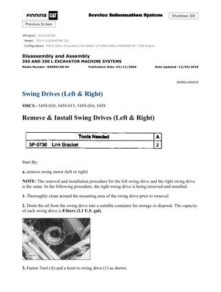
w 1/13(W) Shutdown SIS Previous Screen Product: EXCAVATOR Model: 350-A EXCAVATOR 7RK Configuration: 350 350L TRACK-TYPE EXCAVATORS 7RK00001-UP (MACHINE) POWERED BY 3306 ENGINE Disassembly and Assembly 350 AND 350 L EXCAVATOR MACHINE SYSTEMS Media Number -SENR6148-04 Publication Date -01/11/2004 Date Updated -12/03/2010 SENR61480039 Swing Drives (Left & Right) SMCS - 5459-010; 5459-015; 5459-016; 5459 Remove & Install Swing Drives (Left & Right) Start By: a. remove swing motor (left or right) NOTE: The removal and installation procedure for the left swing drive and the right swing drive is the same. In the following procedure, the right swing drive is being removed and installed. 1. Thoroughly clean around the mounting area of the swing drive prior to removal. 2. Drain the oil from the swing drive into a suitable container for storage or disposal. The capacity of each swing drive is 8 liters (2.1 U.S. gal). 3. Fasten Tool (A) and a hoist to swing drive (1) as shown. https://127.0.0.1/sisweb/sisweb/techdoc/techdoc_print_page.jsp?returnurl=/sisweb/siswe... 2022/3/6
w 2/13(W) 4. Remove 20 bolts (2) and the washers that hold the swing drive in position. Remove the two corks from the forcing screw holes in the swing drive housing. Install suitable size forcing screws in the threaded forcing screw holes. Tighten the forcing screws evenly to separate the swing drive from the main frame. 5. Remove swing drive (1) from the machine. The weight of the swing drive is 308 kg (680 lb). NOTE: The following steps are for the installation of the swing drive. 6. Thoroughly clean the mating surfaces of the main frame and the swing drive housing. 7. Put 5P-3931 Anti-Seize Compound on the locating dowel in the main frame. 8. Put 1U-8846 Gasket Maker on the mating surface of the main frame and the swing drive housing. NOTE: During installation, the locating dowel for the swing drive may come out of the swing drive housing. 9. Fasten Tool (A) and a hoist to swing drive (1). Put the swing drive in its original position in the main frame. If the locating dowel comes out of the swing drive housing, it can be reinstalled with a hammer after the swing drive is in place. 10. Put 9S-3263 Thread Lock on the threads of 20 bolts (2). Install the 20 bolts and washers that hold the swing drive in position. Reinstall the two corks in the forcing screw holes in the swing drive housing. 11. After installation of the swing motor, fill the hydraulic oil tank and the swing drive with oil to the correct level. Refer to the 350 & 350 L Excavators Operation & Maintenance Manual for the correct filling procedures. End By; a. install swing motor (left or right) Disassemble Swing Drive (Left & Right) Start By: a. remove swing drive (left or right) https://127.0.0.1/sisweb/sisweb/techdoc/techdoc_print_page.jsp?returnurl=/sisweb/siswe... 2022/3/6
Suggest: If the above button click is invalid. Please download this document first, and then click the above link to download the complete manual. Thank you so much for reading
w 3/13(W) NOTE: The disassembly procedure which follows is for both the left and right swing drives. 1. Fasten the swing drive to Tool (A) as shown. The weight of the swing drive is 308 kg (680 lb). 2. Put an alignment mark on the cover, ring gear and main housing of the swing drive for assembly purposes. 3. Remove 16 bolts (1) and the washers that hold cover (2) to the ring gear and housing of the swing drive. 4. Fasten Tool (B) and a hoist to cover (2). Remove the cover. The weight of the cover is 16 kg (35 lb). 5. Remove sun gear (3) from the carrier assembly. 6. Remove carrier assembly (4). 7. Disassemble carrier assembly (4) as follows: https://127.0.0.1/sisweb/sisweb/techdoc/techdoc_print_page.jsp?returnurl=/sisweb/siswe... 2022/3/6
https://www.ebooklibonline.com Hello dear friend! Thank you very much for reading. Enter the link into your browser. The full manual is available for immediate download. https://www.ebooklibonline.com


