Caterpillar Cat 350 and 350 L Excavator (Prefix 3ML) Service Repair Manual Instant Download
Please open the website below to get the complete manualnn//
Download Presentation

Please find below an Image/Link to download the presentation.
The content on the website is provided AS IS for your information and personal use only. It may not be sold, licensed, or shared on other websites without obtaining consent from the author. Download presentation by click this link. If you encounter any issues during the download, it is possible that the publisher has removed the file from their server.
E N D
Presentation Transcript
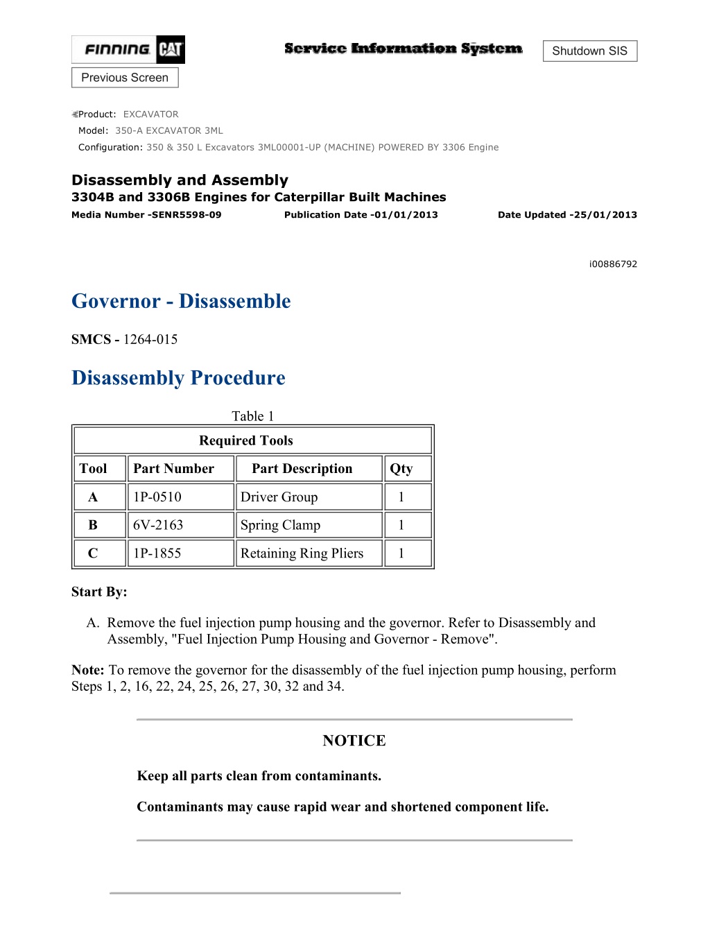
350 & 350 L Excavators 3ML00001-UP (MACHINE) POWERED BY 3306 Engine(S... 1/12 Shutdown SIS Previous Screen Product: EXCAVATOR Model: 350-A EXCAVATOR 3ML Configuration: 350 & 350 L Excavators 3ML00001-UP (MACHINE) POWERED BY 3306 Engine Disassembly and Assembly 3304B and 3306B Engines for Caterpillar Built Machines Media Number -SENR5598-09 Publication Date -01/01/2013 Date Updated -25/01/2013 i00886792 Governor - Disassemble SMCS - 1264-015 Disassembly Procedure Table 1 Required Tools Tool Part Number Part Description Qty A 1P-0510 Driver Group 1 B 6V-2163 Spring Clamp 1 C 1P-1855 Retaining Ring Pliers 1 Start By: A. Remove the fuel injection pump housing and the governor. Refer to Disassembly and Assembly, "Fuel Injection Pump Housing and Governor - Remove". Note: To remove the governor for the disassembly of the fuel injection pump housing, perform Steps 1, 2, 16, 22, 24, 25, 26, 27, 30, 32 and 34. NOTICE Keep all parts clean from contaminants. Contaminants may cause rapid wear and shortened component life. https://127.0.0.1/sisweb/sisweb/techdoc/techdoc_print_page.jsp?returnurl=/sis... 2021/12/23
350 & 350 L Excavators 3ML00001-UP (MACHINE) POWERED BY 3306 Engine(S... 2/12 Illustration 1 g00453006 1. Remove fuel ratio control (1) from governor (2) . Illustration 2 g00453007 Note: Illustration 2 shows the fuel ratio control that is still connected. 2. Remove six bolts (3), two bolts (5), housing (4) and the gasket. Illustration 3 g00453008 https://127.0.0.1/sisweb/sisweb/techdoc/techdoc_print_page.jsp?returnurl=/sis... 2021/12/23
350 & 350 L Excavators 3ML00001-UP (MACHINE) POWERED BY 3306 Engine(S... 3/12 3. Remove governor spring (7), seat (6) and the washers. Illustration 4 g00453009 4. Remove six bolts (8), cover (9) and the gasket. Use Tool (A) in order to remove seal (10) . Illustration 5 g00453010 5. Remove low idle adjustment screw (12) and spring (11) . https://127.0.0.1/sisweb/sisweb/techdoc/techdoc_print_page.jsp?returnurl=/sis... 2021/12/23
https://www.ebooklibonline.com Hello dear friend! Thank you very much for reading. Enter the link into your browser. The full manual is available for immediate download. https://www.ebooklibonline.com
350 & 350 L Excavators 3ML00001-UP (MACHINE) POWERED BY 3306 Engine(S... 4/12 Illustration 6 g00453011 6. Remove shaft assembly (15) and levers (14) and (13) . Illustration 7 g00453012 7. Remove two snap rings (19) from two pins (17). Remove two pins (17). Remove plates (16) and stop (18) . Illustration 8 g00453014 8. Remove pins (21) and (22) and remove spring (20) . https://127.0.0.1/sisweb/sisweb/techdoc/techdoc_print_page.jsp?returnurl=/sis... 2021/12/23
350 & 350 L Excavators 3ML00001-UP (MACHINE) POWERED BY 3306 Engine(S... 5/12 Illustration 9 g00453015 9. Remove two bolts (23), and the washers, and remove adapter (24), the coupling, and the O- ring seal. 10. Remove contact (27) and body (28) with an O-ring seal. 11. Remove two bolts (29) and the washers and remove cover (30) and the gasket. 12. Remove two nuts and washers (26) and remove shutoff solenoid (25) and the gasket. Illustration 10 g00453016 13. Remove shaft (31) and lever (32) . https://127.0.0.1/sisweb/sisweb/techdoc/techdoc_print_page.jsp?returnurl=/sis... 2021/12/23
350 & 350 L Excavators 3ML00001-UP (MACHINE) POWERED BY 3306 Engine(S... 6/12 Illustration 11 g00453017 Note: The check valve will be damaged during removal. Remove check valve (33) only if a replacement is necessary. 14. Remove check valve (33) only if a replacement is necessary. Illustration 12 g00453018 15. Remove seal (34) and adjustment screw (35) . https://127.0.0.1/sisweb/sisweb/techdoc/techdoc_print_page.jsp?returnurl=/sis... 2021/12/23
350 & 350 L Excavators 3ML00001-UP (MACHINE) POWERED BY 3306 Engine(S... 7/12 Illustration 13 g00453019 16. Remove bolt (36), housing (37) and the gasket from the fuel injection pump housing. Illustration 14 g00453557 Typical example 17. Remove bolts (38) and remove torque control (39) . 18. Disassemble torque control (39) and inspect the spacer, the spring, and the insulator for damage or wear. Replace parts that are worn or damaged with new parts. Illustration 15 g00453558 19. Remove two bolts (40) and block (41) . https://127.0.0.1/sisweb/sisweb/techdoc/techdoc_print_page.jsp?returnurl=/sis... 2021/12/23
350 & 350 L Excavators 3ML00001-UP (MACHINE) POWERED BY 3306 Engine(S... 8/12 Illustration 16 g00453559 20. Remove the bolt that holds collar (42) to bolt (44). Remove collar (42), spring (43) and bolt (44) . 21. Remove the stop screws from collar (42) if the collar needs to be replaced. Illustration 17 g00453560 22. Remove three bolts (46) and remove governor servo (45). The governor servo must be rotated in order to be released from the rack's regulator. https://127.0.0.1/sisweb/sisweb/techdoc/techdoc_print_page.jsp?returnurl=/sis... 2021/12/23
350 & 350 L Excavators 3ML00001-UP (MACHINE) POWERED BY 3306 Engine(S... 9/12 Illustration 18 g00453632 23. Remove lockring (50), seat (53), link spring (52) and sleeve (51). Remove the other lockring (50) from the groove in the center of valve (47). Remove valve (47), sleeve (48) and piston (49). The piston must be pushed down in order to be removed. Remove the O- ring seal from sleeve (48). Remove pin (55) and lever (56) . Illustration 19 g00453633 Illustration 20 g00453634 24. Use Tool (A) in order to hold spring (58) compressed for the removal of ring (57). Spring (58) is used in order to put a preload on the thrust bearing for the camshaft in the fuel injection pump housing. 25. Remove ring (57) and slowly release Tool (A) . https://127.0.0.1/sisweb/sisweb/techdoc/techdoc_print_page.jsp?returnurl=/sis... 2021/12/23
350 & 350 L Excavators 3ML00001-UP (MACHINE) POWERED BY 3306 Engine... 10/12 Illustration 21 g00453635 26. Remove bearing (60), sleeves (59) and spring (58) . Illustration 22 g00453636 27. Remove ring (61) and dashpot assembly (62) . Illustration 23 g00453637 28. Use Tool (C) in order to remove snap ring (68). Remove ring (67) and spool (66) . https://127.0.0.1/sisweb/sisweb/techdoc/techdoc_print_page.jsp?returnurl=/sis... 2021/12/23
350 & 350 L Excavators 3ML00001-UP (MACHINE) POWERED BY 3306 Engine... 11/12 29. Remove seat (65) from spring (64) and remove spring (64) from seat (63) . Illustration 24 g00453665 30. Remove riser (69) . Illustration 25 g00453667 31. Remove ring (70), races (71) and bearing (72) . https://127.0.0.1/sisweb/sisweb/techdoc/techdoc_print_page.jsp?returnurl=/sis... 2021/12/23
350 & 350 L Excavators 3ML00001-UP (MACHINE) POWERED BY 3306 Engine... 12/12 Illustration 26 g00453668 32. Remove four bolts (73) and carrier (74) . Illustration 27 g00453669 33. Remove dowels (77) and flyweights (76). Remove governor shaft (75) and the dowel that is not shown from shaft (75) . Illustration 28 g00453670 34. Remove races (78) and bearing (79) . Copyright 1993 - 2021 Caterpillar Inc. Thu Dec 23 09:32:29 UTC+0800 2021 All Rights Reserved. Private Network For SIS Licensees. https://127.0.0.1/sisweb/sisweb/techdoc/techdoc_print_page.jsp?returnurl=/sis... 2021/12/23
350 & 350 L Excavators 3ML00001-UP (MACHINE) POWERED BY 3306 Engine(S... 1/17 Shutdown SIS Previous Screen Product: EXCAVATOR Model: 350-A EXCAVATOR 3ML Configuration: 350 & 350 L Excavators 3ML00001-UP (MACHINE) POWERED BY 3306 Engine Disassembly and Assembly 3304B and 3306B Engines for Caterpillar Built Machines Media Number -SENR5598-09 Publication Date -01/01/2013 Date Updated -25/01/2013 i01111261 Governor - Assemble SMCS - 1264-016 Assembly Procedure Table 1 Required Tools Tool Part Number Part Description Qty A 1P-1855 Retaining Ring Pliers 1 B 6V-2163 Spring Clamp 1 C 1P-0510 Driver Group 1 D 6V-2054 Shield Driver 1 Note: Put clean engine oil on all parts before assembly. Ensure that all of the oil passages are clear. Note: Check the condition of the gaskets and the O-ring seals. If the gaskets, the seals, or any parts are worn or damaged, use new parts for replacement. NOTICE Keep all parts clean from contaminants. Contaminants may cause rapid wear and shortened component life. https://127.0.0.1/sisweb/sisweb/techdoc/techdoc_print_page.jsp?returnurl=/sis... 2021/12/23
350 & 350 L Excavators 3ML00001-UP (MACHINE) POWERED BY 3306 Engine(S... 2/17 Illustration 1 g00453799 1. Install one race (1), bearing (2) and the other race (1) on the camshaft in the fuel injection pump housing. Illustration 2 g00453801 2. Put flyweights (4) in position on carrier (3) and install the dowels in order to hold the flyweights in place. The flyweights must move freely on the dowels. Illustration 3 g00453802 https://127.0.0.1/sisweb/sisweb/techdoc/techdoc_print_page.jsp?returnurl=/sis... 2021/12/23
350 & 350 L Excavators 3ML00001-UP (MACHINE) POWERED BY 3306 Engine(S... 3/17 3. Install dowel (5) in governor shaft (6) and install the governor shaft in the carrier (3) . Illustration 4 g00459340 4. Put carrier (3) in position and install bolts (7) . Illustration 5 g00459410 5. Install race (9), bearing (10) and race (9). Use Tool (A) in order to install ring (8) on riser (11) . https://127.0.0.1/sisweb/sisweb/techdoc/techdoc_print_page.jsp?returnurl=/sis... 2021/12/23
350 & 350 L Excavators 3ML00001-UP (MACHINE) POWERED BY 3306 Engine(S... 4/17 Illustration 6 g00459411 6. Install riser (11) . Illustration 7 g00459414 7. Assemble the dashpot, as follows: a. Install spring (13) on seat (12) and install seat (14) in spring (13) . b. Put spool (15) and ring (16) in position on seat (14) and use Tool (A) in order to install snap ring (17) . https://127.0.0.1/sisweb/sisweb/techdoc/techdoc_print_page.jsp?returnurl=/sis... 2021/12/23
350 & 350 L Excavators 3ML00001-UP (MACHINE) POWERED BY 3306 Engine(S... 5/17 Illustration 8 g00459416 8. Install dashpot assembly (19). Install ring (18) in the lower groove in the governor shaft. Illustration 9 g00459419 9. Install sleeve (20), spring (22), sleeve (20) and bearing (21) . Note: Spring (22) is used in order to put a preload on the thrust bearing on the camshaft in the fuel injection pump housing. https://127.0.0.1/sisweb/sisweb/techdoc/techdoc_print_page.jsp?returnurl=/sis... 2021/12/23
350 & 350 L Excavators 3ML00001-UP (MACHINE) POWERED BY 3306 Engine(S... 6/17 Illustration 10 g00459421 10. Use Tool (B) in order to hold spring (22) compressed and install ring (23) in the groove in the governor shaft. Remove Tool (B) . Illustration 11 g00459423 11. Put lever (33) in position on the governor servo and install pin (32) in order to hold the lever in place. Use a hammer and a chisel in order to move the metal (stake) at four places that are spread apart 90 degrees. Perform this procedure on the outside surface on both legs of the governor servo. This helps to hold pin (32) in place. 12. Install the O-ring seal on sleeve (25). Install piston (26) and sleeve (25) . 13. Install valve (24) . 14. Install one lockring (27) in the groove near the center of valve (24). Put sleeve (28), link spring (29) and seat (30) in position on valve (24) and install second lockring (31) . Illustration 12 g00454273 15. Put the governor servo in position on the fuel injection pump housing with piston (34) that is engaged over rack control sleeve (35) and install the bolts that hold the rack control sleeve in place. https://127.0.0.1/sisweb/sisweb/techdoc/techdoc_print_page.jsp?returnurl=/sis... 2021/12/23
350 & 350 L Excavators 3ML00001-UP (MACHINE) POWERED BY 3306 Engine(S... 7/17 Illustration 13 g00591527 3304B engine Note: The 3304B engine has one stop screw (36) and one locknut (38). Illustration 14 g00454274 3306B 16. If the stop screws were removed, install two stop screws (36) in collar (37), as shown. Install locknuts (38) . https://127.0.0.1/sisweb/sisweb/techdoc/techdoc_print_page.jsp?returnurl=/sis... 2021/12/23
350 & 350 L Excavators 3ML00001-UP (MACHINE) POWERED BY 3306 Engine(S... 8/17 Illustration 15 g00454275 17. Install bolt (41) in block (42), as shown. Install spring (40) on bolt (41), as shown. Put collar (37) in position on bolt (41) with the hole in the collar in alignment with the notch in bolt (41) and install bolt (39) in order to hold the collar in place. Illustration 16 g00454428 Illustration 17 g00459548 https://127.0.0.1/sisweb/sisweb/techdoc/techdoc_print_page.jsp?returnurl=/sis... 2021/12/23
350 & 350 L Excavators 3ML00001-UP (MACHINE) POWERED BY 3306 Engine(S... 9/17 18. Put block (42) in position on housing (43). Align the holes in block (42) with the dowels. Tighten two bolts (44) . Illustration 18 g00590080 3304B torque control 19. Assemble the torque control on the 3304B engine. Install retainer (51), two bars (49), spacer (50), contact (46), and insulator (45) in position on bolts (52) . https://127.0.0.1/sisweb/sisweb/techdoc/techdoc_print_page.jsp?returnurl=/sis... 2021/12/23
350 & 350 L Excavators 3ML00001-UP (MACHINE) POWERED BY 3306 Engine... 10/17 Illustration 19 g00454429 20. Assemble the torque control on the 3306B, as follows: a. Install spring (48), spacer (47), contact (46) and spacer (50) on insulator (45), as shown. b. Install retainer (51) and bar (49) on bolts (52) . https://127.0.0.1/sisweb/sisweb/techdoc/techdoc_print_page.jsp?returnurl=/sis... 2021/12/23
350 & 350 L Excavators 3ML00001-UP (MACHINE) POWERED BY 3306 Engine... 11/17 Illustration 20 g00459552 21. Put torque control (53) in position on block (40). Install bolts (54) . Illustration 21 g00454442 Note: When housing (43) is installed on the fuel injection pump housing, the flange on bolt (38) must be behind the dashpot. If housing (43) is installed with the flange on bolt (38) on the wrong side of the dashpot, the riser in the governor will be held in the maximum fuel delivery position. 22. Install gasket (56) on the fuel injection pump housing. Put housing (43) in position on the fuel injection pump housing with bolt (38) behind the dashpot, as shown. Install bolts (55) that hold housing (43) in place. https://127.0.0.1/sisweb/sisweb/techdoc/techdoc_print_page.jsp?returnurl=/sis... 2021/12/23
350 & 350 L Excavators 3ML00001-UP (MACHINE) POWERED BY 3306 Engine... 12/17 Illustration 22 g00459558 23. Use Tool (C) in order to install lip type seal (57) in the outer governor housing with the lip inward. 24. Install adjustment screw (58) and the locknut for the high idle adjustment. Illustration 23 g00459560 25. Install check valve (59) . https://127.0.0.1/sisweb/sisweb/techdoc/techdoc_print_page.jsp?returnurl=/sis... 2021/12/23
350 & 350 L Excavators 3ML00001-UP (MACHINE) POWERED BY 3306 Engine... 13/17 Illustration 24 g00459562 26. Put lever (60) in position, as shown. Install shaft (61) . Illustration 25 g00459564 27. Put the gasket and shutoff solenoid (62) in position and install two bolts (63) . 28. Put the gasket and cover (64) in position and install two bolts (65) . 29. Install body (66) and contact (67) . 30. Put the O-ring seal on adapter (68) and put the coupling and adapter (68) in position. Install two bolts (69) . Illustration 26 g00459590 31. Install spring (70) in shaft assembly (71). Install pin (72) in shaft assembly (71). The tip of pin (72) should be engaged in the hole in spring (70). Install pin (73) in shaft assembly (71) in order to hold pin (72) in place. https://127.0.0.1/sisweb/sisweb/techdoc/techdoc_print_page.jsp?returnurl=/sis... 2021/12/23
350 & 350 L Excavators 3ML00001-UP (MACHINE) POWERED BY 3306 Engine... 14/17 Illustration 27 g00459593 32. Put stop (76) and plates (74) in position on shaft assembly (71) and install pins (75). Install snap rings (77) . Illustration 28 g00459595 33. Put levers (79) and (78) in position in the housing, as shown. Install shaft assembly (71) . Illustration 29 g00459596 https://127.0.0.1/sisweb/sisweb/techdoc/techdoc_print_page.jsp?returnurl=/sis... 2021/12/23
350 & 350 L Excavators 3ML00001-UP (MACHINE) POWERED BY 3306 Engine... 15/17 34. Install low idle adjustment screw (81) and the locknut. Install spring (80) in the hole in the shaft assembly and in the housing. Illustration 30 g00454486 35. Use Tool (C) in order to install lip type seal (82) in cover (83) with the lip, as shown. Install the seal so that the seal is 2.0 1.5 mm (.08 .06 inch) below the surface of the cover. Illustration 31 g00459597 36. Put the gasket and cover (83) in position on the housing and install six bolts (84) . https://127.0.0.1/sisweb/sisweb/techdoc/techdoc_print_page.jsp?returnurl=/sis... 2021/12/23
350 & 350 L Excavators 3ML00001-UP (MACHINE) POWERED BY 3306 Engine... 16/17 Illustration 32 g00459598 Note: Ensure that seat (85) and spring (86) are on top of lever (79). These parts must be kept in this position when housing (87) is put in position on the inner governor housing. 37. Install seat (85) and spring (86) on the guide in the housing. Illustration 33 g00459600 38. Put the gasket and housing (88) in position on the inner governor housing and install six bolts (87) and two bolts (89) . https://127.0.0.1/sisweb/sisweb/techdoc/techdoc_print_page.jsp?returnurl=/sis... 2021/12/23
350 & 350 L Excavators 3ML00001-UP (MACHINE) POWERED BY 3306 Engine... 17/17 Illustration 34 g00459667 39. Install fuel ratio control (90) onto governor (91) . 40. Make the governor adjustments. Refer to the Testing and Adjusting, "Fuel System" topic for more information on governor adjustments. End By: Install the fuel injection pump housing and the governor. Refer to the Disassembly and Assembly, "Fuel Injection Pump Housing and Governor - Install". Copyright 1993 - 2021 Caterpillar Inc. Thu Dec 23 09:33:24 UTC+0800 2021 All Rights Reserved. Private Network For SIS Licensees. https://127.0.0.1/sisweb/sisweb/techdoc/techdoc_print_page.jsp?returnurl=/sis... 2021/12/23
350 & 350 L Excavators 3ML00001-UP (MACHINE) POWERED BY 3306 Engine(S... 1/3 Shutdown SIS Previous Screen Product: EXCAVATOR Model: 350-A EXCAVATOR 3ML Configuration: 350 & 350 L Excavators 3ML00001-UP (MACHINE) POWERED BY 3306 Engine Disassembly and Assembly 3304B and 3306B Engines for Caterpillar Built Machines Media Number -SENR5598-09 Publication Date -01/01/2013 Date Updated -25/01/2013 i00893695 Fuel Injection Pump - Remove SMCS - 1251-011 Removal Procedure Table 1 Required Tools Tool Part Number Part Description Qty A 8T-5287 Wrench 1 B 6V-4186 Fuel Pump Timing Pin 1 C 8S-2244 Pump Extractor 1 NOTICE Keep all parts clean from contaminants. Contaminants may cause rapid wear and shortened component life. NOTICE Care must be taken to ensure that fluids are contained during performance of inspection, maintenance, testing, adjusting and repair of the machine. Be prepared to collect the fluid with suitable containers before opening any compartment or disassembling any component containing fluids. https://127.0.0.1/sisweb/sisweb/techdoc/techdoc_print_page.jsp?returnurl=/sis... 2021/12/23
Suggest: If the above button click is invalid. Please download this document first, and then click the above link to download the complete manual. Thank you so much for reading
350 & 350 L Excavators 3ML00001-UP (MACHINE) POWERED BY 3306 Engine(S... 2/3 Refer to Special Publication, NENG2500, "Caterpillar Tools and Shop Products Guide", for tools and supplies suitable to collect and contain fluids in Caterpillar machines. Dispose of all fluids according to local regulations and mandates. 1. Remove the bolts and the plate from the side of the fuel injection pump housing. Illustration 1 g00455790 2. Install Tool (B) in the fuel injection pump housing. Move the fuel rack until Tool (B) can be installed in order to hold the fuel rack in the center position for removing the fuel injection pumps. 3. Use Tool (A) in order to remove bushing (1) . 4. Remove the O-ring seal from the fuel injection pump housing. Illustration 2 g00455791 5. Install Tool (C) on the bonnet and remove the fuel injection pump. https://127.0.0.1/sisweb/sisweb/techdoc/techdoc_print_page.jsp?returnurl=/sis... 2021/12/23
https://www.ebooklibonline.com Hello dear friend! Thank you very much for reading. Enter the link into your browser. The full manual is available for immediate download. https://www.ebooklibonline.com

