Enhanced Indoor Positioning Using VLC and LiDAR Integration
Location-based services are essential for navigation indoors, where GPS is not viable. Integrating Visible Light Communication (VLC) with LiDAR and sensor fusion technologies can enable accurate indoor positioning in 3D space. This submission explores the utilization of VLC as the primary technology for indoor localization, enhancing navigation for people and autonomous systems.

Download Presentation

Please find below an Image/Link to download the presentation.
The content on the website is provided AS IS for your information and personal use only. It may not be sold, licensed, or shared on other websites without obtaining consent from the author. Download presentation by click this link. If you encounter any issues during the download, it is possible that the publisher has removed the file from their server.
E N D
Presentation Transcript
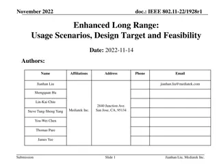
January 2024 DCN 15-24-0036-00-0000 Project: IEEE P802.15 Working Group for Wireless Personal Area Networks (WPANs) Submission Title: Indoor Positioning using OCC and LiDAR Date Submitted: January 14, 2024 Source: Ida Bagus Krishna Yoga Utama, Nguyen Ngoc Huy, Yeong Min Jang [Kookmin University] Address: Kookmin University, 77 Jeongneung-Ro, Seongbuk-Gu, Seoul, 02707, Republic of Korea Voice: +82-2-910-5068 E-Mail: yjang@kookmin.ac.kr Re: Abstract: Present the use case of OCC for indoor positioning Purpose: Presentation for contribution on IEEE 802.15 IG NG-OCC Notice: This document has been prepared to assist the IG NG-OCC. It is offered as a basis for discussion and is not binding on the contributing individual(s) or organization(s). The material in this document is subject to change in form and content after further study. The contributor(s) reserve(s) the right to add, amend or withdraw material contained herein. Release: The contributor acknowledges and accepts that this contribution becomes the property of IEEE and may be made publicly available by IG NG-OCC. Slide 1 Yeong Min Jang Submission
January 2024 DCN 15-24-0036-00-0000 Indoor Positioning using OCC and LiDAR January 14, 2024 Slide 2 Yeong Min Jang Submission
January 2024 DCN 15-24-0036-00-0000 Contents Background Methodology Experiment Results Conclusion Slide 3 Yeong Min Jang Submission
January 2024 DCN 15-24-0036-00-0000 Background Location-based services have become important in recent years. The location information is important to provide easier navigation for the movement of people and autonomous systems. In outdoor environments, positioning is mostly taken care of by utilizing GPS systems. However, in an indoor environment, the GPS is not available. To provide indoor localization, the VLC can be integrated with the sensor fusion of camera-LiDAR. The integration can be extended by employing UWB and WiFi fingerprints. Slide 4 Yeong Min Jang Submission
January 2024 DCN 15-24-0036-00-0000 Background There are two categories in which VLC can be used for indoor positioning: VLC as the main technology 1. VLC as the supporting technology Slide 5 Yeong Min Jang Submission
VLC AS THE MAIN TECHNOLOGY Slide 6 Yeong Min Jang 6 Submission
January 2024 DCN 15-24-0036-00-0000 Methodology To this day, VLC-based indoor localization is only performed in 2-D or with a fixed ceiling height. Employing LiDAR and IMU sensors can help establish 3-D indoor positioning. The LIDAR provides a real-time ceiling height estimation to generate the location in 3-D space. The VLC will provide 2-D positioning with centimeter-scale accuracy. The IMU sensor helps improve the VLC performance by estimating the angle of attack of the VLC rays relative to the camera reception. The main goal is to establish a truly 3D visible light positioning (VLP) system based on a single LED transmitter. Slide 7 Yeong Min Jang Submission
January 2024 DCN 15-24-0036-00-0000 Methodology How does it work? The VLC system utilizes angle-of- arrival (AOA) position information. The AOA information is decoded from the captured high-frame rate video, while the tilt angle from the gravity sensor is used to make corrections to the estimated AOA information. Height measurements LiDAR and AOA information are used to estimate the locations in a 3-D space. The rolling shutter effect is utilized to decode the transmitted signal. to determine from <Estimating position based on AOA and ceiling height information> Slide 8 Yeong Min Jang Submission
January 2024 DCN 15-24-0036-00-0000 Methodology <Overall scenario for indoor localization with VLC as the main technology> Data from the three sensors is timestamped and synchronized for estimating the location. The location is estimated with respect to the transmitter, and the transmitter s location with respect to the global coordinate system is known. The VLC is using a low-resolution, high-fps camera to capture the image, and computer vision techniques are used for estimating the AOA. The AOA, tilt angle, and measured height information are fused to calculate the position in 3-D space. Slide 9 Yeong Min Jang Submission
January 2024 DCN 15-24-0036-00-0000 Methodology When the device is lying flat, the AOA for point P can be expressed as: When the condition is not stationary, the AOA can be calculated by finding the tilt-compensated angle that can be calculated from the gravity sensor. <Principle of AOA estimation> Slide10 Yeong Min Jang Submission
January 2024 DCN 15-24-0036-00-0000 Methodology Then, the second AOA point can be calculated using the following equation: From the aforementioned calculation, the location in spherical coordinates (r, , ) can be retrieved. Conversion to Cartesian coordinates can be done using the following equation: <Principle of AOA estimation> Slide 11 Yeong Min Jang Submission
January 2024 DCN 15-24-0036-00-0000 Experiment The experiment is performed in an indoor environment using the following devices and settings: 1. OCC transmitter: 10W and 5W LED 2. OCC receiver: Galaxy S9 3. LiDAR: Benewake TFmini-S 4. OCC frame 128x72 5. OCC frame rate: 960 fps 6. Packet size: 10-bit 7. Modulation: OOK Samsung resolution: <Experiment setup> Slide12 Yeong Min Jang Submission
January 2024 DCN 15-24-0036-00-0000 Results The experiment is performed in a room measuring 2.5 m x 1.5 m x 3 m using a single LED. The maximum errors towards the X, Y, and Z directions are 9.8 cm, 8.47 cm, and 6 cm, respectively. The average errors towards the X, Y, and Z directions are 5.3 cm, 5.6 cm, and 0.9 cm, respectively. The average positioning error in 3D space is 6.8 cm. <Experiment results and errors> Slide13 Yeong Min Jang Submission
January 2024 DCN 15-24-0036-00-0000 Results The experiment is performed in a room measuring 2.5 m x 1 m x 2 m using two LEDs. The experiment is conducted twice: with static readings and with the user walking on a straight-line path. The cumulative distribution function (CDF) of the positioning errors with 80% error values in the X and Y directions is under 7 cm and 4.5 cm, respectively. The average error in the Z direction is below 1 cm due to the use of LiDAR. The straight walking path has average errors of 4 cm and maximum errors of 10 cm. <Experiment results and errors> Slide14 Yeong Min Jang Submission
VLC AS THE SUPPORTING TECHNOLOGY Slide15 Yeong Min Jang 15 Submission
January 2024 DCN 15-24-0036-00-0000 Methodology In SLAM systems, multiple technologies can be employed together to generate the most accurate performance for indoor positioning. One example is in the CrowdFusion system [2], where the VLC is utilized to perform close-loop detection, which is important in SLAM systems. The LiDAR and other sensor information are combined to establish the SLAM. To refine the SLAM performance, close-loop detection is employed to smoothen the initial traces produced by the SLAM. Slide16 Yeong Min Jang Submission
January 2024 DCN 15-24-0036-00-0000 Methodology <CrowdFusion System> CrowdFusion SLAM combines several technologies. The CrowdFusion SLAM uses visible light and magnetic fields for a two-step trace merging algorithm. After merging the traces, the system builds a radio map with visible light and WiFi signals for sensor fusion positioning based on an improved particle filter. Slide17 Yeong Min Jang Submission
January 2024 DCN 15-24-0036-00-0000 Methodology To perform loop closure detection using visible light, a sequential pose matching algorithm is utilized. The method works by comparing the similarity of visible light RSS to a sequence of poses. The matching pose is defined by the similarity of the visible light RSS between two traces. If the matching pose is lower than the threshold, then it is determined that the pose is matched. Slide18 Yeong Min Jang Submission
January 2024 DCN 15-24-0036-00-0000 Methodology Loop closure detection is usually based on individual pose matching. Due to the noisy visible light, the individual pose-matching approach is prone to a large number of false positive matches. To reduce the false positive matches, a pair of matching segments is defined as the segments with more than three sequential matching poses. The sequential matching poses in a pair of matching segments are searched using a two-round algorithm. The two-round algorithm selects the poses in the same direction and opposite directions. Further validation is performed to further remove false positive matching segments: 1. Best matching poses 2. Consistency of trace shape 3. Consistency of the RSSI vector Slide19 Yeong Min Jang Submission
January 2024 DCN 15-24-0036-00-0000 Experiment The performed in a room with an area of 600 ?2. 16 LEDs are installed in the room, and each LED has 10W of power. The LEDs are driven at six frequencies: 714, 909, 1250, 1428, 1666, and 2500 Hz. experiment is <Experiment room layout> different <LED setup> Slide20 Yeong Min Jang Submission
January 2024 DCN 15-24-0036-00-0000 Results By utilizing the proposed loop closure method, it helps improve the loop closure detection performance. The high loop closure precision helps improve the trace merging accuracy. <Loop closure detection performance> <Loop closure detection performance with different parameters> Slide21 Yeong Min Jang Submission
January 2024 DCN 15-24-0036-00-0000 Results Good loop closure performance leads to better indoor positioning accuracy for the SLAM algorithm. The presence of visible light for indoor positioning highly improved the positioning accuracy compared to other information, such as WiFi. <Positioning accuracy> <Positioning without floor plan> <Positioning with floor plan> Slide22 Yeong Min Jang Submission
January 2024 DCN 15-24-0036-00-0000 Conclusion Two types of VLC usage for indoor positioning are presented. A 3-D visible light positioning system using a very low-resolution high-fps LiDAR has been proposed. The low resolution and high fps are effective in achieving centimeter-scale positioning accuracy. By equipping a LiDAR sensor, the height ambiguity is solved and an accurate Z direction estimation is achieved. The use of tilt angle from the IMU sensor improves the robustness of AOA estimation. Additionally, the combination of AOA with LiDAR measurement is able to produce an accurate indoor positioning system. The VLC can be used to perform loop closure detection in an indoor positioning system. The VLC-based loop closure is proven to significantly improve positioning accuracy in indoor environments. Slide23 Yeong Min Jang Submission
January 2024 DCN 15-24-0036-00-0000 Reference 1. K. Bera, R. Parthiban, and N. Karmakar, A Truly 3D Visible Light Positioning System Using Low Resolution High Speed Camera, LIDAR, and IMU Sensors, IEEE Access, vol. 11, pp. 10.1109/access.2023.3312293. Z. Li, X. Zhao, Z. Zhao, and T. Braun, CrowdFusion: Multisignal Fusion SLAM Positioning Leveraging Visible Light, IEEE Internet of Things Journal, vol. 10, no. 14, pp. 13065 13076, Jul. 2023, doi: 10.1109/jiot.2023.3260205. 98578 98585, 2023, doi: 2. Slide24 Yeong Min Jang Submission