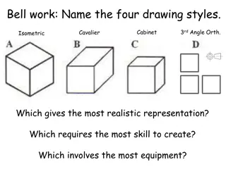
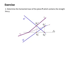
Understanding Orthographic Projections for TV Line Inclined to HP and VP
This detailed content explains how to visualize and project an inclined line in Orthographic Projections, focusing on both Horizontal Plane (HP) and Vertical Plane (VP). It covers procedures for determining True Length, locating objects, and understanding key parameters such as angles and distances. The content also includes a problem-solving example for practical application.

Download Presentation

Please find below an Image/Link to download the presentation.
The content on the website is provided AS IS for your information and personal use only. It may not be sold, licensed, or shared on other websites without obtaining consent from the author. Download presentation by click this link. If you encounter any issues during the download, it is possible that the publisher has removed the file from their server.
E N D
Presentation Transcript
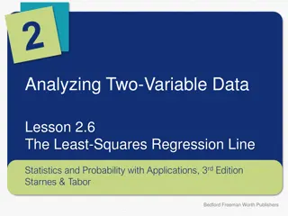
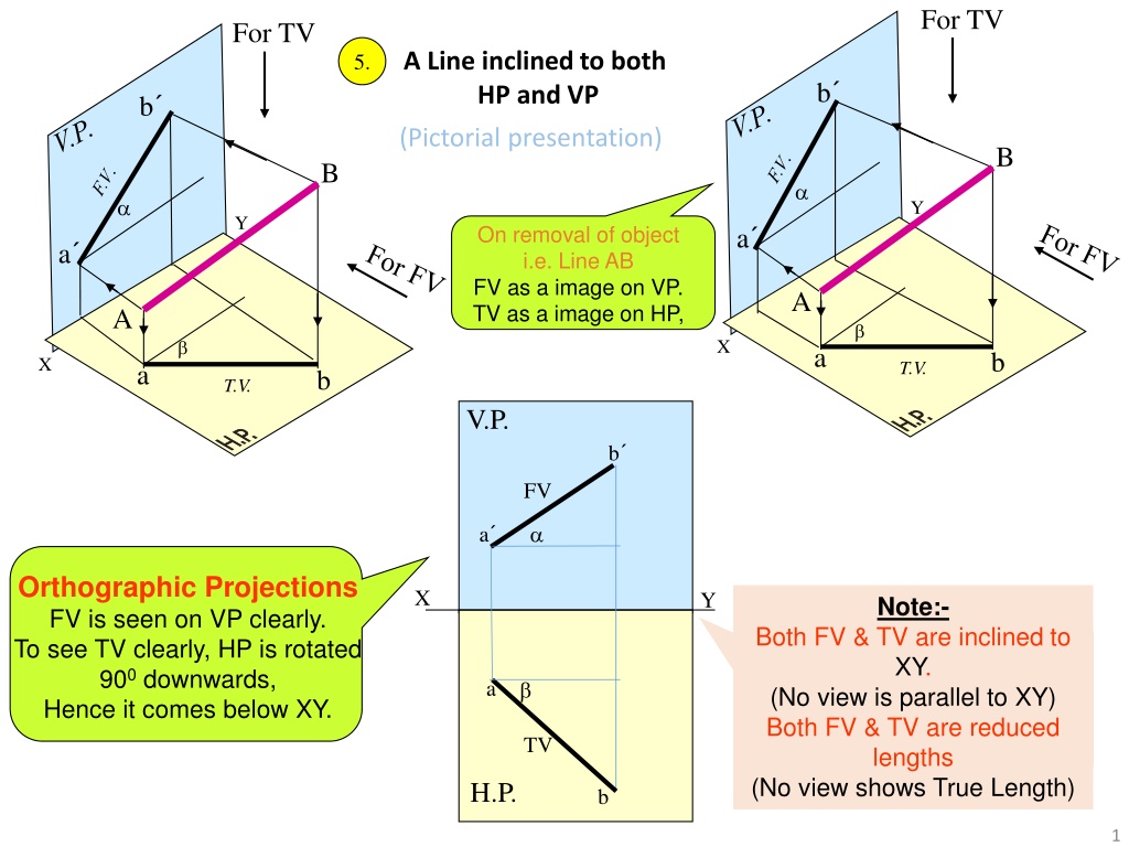
For TV For TV A Line inclined to both HP and VP (Pictorial presentation) 5. b b B B Y Y a On removal of object i.e. Line AB FV as a image on VP. TV as a image on HP, a A A X a b X T.V. a b T.V. V.P. b FV a Orthographic Projections FV is seen on VP clearly. To see TV clearly, HP is rotated 900 downwards, Hence it comes below XY. X Y Note:- Both FV & TV are inclined to XY. (No view is parallel to XY) Both FV & TV are reduced lengths (No view shows True Length) a TV H.P. b 1
Note the procedure When FV & TV known, How to find True Length. (Views are rotated to determine True Length & it s inclinations with HP & VP). 2 Note the procedure When True Length is known, How to locate FV & TV. (Component a-1 of TL is drawn which is further rotated to determine FV) Orthographic Projections Means FV & TV of Line AB are shown below, with their apparent inclinations & V.P. V.P. V.P. b b1 b1 b b FV FV TL a 1 a a Y X X Y X Y 1 a b2 a a TV TV TV H.P. H.P. b H.P. b b b1 In this sketch, TV is rotated and made // to XY line. Hence it s corresponding FV, a b1 is showing True Length & True Inclination with HP. Here a -1 is component of TL ab1 gives length of FV. Hence it is brought upto Locus of a and further rotated to get point b .a b will be FV. Similarly drawing component of other TL (a b1 ) TV can be drawn. Here TV (ab) is not // to XY line Hence it s corresponding FV a b is not showing True Length & True Inclination with HP.
1) True Length (TL) a b1 & a b1 2) Angle of TL with HP - 3) Angle of TL with VP 4) Angle of FV with XY 5) Angle of TV with XY 6) LTV (length of FV) Component (a-1) 7) LFV (length of TV) Component (a -1 ) 8) Position of A- Distances of a & a from XY 9) Position of B- Distances of b & b from XY 10) Distance between End Projectors Diagram showing graphical relations among all important parameters of this topic. TEN important parameters to be remembered with notations used here onward V.P. Distance between End Projectors. b b1 1 a LTV NOTE & b & b1 on same locus. Construct with a X Y LFV a & 1 Construct with a b & b1 on same locus. Also remember b1 b True Length is never rotated. It s horizontal component is drawn & it is further rotated to locate view. H.P. Views are always rotated, made horizontal & further extended to locate TL, & 3
INCLINED TO HP & VP PROBLEM 7: Line AB is 75 mm long and it is 300 & 400 inclined to HP & VP respectively. End A is 12mm above HP and 10 mm in front of VP. Draw projections. Line is in 1st quadrant. b b 1 Solution steps: 1) Draw XY line and one projector. 2) Locate a 12mm above XY line & a 10mm below XY line. 3) Take 300 angle from a & 400 from a and mark TL, i.e., 75mm on both lines. Name those points respectively. 4) Draw horizontal component of TL a b1 from point b1 and name it 1. (the length a-1 gives length of FV as we have seen already) 5) Extend it up to locus of a and rotating a as center locate b as shown. Join a b as FV. 6) From b drop a projector downward & get point b. Join a & b, i.e., TV. FV TL a b1 and b X Y LFV a 1 TV TL b b1 4
FINDING INCLINATION WITH HP PROBLEM 8: Line AB 75mm long makes 450inclination with VP while it s FV makes 550. End A is 10 mm above HP and 15 mm in front of VP. If line is in 1stquadrant draw it s projections and find it s inclination with HP. b 1 b Solution Steps:- LOCUS OF b1 1.Draw xy line. 2.Draw one projector for a & a 3.Locate a 10mm above XY & a 15 mm below XY. 4.Draw a line 450 inclined to XY from point a and cut TL 75 mm on it and name that point b1. 5.Draw locus from point b1. 6.Take 550 angle from a for FV above XY line. 7.Draw a vertical line from b1 up to locus of a and name it 1. It is horizontal component of TL & is LFV. 8.Continue it to locus of a and rotate upward up to the line of FV and name it b . This a b line is FV. 9. Drop a projector from b on locus from point b1 and name intersecting point b. Line ab is TV of line ab. 10.Draw locus from b and with TL distance cut point b1 11.Join a b1 as TL and measure it s angle at a . It will be true angle of line with HP. 550 a Y X LFV a 1 LOCUS OF b1 b b1 5
FINDING TL AND INCLINATIONS PROBLEM 9: FV of line AB is 500 inclined to XYand measures 55 mm long while it s TV is 600 inclined to XYline. If end A is 10 mm above HP and 15 mm in front of VP, draw it s projections, find TL, inclinations of line with HP & VP. b 1 b Solution steps: 1.Draw XY line and one projector. 2.Locate a 10 mm above XY and a 15 mm below XY line. 3.Draw locus from these points. 4.Draw FV 500from a and mark b cutting 55mm on it. 5.Similarly draw TV 600 from a & drawing projector from b locate point b and join a b. 6.Then rotating views as shown, locate True Lengths ab1 & a b1 and their angles with HP and VP. 500 a Y X a 600 b1 b 6
FINDING ANGLE WITH HP & VP PROBLEM 10:- Line AB is 75 mm long. It s FV and TV measure 50 mm & 60 mm long respectively. An end is 10 mm above HP and 15 mm in front of VP. Draw projections of line AB if end B is in first quadrant. Find angle with HP and VP. b 1 b SOLUTION STEPS: 1.Draw XY line and one projector. 2.Locate a 10 mm above XY and a 15 mm below XY line. 3.Draw locus from these points. 4.Cut 60mm distance on locus of a & mark 1 on it as it is LTV. 5.Similarly cut 50mm on locus of a and mark point 1 as it is LFV. 6.From 1 draw a vertical line upward and from a taking TL (75mm ) in compass, mark b 1 point on it. Join a b 1 points. 7. Draw locus from b 1 8. With same steps below get b1 point and draw also locus from it. 9. Now rotating one of the components i.e., a-1 locate b and join a with it to get FV. 10. Locate TV similarly and measure angles and 1 LTV a X Y LFV a 1 b1 b 7
FINDING ANGLE WITH HP & VP PROBLEM 11:-TV of a 75 mm long line CD, measures 50 mm. End C is in HP and 50 mm in front of VP. End D is 15 mm in front of VP and it is above HP. Draw projections of CD and find angles with HP and VP. LOCUS OFd d 1 SOLUTION STEPS: d 1.Draw XY line and one projector. 2.Locate c on XY and c 50mm below XY line. 3.Draw locus from these points. 4.Draw locus of d 15 mm below XY. 5.Cut 50mm & 75 mm distances on locus of d from c and mark points d & d1 as these are TV and TL. Join both with c. 6.From d1 draw a vertical line upward up to XY i.e., up to locus of c and draw an arc as shown. 7 Then draw one projector from d to meet this arc in d point & join c d 8. Draw locus of d and cut 75 mm on it from c as TL 9.Measure angles and c Y X d1 LOCUS OFd d c 8
FINDING TRUE ANGLE PROBLEM 9:-Two straight lines PQ and QR make an angle of 120 between them in front and top views. PQ is 60 mm long and is parallel to and 15 mm from both H.P. and V.P. Determine the true angle between PQ and QR, if point R is 50 mm above H.P. (EXAMPLE) R SOLUTION STEPS: 1. Draw a reference line xy. Mark point p at 15 mm above xy and point p at 15 mm below xy. 2. Draw 60 mm long lines p q and pq, parallel to xy. 3. Draw a line from point q , inclined at 120 to xy such that it meets the horizontal line at 50 mm above xy at point r . Join q r and p r . 4. Draw a line from point q, inclined at 120 to xy such that it meets the projector from r at a point r. Join qr and pr. 5. As lines pq and p q are parallel to xy, they represent the true length of side PQ. Here PQ = 60 mm. 6. Draw an arc with centre p and radius pr to meet the horizontal line from p at point r1. Project point r1 to meet horizontal lines from point r at point r1 . Join p r1 to represent the TL of the line PR. Here, PR = p r1 = 94 mm. r r1 r 2 50 P Q p q 15 60 X 15 Y q p r1 r2 7. Draw an arc with centre q and radius qr, to meet the horizontal line at r2. Project point r2 to meet horizontal lines form point r at point r 2. Join q r2 to represent the TL of line QR. Here, QR = q r2 = 53mm. r 8. Draw actual triangle PQR taking true lengths, i.e., 60 mm, 94 mm and 53 mm. Measure the inclined angle PQR as the actual angle between sides PQ and QR. Here, it is 112 . 9
PROBLEMS INVOLVING TRACES OF THE LINE TRACES OF THE LINE:- These are the points of intersections of a line ( or it s extension ) with respect to reference planes. A line itself or its extension, where ever touches H.P., that point is called TRACE OF THE LINE ON H.P. (It is called H.T.) Similarly, a line itself or it s extension, where ever touches V.P., that point is called TRACE OF THE LINE ON V.P. (it is called V.T.) V.T.:- It is a point on VP. Hence it is called FV of a point in VP. Hence it s TVcomes on XY line.( Here onward denoted as v ) H.T.:- It is a point on HP. Hence it is called TV of a point in HP. Hence it s FV comes on XY line.( Here onward denoted as h ) 10
b STEPS TO LOCATE HT (WHEN PROJECTIONS ARE GIVEN) 1. 2. 3. 4. Begin with FV. Extend FV up to XY line. Name this point h (as it is a FV of a point in HP) Draw one projector from h . Now extend TV to meet this projector. This point is HT a v h Y x HT VT a STEPS TO LOCATE VT (WHEN PROJECTIONS ARE GIVEN) Observe & note :- 1. Points h & v always on x-y line. b 1. 2. 3. 4. Begin with TV. Extend TV up to XY line. Name this point v (as it is a TV of a point in VP) Draw one projector from v. Now extend FV to meet this projector. This point is VT 2. VT & v always on one projector. 3. HT & h always on one projector. 4. FV - h - VT always co-linear. 5. TV - v - HT always co-linear. These points are used to solve next three problems. 11
VARIOUS ORIENTATIONS OF THE STRAIGHT LINES VARIOUS ORIENTATIONS OF THE STRAIGHT LINES Orientation/ Position of line Elevation 12 Sl. No. Front view/ Top view/ plan Horizontal trace Vertical trace 1 Line parallel to both HP and VP True length, parallel to xy True length, parallel to xy Does not exist Does not exist 2 Line perpendicular to HP True length, perpendicular to xy Point Coincides with top view Does not exist 3 Line perpendicular to VP Point True length, perpendicular to xy Does not exist Coincides with front view 4 Line inclined at to HP and parallel to VP True length inclined at to xy Shorter than the true length, parallel to xy Exists Does not exist 5 Line inclined at to VP and parallel to HP Shorter than the true length, parallel to xy True length inclined at to xy Does not exist Exists 6 Line situated in HP and inclined at to VP Shorter than the true length, lying on xy True length inclined at to xy Does not exist Exists on xy 7 Line situated in VP and inclined at True length inclined at to xy Shorter than the true length, lying on xy Exists on xy Does not exist 8 Line situated both in HP and VP Both front and top views are true length and coincide on xy Does not exist Does not exist
FINDING INCLINATION WITH HP & VP PROBLEM 12 :- FV of line AB makes 450 angle with XY line and measures 60 mm. Line s TV makes 300with XY line. End A is 15 mm above HP and it s VT is 10 mm below HP. Draw projections of line AB, determine inclinations with HP & VP and locate HT, VT. b 1 b SOLUTION STEPS:- 1. Draw XY line, one projector and locate FV (a ) 15 mm above XY. 2. Take 450 angle from a and marking 60 mm on it locate point b . 3. Draw locus of VT, 10 mm below XY & extending FV to this locus locate VT, as FV-h -VT lie on one straight line. 4. Draw projector from VT , locate V on XY. 5. From V take 300 angle downward as TV and it s inclination can begin with v. We get point a. 6. Draw projector from b and locate b, i.e., TV point. 7. Draw a projector from h below it, locate HT. 8. Draw locus of a, b, b 9. With ab as radius draw an arc to locus of a and extend it upto b 1. Join a b 1. We get 10. Similarly find with a b as radius. a 450 15 v x Y h 300 10 VT a b b1 13
FINDING TL WITH ITS INCLINATION WITH HP & VP PROBLEM 13 : One end of line AB is 10mm above HP and other end is 100 mm in-front of VP. It s FV is 450 inclined to XYwhile it s HT & VT are 45mm and 30 mm below XY respectively. Draw projections and find TL with it s inclinations with HP & VP. b b 1 LOCUS OF b & b 1 SOLUTION STEPS:- 1. Draw XY line, one projector and locate a 10 mm above XY. 2. Draw locus 100 mm below XY for points b & b1 3. Draw loci for VT and HT, 30 mm & 45 mm below XY respectively. 4. Take 450 angle from a and extend that line backward to locate h and VT. Locate v on XY above VT. Locate HT below h as shown. 5. Then join v HT and extend to get top view end b. 6.Draw projector upward and locate b . Make ab & a b dark. 7. Now as usual rotating views find TL and it s inclinations. 450 a 10 v h Y X 30 45 VT HT 100 a LOCUS OF b & b1 b1 b 14
LOCATING TRACES, FINDING TL AND INCLINATIONS PROBLEM 14:-Projectors drawn from HT and VT of a line AB are 80 mm apart and those drawn from it s ends are 50 mm apart. End A is 10 mm above HP, VT is 35 mm below HP while it s HT is 45 mm in front of VP. Draw projections, locate traces and find TL of line & inclinations with HP and VP. VT SOLUTION STEPS:- b b 1 1.Draw XY line and two projectors, 80 mm apart and locate HT & VT, 35 mm below XY and 55 mm above XY respectively on these projectors. 2.Locate h and v on XY as usual. 3.Now just like previous two problems, extending certain lines complete FV & TV, and as usual find TL and it s inclinations. 55 a Locus of a 10 50 v Y X h b 1 b 35 a HT 80 15
Instead of considering a & a as projections of first point, if V & VT are considered as first point , then true inclinations of line with HP & VP i.e. angles & can be constructed with points VT & V respectively. b b1 Then from point v & HT angles can be drawn. & From point VT & h angles can be drawn. & a & V h X Y VT HT THIS CONCEPT IS USED TO SOLVE NEXT THREE PROBLEMS. a 16 b1 b


 True Length (TL) –a’ b1’ & a b1")