Understanding Drawing Styles in Engineering

Explore the different drawing styles used in engineering, including Cabinet, 3rd Angle Orthographic, Cavalier, and Isometric projections. Learn about the benefits and limitations, key features, and applications of each style. Gain insights into the skill levels required, equipment needed, and practical uses for engineers. Discover how these styles impact speed of production, visual impact, and accuracy in representing engineering components.

Download Presentation

Please find below an Image/Link to download the presentation.
The content on the website is provided AS IS for your information and personal use only. It may not be sold, licensed, or shared on other websites without obtaining consent from the author. Download presentation by click this link. If you encounter any issues during the download, it is possible that the publisher has removed the file from their server.
E N D
Presentation Transcript
Bell work: Name the four drawing styles. Cabinet 3rd Angle Orth. Cavalier Isometric Which gives the most realistic representation? Which requires the most skill to create? Which involves the most equipment?
Write this down: Learning outcomes. P2: To be able to describe the benefits and limitations of using pictorial techniques to represent a given engineering component.
Benefits and limitations of different drawing styles. Things to consider; 1. speed of production, 2. visual impact, 3. limitations eg lengths and shapes not true, 4. not produced to a recognised standard, 5. dimensions difficult to read, 6. consequences of interpretation errors e.g. incorrect manufacture, incorrect assembly, cost to scrap. 7. possible applications for engineers.
Which drawing styles is represented in the picture below? Describe the key features of isometric. Write this down: 30 /60 lines. Perpendicular lines. 3 dimensional. Measurements to scale (sides in proportion to the products real size.)
Write all this down: Isometric - Benefits When used as an exploded diagram can realistically indicate where parts fit together. Provides an overall 3D view of a product. Used by product designers and engineers from a variety of sectors to convey a realistic image. Also good for consumers to present a 3D image of a product.
Write all this down: Isometric - Limitations No dimensions as the 3D view would make them difficult to interpret, although should be sketched to scale. Requires high skill levels to produce readable drawings. Rear of the object cannot be viewed, which may mean important information is not visible.
Which drawing styles is represented in the pictures below? Describe the key features of cabinet and cavalier projections. Write this down: Sometimes called oblique projections. Front view drawn in 2D. 3D sketches presented at 45 . Cavalier represents depth at 1:1 scale. Cabinet represents depth at 1:2 scale.
Cabinet and Cavalier projections - Benefits Write all this down: Very easy to draw with very little training. 45 angles are easily estimated by novices. Presents a clear front view of an object with an element of 3D appearance. Requires no specialist equipment.
Cabinet and Cavalier projections - Limitations Write all this down: Can look less realistic drawing styles such as isometric and 2 point perspective as the side a top view of the object can appear unconvincing in shape. Can be difficult to dimension and ratio can have the appearance of being incorrect. You cannot view the back of the product. Is a 2 dimensional image of a product with forced depth professionals consider the technique crude.
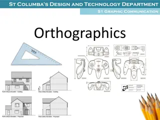
Which drawing styles is represented in the pictures below? Describe the key features of 1st and 3rd Angle Orthographic Projections. Write this down: Plan, side and front views of a product. Draw evenly spaced on a page and in line. All details and measurements included. Drawn to a given scale with an information block the provides details to the drawing to the reader.
3rd and 1st Angle Orthographic Projections - Benefits Write all this down: Used by engineers, especially those who are dealing with machining components and parts. Follow the universal standards followed by all engineers. All information clearly laid out, no repetition of dimensions. Technical information given a defined space. All sides clearly depicted in high levels of detail. Can be used as a guide from which other styles of drawing can be created. Easy to identify flaws or faults as all possible views and details are included.
3rd and 1st Angle Orthographic Projections - Limitations Write all this down: 2D limits the realism of the drawing therefore it takes time and effort to interpret fully. Untrained readers may struggle to visual the object from in 3D. Specialist knowledge of mathematical symbols and the use of engineering standards (such as centre lines and hidden feature details) will be required. Specialist equipment is also required, templates, set squares, drawing boards, compasses etc. People new to engineering or industrial time will require specialist training and lots of time to be able to produce the drawing effectively. Consumers may not understand the drawing fully, which may affect their decisions to purchase the product depicted.
Write the Learning Outcomes here: Description of style Advantages Disadvantages 3rd and 1st Angle Orthographic Projection
Description of style Advantages Disadvantages Isometric Cabinet/cavalier
Bell work: Name the four drawing styles. Which gives the most realistic representation? Which requires the most skill to create? Which involves the most equipment?
Which drawing styles is represented in the pictures below? What are the key features of this drawing style?
Which drawing styles is represented in the pictures below? What are the key features of this drawing style?
Which drawing styles is represented in the pictures below? What are the key features of this drawing style?
Learning outcomes. P2: To be able to describe the benefits and limitations of using pictorial techniques to represent a given engineering component. Your must produce a report on the three types of drawings you mastered in P1. For each style you should write one paragraph to introduce each drawing, one paragraph on its benefits and one on its limitations. Your report should compare/contrast and evaluate the styles against each other.