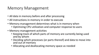
Understanding Caches and the Memory Hierarchy in Computer Systems
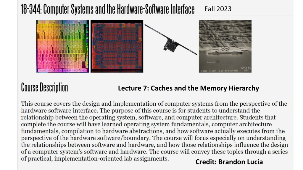
Delve into the intricacies of memory hierarchy and caches in computer systems, exploring concepts like cache organization, implementation choices, hardware optimizations, and software-managed caches. Discover the significance of memory distance from the CPU, the impact on hardware/software interfaces, and the optimization strategies for data movement. Explore the memory hierarchy from registers to main memory, emphasizing the trade-offs between speed, size, and cost at each level.

Download Presentation

Please find below an Image/Link to download the presentation.
The content on the website is provided AS IS for your information and personal use only. It may not be sold, licensed, or shared on other websites without obtaining consent from the author. Download presentation by click this link. If you encounter any issues during the download, it is possible that the publisher has removed the file from their server.
E N D
Presentation Transcript
Fall2023 Lecture 7: Caches and the Memory Hierarchy Credit: Brandon Lucia
Today: Caches and the Memory Hierarchy Introduction to caches and cache organization Caches in the memory hierarchy Cache implementation choices Cache hardware optimizations Software-managed caches & scratchpad memories
Memory is a big list of M bytes Byte M . . . lw x6 0xC Byte 0xF Byte 0xE Byte 0xD Byte 0xC Register Write-Back Fetch Decode Memory Execute . . . Byte 2 Byte 1 Byte 0
Memory is conceptually far away from CPU Byte M lw x6 0xC Mem/Mem Fwd Mem/Mem Fwd WB/Mem Fwd WB/Mem Fwd Addr Reg A Data Reg B . . . MUX MUX MUX What does this distance entail for a hardware / software interface? Byte 0xF Byte 0xE Byte 0xD Byte 0xC Read Data C Memory Unit Cont. Sigs.: Op. Select [Ld/St] . . . Memory Byte 2 Byte 1 Byte 0
Memory is conceptually far away from CPU Byte M lw x6 0xC Mem/Mem Fwd Mem/Mem Fwd WB/Mem Fwd WB/Mem Fwd What does this distance entail for a hardware / software interface? Need to be judicious with lw & sw Compiler & programmer must carefully lay out memory Worth spending hardware resources to optimize Need hardware and software to co-optimize data re-use Data movement is a fundamental limit on speed & energy Addr Reg A Data Reg B . . . MUX MUX MUX Byte 0xF Byte 0xE Byte 0xD Byte 0xC Read Data C Memory Unit Cont. Sigs.: Op. Select [Ld/St] . . . Memory Byte 2 Byte 1 Byte 0
Memory hierarchy: large & slow vs. small & fast Byte M lw x6 0xC L L1 1I I$ $ Byte I1 Mem/Mem Fwd Mem/Mem Fwd WB/Mem Fwd WB/Mem Fwd L3$ Addr Reg A Data Reg B Byte M3 . . . L2$ MUX MUX MUX Byte M2 Byte 0xF Byte 0xE Byte 0xD Byte 0xC Read Data C Memory Unit Cont. Sigs.: Op. Select [Ld/St] L1D$ Byte M1 . . . Memory Byte 2 Byte 1 Capacity inversely proportional to access cost M > M3 > M2 > M1 Byte 0
Recall: Memory Hierarchy from 18x13 L0: Regs CPU registers hold words retrieved from the L1 cache. Smaller, faster, and costlier (per byte) storage devices L1 cache (SRAM) L1: L1 cache holds cache lines retrieved from the L2 cache. L2 cache (SRAM) L2: L2 cache holds cache lines retrieved from L3 cache. L3 cache (SRAM) L3: L3 cache holds cache lines retrieved from main memory. Larger, slower, and cheaper (per byte) storage devices L4: Main memory (DRAM) Main memory holds disk blocks retrieved from local disks. Local secondary storage (SSD/Disk) L5: Local disks hold files retrieved from disks on remote servers. Remote secondary storage (e.g., Web servers) L6:
Recall from 18x13: The Working Set The data that is presently being use is called the Working Set. Imagine you are working on 18x13. Your working set might include: The lab handout A terminal window for editing A terminal window for debugging A browser window for looking up man pages If you changed tasks, you d probably hide those windows and open new ones The data computer programs use works the same way.
Recall from 18x13: Guesstimating the Working Set How does the memory system (cache logic) know the working set? This is tricky. There is no way it can really know what data the program needs or will need soon. It could even be totally dynamic, based upon input. It approximates it using a simple heuristic called locality: Temporal locality: Data used recently is likely to be used again in the near future (local in time). Spatial locality: Data near the data used recently is likely to be used soon (local in space, e.g. address space). The memory system will bring and keep the Most Recently Used (MRU) data and data near it in memory to the higher layers while evicting the Least Recently Used (LRU) data to the lower layers.
Whats New Since 18x13? We want to think about a cache built natively in real hardware vs a software simulation of a cache The 18x13 cache was a software simulation of a somewhat ideal LRU cache Consider how you built an LRU cache simulator in 18x13: A linked list- based queue? A copy-to-shift array-based queue? Time for the 18-240 Thinking Cap : Consider the implementation of LRU in hardware Can the 18x13 approach be translated to real hardware in a practical way?
Locality is the key to cache performance Spatial Locality Temporal Locality Why do we see locality? What are some examples of each?
Memory hierarchy: Unified vs. Split ICache & DCache Byte M lw x6 0xC L L1 1I I$ $ Byte I1 Mem/Mem Fwd Mem/Mem Fwd WB/Mem Fwd WB/Mem Fwd L3$ Addr Reg A Data Reg B Byte M3 . . . L2$ MUX MUX MUX Byte M2 Byte 0xF Byte 0xE Byte 0xD Byte 0xC Read Data C Memory Unit Cont. Sigs.: Op. Select [Ld/St] L1D$ Byte M1 . . . Memory Byte 2 Byte 1 L1 Instruction & L1 Data cache often separate (why?) Lower levels of cache are unified (why?) Byte 0
Review: Anatomy of a set-associative cache Way 0 Way 1 Way 2 Way 3 Typical Parameters Line contains 16-64 bytes of data 1-8 number of sets 1 set contains all lines? All sets contain 1 line? Total size varies by level: L1: 1kB 32kB L3: a few kB 48MB L3$ Set 0 Line Set 1 B bytes data Valid Dirty Tag Set 2 Anatomy of a Line Set 3
Review: Accessing the cache Way 0 Way 1 Way 2 Way 3 L3$ Step 1: Partitioning the address Set 0 Line lb x6 0x7fff0053 set index Set 1 0x01111111111111110000000001010011 tag bits block offset Set 2 32 bytes data Valid Dirty Tag Set 3 Total cache size = 32B x 4 sets x 4 ways = 512B
Review: Accessing the cache lb x6 0x7fff0053 Way 0 Way 1 Way 2 Way 3 L3$ Step 2: Select the set Set 0 Line set index Set 1 0x01111111111111110000000001010011 tag bits block offset Set 2 set 2 Set 3
Review: Accessing the cache - Hit lb x6 0x7fff0053 Way 2 Way 0 Way 1 Way 3 L3$ L3$ Step 3: Check valid, compare tags Set 0 Line Tag match, valid Set 1 set index 0x01111111111111110000000001010011 tag bits block offset Set 2 1,1,0x001e00, 1,1,0x7fff00, 1,0,0x7fff10, 1,0,0x000000, Set 3 32 bytes data Valid Dirty Tag
Review: Accessing the cache - Hit lb x6 0x7fff0053 Step 4: Fetch cache block for memory unit via cache controller 0x01111111111111110000000001010011 Way 2 Way 0 Way 1 Way 3 block offset = byte 19 L L3 3$ $ Set 0 Line WB/Mem Fwd WB/Mem Fwd Addr Reg A Data Reg B lb Set 1 MUX MUX MUX Cache Controller Read Data C Memory Unit Cont. Sigs.: Op. Select [Ld/St] Set 2 1,1,0x001e00, 1,1,0x7fff00, 1,0,0x7fff10, 1,0,0x000000, Single Byte of Data @ 0x7fff0053 Set 3 Memory
Review: Accessing the cache - Miss lb x6 0x7fff0053 Way 2 Way 0 Way 1 Way 3 L3$ L3$ Step 3: Check valid, compare tags Set 0 Line No tag match, or invalid Set 1 set index 0x01111111111111110000000001010011 tag bits block offset Set 2 1,1,0x001e00, 0,1,0x7fff00, 1,0,0x7fff10, 1,0,0x000000, Set 3 32 bytes data Valid Dirty Tag
Review: Accessing the cache - Miss lb x6 0x7fff0053 Byte M 0011 Way 2 Way 0 Way 1 Way 3 fset 9 L3$ Set 0 Line . . . @ 0x7fff0000 32 Byte Block Set 1 ache ontroller Set 2 . . . 1,1,0x001e00, 1,0,0x7fff00, 1,0,0x7fff10, 1,0,0x000000, Byte 2 Set 3 Byte 1 Byte 0
Review: Accessing the cache - Miss lb x6 0x7fff0053 Step 5: Fetch cache block for memory unit via cache controller 0x01111111111111110000000001010011 Way 2 Way 0 Way 1 Way 3 block offset = byte 19 L L3 3$ $ Set 0 Line WB/Mem Fwd WB/Mem Fwd Addr Reg A Data Reg B lb Set 1 MUX MUX MUX Cache Controller Read Data C Memory Unit Cont. Sigs.: Op. Select [Ld/St] Set 2 1,1,0x001e00, 1,0,0x7fff00, 1,0,0x7fff10, 1,0,0x000000, Single Byte of Data @ 0x7fff0053 Set 3 Memory
Why do we miss in the cache? The 3 C s of misses Compulsory Conflict Capacity
Why miss? Compulsory misses First access to any block of memory is always a miss; these misses are compulsory
Why miss? Capacity misses Working set of program contains more data than can be cached at one time. By the pigeonhole principle caching all data requires missing at least once
Why miss? Conflict misses Multiple blocks of memory map to the same location in the cache and conflict, even if there is still some empty space in the cache L3$
How many bits in tag/index/offset? Way 0 Way 1 Way 2 Way 3 lb x6 0x7fff0053 L3$ set index Set 0 Line 0x01111111111111110000000001010011 tag bits block offset Set 1 Why these numbers of bits? Set 2 32 bytes data Valid Dirty Tag Set 3 Total cache size = 32B x 4 sets x 4 ways = 512B
How many bits in tag/index/offset? Way 0 Way 1 Way 2 Way 3 lb x6 0x7fff0053 L3$ set index Set 0 Line 0x01111111111111110000000001010011 tag bits block offset Enough block offset bits to count block bytes Enough set index bits to count the sets All left-over bits are tag bits Question: what do tag bits mean? Set 1 Set 2 32 bytes data Valid Dirty Tag Set 3 Total cache size = 32B x 4 sets x 4 ways = 512B
How many sets should your cache have? Way 2 Way 0 Way 1 Way 3 L3$ L3$ Set 0 Line #Ways parallel tag matches per lookup Set Associative Cache Design Procedure 1.Select total cache size 2.Select implementable #ways 3.cache size = #sets x #ways x #block_bytes 4.#sets = cache size / (#ways x #block_bytes) Set 1 Set 2 1,1,0x001e00, 0,1,0x7fff00, 1,0,0x7fff10, 1,0,0x000000, What is an implementable # of ways? Set 3
What is an implementable # ways? Way 2 Way 0 Way 1 Way 3 L3$ L3$ Set 0 Line n-way set associative cache: Need n parallel comparators for tag match Set 1 Set 2 1,1,0x001e00, 0,1,0x7fff00, 1,0,0x7fff10, 1,0,0x000000, Set 3
What is an implementable # ways? Fully-associative cache: # comparators = # lines in entire cache L3$ Line 1,1,0x001e00, 0,1,0x7fff00, 1,0,0x7fff10, 1,0,0x000000,
What is an implementable # ways? L3$ Direct mapped cache: 1 comparator because each set contains a single line 1,1,0x001e00, 0,1,0x7fff00, 1,0,0x7fff10, 1,0,0x000000,
Physical implementation separates data & tags set index 0x01111111111111110000000000010011 tag bits Way 0 Way 1 Way 2 Way 3 block offset L3$ Set 0 Line Set 1 Way 2 Way 0 Way 3 Way 1 L3$ Set 0 tag 3 tag 1 tag 2 tag 0 Set 2 Set 1 Set 2 Set 3 Set 3 Cache Tag Array Cache Data Array
Sequential Tag Lookup & Data Lookup set index 0x01111111111111110000000000010011 tag bits Way 2 Way 0 Way 3 Way 1 block offset L3$ 2-bit set select 2-bit set select 4-bit block select Set 0 Line 2-bit way select Set 1 Way 2 Way 0 Way 3 Way 1 L3$ Set 0 tag 3 tag 1 tag 2 tag 0 Set 2 Set 1 Sequentially access tag array first, then access the data array using the result of the tag lookup. Set 2 Set 3 Question: Can you think of an alternative scheme to optimize tag/data lookup? Set 3 Cache Tag Array Cache Data Array
Parallel Tag Lookup & Data Lookup set index 0x01111111111111110000000000010011 tag bits 2-bit way select 2-bit set select Block Select Way 0 Way 3 block offset L3$ Set 0 Line Set 1 Way 2 Way 0 Way 3 Way 1 L3$ Set 0 tag 3 tag 1 tag 2 tag 0 Set 2 Set 1 Fetch all ways in set in parallel with tag matching and use the way index of tag to select the one data block that was fetched. Set 2 Set 3 Question: Pros & cons of parallel lookup? Set 3 Cache Tag Array Cache Data Array
Way Prediction: Cost Like Sequential, Performance Like Parallel Tag Lookup Prediction validator ? set index 0x01111111111111110000000000010011 tag bits Way 2 Way 0 Way 3 Way 1 block offset L3$ way 2-bit set select 2-bit set select predictor 4-bit block select Set 0 Line Set 1 Way 2 Way 0 Way 3 Way 1 2-bit way select L3$ Set 0 tag 3 tag 1 tag 2 tag 0 Set 2 Set 1 Send some tag bits and set index bits to fast way predictor, output of which is 4-bit block select, like in sequential. Fetch way of matched tag and send to prediction validation logic. If correct predict: use block. If incorrect predict: discard block and refetch. Set 2 Set 3 Set 3 Cache Tag Array Cache Data Array
Moritz Lipp, Vedad Hadi, Michael Schwarz, Arthur Perais, Cl mentine Maurice, and Daniel Gruss. 2020. Take A Way: Exploring the Security Implications of AMD's Cache Way Predictors. In Proceedings of the 15th ACM Asia Conference on Computer and Communications Security (ASIA CCS '20). Association for Computing Machinery, New York, NY, USA, 813 825. https://doi.org/10.1145/3320269.3384746
Cost of Associativity 512 Bytes, 256-bit (32B) lines, 1-way 512 Bytes, 256-bit (32B) lines, 4-way $ ./destiny config/SRAM_512_4_256.cfg $ ./destiny config/SRAM_512_1_256.cfg Read Latency = 55.4943ps Tag Read Latency = 277.84ps Write Latency = 54.7831ps Tag Write Latency = 212.575ps Read Latency = 83.4307ps Tag Read Latency = 293.516ps Write Latency = 83.1343ps Tag Write Latency = 226.518ps Read Bandwidth = 674.493GB/s Write Bandwidth = 633.944GB/s Read Bandwidth = 480.942GB/s Write Bandwidth = 500.715GB/s Tag Read Dynamic Energy = 0.281324pJ Tag Write Dynamic Energy = 0.222833pJ Tag Read Dynamic Energy = 1.01651pJ Tag Write Dynamic Energy = 0.758075pJ Higher associativity avoids conflict misses at an additional cost in hit latency & energy
Write-Allocate: Stores go to cache Write-No-Allocate: Stores do not go to cache Write Policies - Allocation Byte M Way 2 Way 0 Way 1 Way 3 L L3 3$ $ sb x6 0x7fff0053 Set 0 Line WB/Mem Fwd WB/Mem Fwd Addr Reg A Data Reg B . . . Set 1 MUX MUX MUX Read Data C Memory Unit Cont. Sigs.: Op. Select [Ld/St] Set 2 . . . Byte 2 Set 3 Memory Byte 1 Byte 0 ?
Write Policies - Propagation Write-Back: Wait until line evicted to writeback Write-Through: Writeback immediately on store Byte M Way 0 Way 1 Way 2 Way 3 L L3 3$ $ sb x6 0x7fff0053 Set 0 Line WB/Mem Fwd WB/Mem Fwd Addr Reg A Data Reg B . . . When? Set 1 MUX MUX MUX Read Data C Memory Unit Cont. Sigs.: Op. Select [Ld/St] Set 2 . . . Byte 2 Set 3 Memory Byte 1 Byte 0
Recall 18x13: Snoopy Caches int a = 1; int b = 100; Tag each cache block with state Invalid Cannot use value Shared Readable copy Exclusive Writeable copy Thread1: Wa: a = 2; Rb: print(b); Thread2: Wb: b = 200; Ra: print(a); Thread1 Cache a: 2 E Thread2 Cache E b:200 Main Memory a:1 b:100
Recall 18x13: Snoopy Caches int a = 1; int b = 100; Tag each cache block with state Invalid Cannot use value Shared Readable copy Exclusive Writeable copy Thread1: Wa: a = 2; Rb: print(b); Thread2: Wb: b = 200; Ra: print(a); Thread1 Cache a: 2 E b:200 S Thread2 Cache S a: 2 S a:2 print 2 E S b:200 b:200 print 200 Main Memory When cache sees request for one of its E-tagged blocks a:1 b:100 Supply value from cache (Note: value in memory may be stale) Set tag to S
Recall 18x13: Typical Multicore Processor Core 0 Core n-1 Regs Regs L1 d-cache L1 i-cache L1 d-cache L1 i-cache Propagation Policy v. Multicore Cache Coherency What is required for a snooping? How does propagation policy facilitate or impede this? What does this suggest about cache policy by level? L2 unified cache L2 unified cache L3 unified cache (shared by all cores) Main memory
Average Memory Access Time (AMAT): Measuring the performance of a memory hierarchy Byte M lw x6 0xC L L1 1I I$ $ Byte I1 Mem/Mem Fwd Mem/Mem Fwd WB/Mem Fwd WB/Mem Fwd L3$ Addr Reg A Data Reg B Byte M3 . . . L2$ MUX MUX MUX Byte M2 Byte 0xF Byte 0xE Byte 0xD Byte 0xC Read Data C Memory Unit Cont. Sigs.: Op. Select [Ld/St] L1D$ Byte M1 . . . Memory Byte 2 Compute the time taken by the average access based on miss rate, hit latency, and miss penalty at each level Byte 1 Byte 0
Average Memory Access Time (AMAT): Measuring the performance of a memory hierarchy 7.5ns Latency lw x6 0xC Miss rate = 0.01 Hit time = 1.28ns Miss time = 485ps Mem/Mem Fwd Mem/Mem Fwd Miss rate = 0.02 Access time = 461ps Miss time = 395ps WB/Mem Fwd WB/Mem Fwd Addr Reg A Data Reg B Miss rate = 0.1 Access time = 322ps Miss time = 305ps . . . MUX MUX MUX Byte 0xF Byte 0xE Byte 0xD Byte 0xC Read Data C Memory Unit Cont. Sigs.: Op. Select [Ld/St] L3$ L2$ L1$ . . . 4kB, 4way Memory 64kB, 8way Byte 2 Compute the time taken by the average access based on miss rate, hit latency, and miss penalty at each level Byte 1 1MB, 8way Byte 0
Average Memory Access Time (AMAT): Measuring the performance of a memory hierarchy 7.5ns Latency lw x6 0xC Miss rate = 0.01 Hit time = 1.28ns Miss time = 485ps Mem/Mem Fwd Mem/Mem Fwd Miss rate = 0.02 Access time = 461ps Miss time = 395ps WB/Mem Fwd WB/Mem Fwd Addr Reg A Data Reg B Miss rate = 0.1 Access time = 322ps Miss time = 305ps . . . MUX MUX MUX Byte 0xF Byte 0xE Byte 0xD Byte 0xC Read Data C Memory Unit Cont. Sigs.: Op. Select [Ld/St] L3$ L2$ L1$ . . . 4kB, 4way 64kB, 8way Memory Byte 2 AMAT = L1HitRate x L1AccTime + L1MissRate x ( L1MissTime + L2HitRate x L2AccTime + L2MissRate x ( L2MissTime + L3HitRate x L3AccTime + L3MissRate x ( L3MissTime + DRAM Latency ) ) ) Byte 1 1MB, 8way Byte 0
Computing the AMAT 1/2/4/23 90% hits Miss rate = 0.1 Access time = 322ps (1 cycle @ 3GHz) Miss time = 305ps Miss rate = 0.01 Hit time = 1.28ns (4 cycles @ 3GHz) Miss time = 485ps Miss rate = 0.02 Access time = 461ps (2 cycles @ 3GHz) Miss time = 395ps DRAM Latency 7.5ns (CAS latency) (23 cycles @ 3GHz) 0.322ns x 0.9 + 0.1 x (0.305ns + 0.461ns x 0.98 + 0.02 x (0.395ns + 1.28ns x 0.99 + 0.01 x (0.485ns + AMAT in Seconds 7.5ns) ) ) 1 x 0.9 + 0.1 x (1 + 2 x 0.98 + 0.02 x (2 + 4 x 0.99 + 0.01 x (2 + AMAT in Cycles 23) ) )
Computing the AMAT Miss rate = 0.1 Access time = 322ps Miss time = 305ps Miss rate = 0.01 Hit time = 1.28ns Miss time = 485ps Miss rate = 0.02 Access time = 461ps Miss time = 395ps DRAM Latency 7.5ns (CAS latency) cycles
Computing the AMAT 2/5/10/30 90% hits Miss rate = 0.1 Access time = 2 cycles Miss time = 2 cycles Miss rate = 0.01 Hit time = 10 cycles Miss time = 10 cycles Miss rate = 0.02 Access time = 5 cycles Miss time = 5 cycles DRAM Latency 30 cycles 2 x 0.9 + 0.1 x (2 + 5 x 0.98 + 0.02 x (5 + AMAT in cycles 10 x 0.99 + 0.01 x (10 + 30) ) ) = 2.52 cycles = 3 cycles
Computing the AMAT 2/5/10/30 80% hits Miss rate = 0.2 Access time = 2 cycles Miss time = 2 cycles Miss rate = 0.01 Hit time = 10 cycles Miss time = 10 cycles Miss rate = 0.02 Access time = 5 cycles Miss time = 5 cycles DRAM Latency 30 cycles 2 x 0.8 + 0.2 x (2 + 5 x 0.98 + 0.02 x (5 + AMAT in cycles 10 x 0.99 + 0.01 x (10 + 30) ) ) = 3.04 cycles = 4 cycles = 2 x L1 latency!


:")
:")
:")