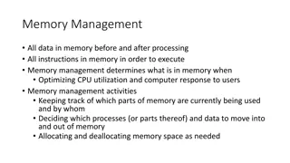
Understanding Computer Memory Systems and Organization
Memory systems in computer architecture play a crucial role in data storage and processing. They vary in purpose, performance, and capacity, from temporary storage like RAM to permanent storage. The main goal of a memory system is to ensure fast and uninterrupted access for the processor to enhance computational speed. Different types of memory, such as cache and virtual memory, are designed to optimize memory operations in computers.
- Computer Memory Systems
- Memory Addressing
- Cache Organization
- Computer Architecture
- Memory Operations

Download Presentation

Please find below an Image/Link to download the presentation.
The content on the website is provided AS IS for your information and personal use only. It may not be sold, licensed, or shared on other websites without obtaining consent from the author. Download presentation by click this link. If you encounter any issues during the download, it is possible that the publisher has removed the file from their server.
E N D
Presentation Transcript
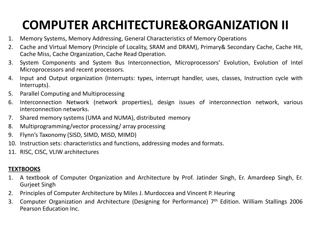
COMPUTER ARCHITECTURE&ORGANIZATION II Memory Systems, Memory Addressing, General Characteristics of Memory Operations Cache and Virtual Memory (Principle of Locality, SRAM and DRAM), Primary& Secondary Cache, Cache Hit, Cache Miss, Cache Organization, Cache Read Operation. System Components and System Bus Interconnection, Microprocessors Evolution, Evolution of Intel Microprocessors and recent processors. Input and Output organization (Interrupts: types, interrupt handler, uses, classes, Instruction cycle with Interrupts). Parallel Computing and Multiprocessing Interconnection Network (network properties), design issues of interconnection network, various interconnection networks. Shared memory systems (UMA and NUMA), distributed memory Multiprogramming/vector processing/ array processing Flynn s Taxonomy(SISD, SIMD, MISD, MIMD) 10. Instruction sets: characteristics and functions, addressing modes and formats. 11. RISC, CISC, VLIW architectures 1. 2. 3. 4. 5. 6. 7. 8. 9. TEXTBOOKS 1. A textbook of Computer Organization and Architecture by Prof. Jatinder Singh, Er. Amardeep Singh, Er. Gurjeet Singh 2. Principles of Computer Architecture by Miles J. Murdoccea and Vincent P. Heuring 3. Computer Organization and Architecture (Designing for Performance) 7thEdition. William Stallings 2006 Pearson Education Inc.
Memory Systems Memory refers to the internal storage areas of the computer. Literally defined as the faculty by which the mind stores and remembers information Humanly speaking, memory is our ability to encode, store and retain as well as subsequently recall information and past experience in the human brain. Memory is the sum total of what humans remember.
Memory Systems There are many different purposes for memory in the operation of a computer. Some memories are meant to store data and programs only while the computer is turned on; while other memories are meant to be permanent storage areas. Some memories perform better at the amount of data they can store, while others may provide quicker access time.
Memory Systems Every computer comes with a certain amount of physical memory usually referred to as main memory or RAM. We can think of main memory as an array of boxes, each of which can hold a single byte of information. A computer that has 1 megabyte of memory therefore can hold about 1 million bytes (or characters) of information.
Memory Systems The basic objective of a computer system is to increase the speed of computation. Likewise, the basic objective of a memory system is to provide fast, uninterrupted access for the processor to the memory such that the processor can operate at its expected speed.
Memory Systems The memory (internal storage) section of a computer is essentially an electronically operated file cabinet. It has a large number (usually several hundreds to thousands) of storage locations each referred to as storage address or registers. Every item of data and program instruction read into the computer during the loading process is stored or filed in a specific storage address.
Memory Systems Storage is nothing more than a collection of mailboxes each mail has a unique address and represents a location in memory. Just like the mailbox, the contents of a storage location can change but the number on the mailbox or memory address always remains the same.
In Summary 8 bits = 1byte 1024 bytes = 1 kilobytes (KB) 1024 Kilobytes =1 megabytes = 1 million bytes 1024 Megabytes =1 Gigabyte = 1 billion bytes 1024 gigabytes = 1 Terabytes = 1trillion bytes
KEY CHARACTERISTICS OF COMPUTER MEMORY SYSTEMS Location: Processor, Internal (main), External (secondary) Capacity: Word size, number of words Unit of Transfer: Word, Block Access Method: Sequential, Direct, Random, Associative Performance: Access time, Cycle time, Transfer rate Physical Type: Semiconductor, Magnetic, Optical, Magnetic-optical Physical Characteristics: Volatile/Non-volatile, Erasable/Non-erasable. Organization: memory modules
Characteristics of Memory Systems The complex subject of computer memory is made manageable if we classify memory subsystems characteristics. LOCATION: the term location refers to whether the memory is internal or external to the computer system. Internal memory is often equated with main memory, but there are other forms of internal memory. The processor requires its own local memory in the form of registers. The control unit portion of the processor may also require its own internal memory. Cache is another form of internal memory. External memory consists of peripheral storage devices such as disk and tape that are accessible to the processor via I/O controllers. according to their PHYSICAL TYPES: a variety of physical types of memory have been employed. The most common today are semiconductor memory, magnetic surface memory used for disk and tape and optical and magneto optical.
Characteristics of Memory Systems CAPACITY: another obvious characteristic of memory is its capacity. For internal memory, this is typically expressed in terms of bytes (1 byte= 8bits) or words. Common word lengths are 8, 16 and 32 bits. External memory capacity is typically expressed in terms of bytes. UNIT OF TRANSFER: a related concept is the unit of transfer. For internal memory, the unit of transfer is equal to the number of data lines into and out of the memory module. This may be equal to the word length, but is often larger such as: 64, 128 or 256 bits. For main memory, this is the number of bits read out of or written into memory at a time. The unit of transfer need not equal a word or an addressable unit. For external memory, data are often transferred in much larger units than a word and these are referred to as blocks.
Characteristics of Memory Systems ACCESS METHOD: another distinction among memory types is the method of accessing units of data. In a sequential access, memory is organized into units of data called records. Access must be made in a specific linear sequence. Stored addressing information is used to separate records and assist in the retrieval process. Tape units are sequential access. As with a sequential access, direct access involves a shared read-write mechanism. However, individual blocks or records have a unique address based on physical location and access is accomplished by direct access to reach a general vicinity plus sequential searching, counting, or waiting to reach the final location. Access time is variable: disk units are direct access. Random Access: each addressable location in memory has unique physically wired-in addressing mechanism. The time to access a given location is independent of the sequence of prior accesses and it is constant. Thus, any location can be selected at random and directly addressed and accessed. Main memory and some cache systems are random access. Associative: this is a random-access type of memory that enables one to make a comparison of desired bit locations within a word for a specified match and to do this for all words simultaneously. Thus, a word is retrieved based on a portion of its contents rather than its address. As with ordinary random-access memory, each location has its own addressing mechanism and retrieval time is constant independent of location or prior access patterns. Cache memories may employ associative access.
Characteristics of Memory Systems PERFORMANCE: From a user s point of view, the two most important characteristics of performance. memory are capacity and Transfer Rate: this is the rate at which data can be transferred into or out of a memory unit. For RAM, it is equal to 1/ cycle time while for non-RAM the following relationship holds: TN= TA+N/R where TN =Average time to read or write N bits TA=Average access time N= Number of bits R=Transfer Rate in bits per seconds (bps) Access Time (Latency): for RAM, this is the time it takes to perform a read or write operation. That is, the time from the instant that an address is presented to the memory to the instant that data is stored or made available for use. For non-random access memory, access time is the time it takes to position the read-write mechanism at the desired location.
Characteristics of Memory Systems Memory Cycle Time: this concept is primarily applied to RAM and consists of the access time plus any additional time required before a second access can commence. This additional time may be required for transients to die out on signal lines or to regenerate data if they are read destructively. Memory cycle time is concerned with the system bus, not the processor. ORGANIZATION: for RAM, the organization is a key design issue. Organization means the physical arrangement of bits to form words. There is need to organize data across hierarchy such that the percentage of accesses to each successively lower level is substantially less than that of the level above.
Characteristics of Memory Systems PHYSICAL CHARACTERISTICS: characteristics of data storage are important. In a volatile memory, information decays naturally or is lost when electrical power is switched off, while in a non-volatile memory, information once recorded remains without deterioration until deliberately changed, no electric power is needed to retain information. Magnetic-surface memories are non- volatile, semi-conductor memory may be either volatile or non-volatile. cannot be altered except by destroying the storage unit. Semi-conductor memory of this type is known as read-only memory (ROM). several physical Non-erasable memory
Some Definitions A memory module is a narrow printed circuit board that holds memory chips. That is, a printed circuit board on which memory integrated circuits are mounted. Common memory modules is DIMM (dual in-line memory modules) Block: minimum amount of information that can be in a cache. Records: collection of data items arranged for processing by a program. Multiple records are contained in a file or data set.
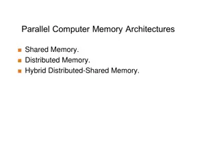
MEMORY HIERACHY Although seemly simple in concept, computer memory exhibits perhaps the widest range of type, technology, organization, performance and cost of any feature of a computer system. No technology is optimal in satisfying the memory requirements for a computer consequence, the typical equipped with a hierarchy of memory subsystems, some internal to the system (directly accessible by the processor) and some external (accessible by the processor via an I/O module) system. As a is computer system
MEMORY HIERACHY Programmers want very large memory with low latency (time- interval) the solution is to organize memory system into a hierarchy. Computer memory is organized into hierarchy. At the highest level (close to the processor) are the processor registers. Next comes one or more levels of cache, when multiple levels are used, they are denoted L1, L2 ; next comes main memory which is usually made out of dynamic random access memory (DRAM). All of these are considered internal to the computer system. The hierarchy continues with external memory with the next level typically being a fixed hard disk and one or more levels below that consisting of removable media such as optical disks and tape.
MEMEORY HIERACHY REGISTERS CACHE MEMORY MAIN MEMORY DISK STORAGE
MEMORY HIERACHY As one goes down the memory hierarchy, there is decreasing cost/bit, increasing capacity and slower access time. The design challenge is to organize the data and programs in memory so that the accessed memory words are usually in the faster memory. In general, it is likely that most future accesses to main memory by the processor will be to locations recently accessed. So the cache automatically retains a copy of some of the recently used words from the DRAM. If the cache is designed properly, then most of the time the processor will request memory words that are already in the cache.
MEMORY HIERACHY As one goes down the hierarchy the following happen: a. Decreasing cost per bit b. Increasing capacity c. Decreasing frequency of access of the memory by the processor Designers would like to use memory technologies that provide for large capacity memory, both because the capacity is needed and because the cost per bit is low. However, to meet performance requirement, the designer needs to use expensive relatively lower-capacity memories with short access times. The way out of this dilemma is not to rely on a single memory component or technology, but to employ a memory hierarchy.
MEMORY HIERACHY Memory hierarchies prevent programs from having absolutely performances. Registers and Cache put frequently used instructions and data in fast memory to operate at the speed of processor. Main memory and disk have larger memory storage options for information. abysmal (very bad) all frequently used
REGISTERS A register is a group of flip-flopswith each flip-flop capable of storing information. In addition to the flip-flops, a register may have combinational gates that perform certain data processing tasks. So a register consists of a group of flip-flops and gates that effect their transition. The flip-flops hold the binary information and the gates control when and how new information is transferred into the register.
Micro-Operations The operations executed on data stored in registers are called micro-operations. A micro-operation is an elementary performed on the information stored in one or more registers. The result of the operation may replace the previous binary information of a register or may be transferred to another register. A micro-operation requires only one clock pulse for execution if the operation is done in parallel.
Categories of Micro-operations The micro-operations most often encountered in digital computers are classified into four categories: Register Transfer Micro-operations: transfer binary information from one register to another. Arithmetic Micro-operations: perform arithmetic operation on numeric data stored in register. Logic micro-operations: perform bit manipulation operations on non-numeric data stored in registers. Shift micro-operations: perform shift operations on data stored in registers.
Computer Registers Accumulator (AC): the accumulator is a general purpose processing register. The significance of a general purpose register is that, it can be referred to in instructions. e.g load AC with the contents of a specific memory location; Store the contents of AC into a specified memory location
Computer Registers Instruction Register (IR): the instruction read form memory is placed in IR. It contains the 16-bit op code instruction being executed. Temporary Registers (TR): the temporary register is used for holding temporary data during processing. Address Register: in a direct or Indirect addressing the processor needs to keep track of what locations in memory it is addressing. The address register is used for this. The memory address register holds the address for memory. AR is a 12-bit register in basic computer. It specifies the address in memory of the word to be written from or read into the MBR.
Computer Registers Programme Counter: a register that holds the address of the next instruction-pair to be fetched/read from memory after the current instruction is executed. INPR: this register is used for input. The input register receives an 8-bit character from an input device. OUTR: this register is used for output. The output register holds an 8-bit character for an output device.
Computer Registers Data Register: when an operand is found using either direct or indirect addressing, it is placed in the Data Register (DR). The processor then uses this value as data for its operation. The data register holds the operand read from the memory. Memory Buffer Register (MBR): contains a word to be stored in memory or sent to the I/O unit or is used to receive a word from memory or from the I/O unit.
Computer Registers The fastest, smallest and most expensive type of memory consists of the registers internal to the processor. Typically, a processor will contain a few dozen of such registers although some machines contain hundreds of registers.
Register Symbol Number of bits Register Functions DR 16 Data Register : holds memory operand AR 12 Address Register: holds address for memory AC 16 Accumulator : processor register IR 16 Instruction Register: holds instruction code PC 12 Programme Counter: holds address of instructions TR 16 Temporary Register: holds temporary data INPR 8 Input Register: holds input character OUTPR 8 Output Register: holds output character
Instructions An instruction is a command to the microprocessor to perform a given task on specified data. Each instruction has two parts: The task to be performed (OPCODE) The data to be operated on (Operand) Types of Instructions 1. CLR: reset value of a working variable to zero 2. MOVE: move data between registers and memory: MOV 1835 (target) 1000 (source) 3. ADD: for addition: Add A, #25h; add the number 25h to A and put the sum in A. ADD A, R3; add the register R3 value to A, put the sum in A. 4. Subtract instruction 5. Jump Instruction etc.
Simplify A = (13-9) * 8 MOV B, #9; MOV A, #13; move the no 13 to register A SUB A,B; subtract 9 form 13 and store the result in A MUL A, #8; multiply the value in register A by 8 and store the result in A move the no 9 to register B


 * 8")