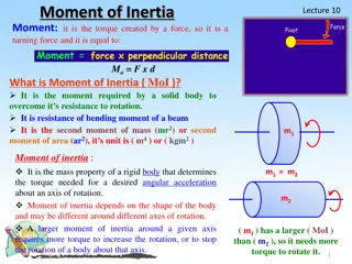
Understanding Force Couples and Their Applications in Mechanics
Force couples, generated by equal and opposite forces, produce rotational effects without any net translation. They possess unique properties and find significant applications in mechanics. Couples have a constant magnitude regardless of the distance between forces, making them independent of the location of the moment center. The concept of equivalent couples and force couple systems are explored, illustrating how couples can be used to represent the combined effect of a force and a tendency to rotate a body.

Download Presentation

Please find below an Image/Link to download the presentation.
The content on the website is provided AS IS for your information and personal use only. It may not be sold, licensed, or shared on other websites without obtaining consent from the author. Download presentation by click this link. If you encounter any issues during the download, it is possible that the publisher has removed the file from their server.
E N D
Presentation Transcript
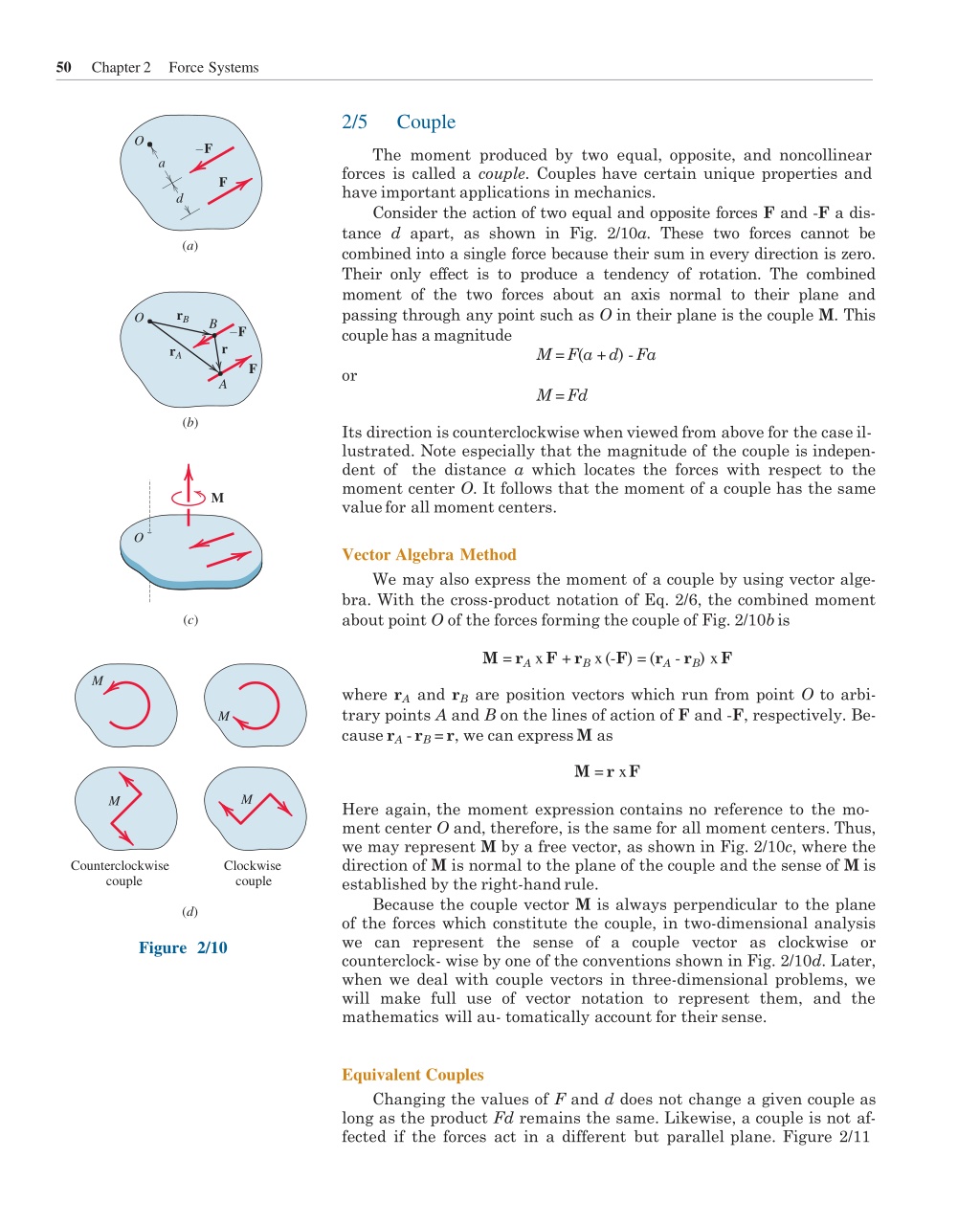
50 Chapter 2 Force Systems 2/5 Couple O F The moment produced by two equal, opposite, and noncollinear forces is called a couple. Couples have certain unique properties and have important applications in mechanics. Consider the action of two equal and opposite forces F and -F a dis- tance d apart, as shown in Fig. 2/10a. These two forces cannot be combined into a single force because their sum in every direction is zero. Their only effect is to produce a tendency of rotation. The combined moment of the two forces about an axis normal to their plane and passing through any point such as O in their plane is the couple M. This couplehas amagnitude M =F(a +d) -Fa or M =Fd a F d (a) rB O B F r rA F A (b) Its direction is counterclockwise when viewed from above for the caseil- lustrated. Note especially that the magnitude of the couple is indepen- dent of the distance a which locates the forces with respect to the moment center O. It follows that the moment of a couple has the same valuefor all moment centers. M O Vector Algebra Method We may also express the moment of a couple by using vector alge- bra. With the cross-product notation of Eq. 2/6, the combined moment about point O of the forces forming the couple of Fig. 2/10bis (c) M =rAxF +rBx(-F) =(rA-rB) xF M where rAand rBare position vectors which run from point O to arbi- trary points A and B on the lines of action of F and -F, respectively. Be- causerA-rB=r, we can expressM as M M =r xF M M Here again, the moment expression contains no reference to the mo- ment center O and, therefore, is the same for all moment centers. Thus, we may represent M by a free vector, as shown in Fig. 2/10c, where the direction of M is normal to the plane of the couple and the sense of M is established by the right-handrule. Because the couple vector M is always perpendicular to the plane of the forces which constitute the couple, in two-dimensional analysis we can represent the sense of a couple vector as clockwise or counterclock- wise by one of the conventions shown in Fig. 2/10d. Later, when we deal with couple vectors in three-dimensional problems, we will make full use of vector notation to represent them, and the mathematics will au- tomatically account for their sense. Counterclockwise couple Clockwise couple (d) Figure 2/10 Equivalent Couples Changing the values of F and d does not change a given couple as long as the product Fd remains the same. Likewise, a couple is not af- fected if the forces act in a different but parallel plane. Figure 2/11
Couple 51 Article 2/5 M M M M 2F F d /2 F d 2F F F d d F F Figure 2/11 shows four different configurations of the same couple M. In each of the four cases, the couples are equivalent and are described by the same free vector which represents the identical tendencies to rotate the bodies. Force Couple Systems The effect of a force acting on a body is the tendency to push or pull the body in the direction of the force, and to rotate the body about any fixed axis which does not intersect the line of the force. We can repre- sent this dual effect more easily by replacing the given force by an equal parallel force and a couple to compensate for the change in the moment of the force. The replacement of a force by a force and a couple is illustrated in Fig. 2/12, where the given force F acting at point A is replaced by an equal force F at some point B and the counterclockwise couple M = Fd. The transfer is seen in the middle figure, where the equal and opposite forces F and -F are added at point B without introducing any net exter- nal effects on the body. We now see that the original force at A and the equal and opposite one at B constitute the couple M = Fd, which is counterclockwise for the sample chosen, as shown in the right-hand part of the figure. Thus, we have replaced the original force at A by the same force acting at a different point B and a couple, without altering the ex- ternal effects of the original force on the body. The combination of the force and couple in the right-hand part of Fig. 2/12 is referred to as a force couple system. By reversing this process, we can combine a given couple and a force which lies in the plane of the couple (normal to the couple vector) to produce a single, equivalent force. Replacement of a force by an equiva- lent force couple system, and the reverse procedure, have many applica- tions in mechanicsand should be mastered. B F F B B F d F F A A M = Fd Figure 2/12
52 Chapter 2 Force Systems SAMPLE 2/7 PROBLEM M The rigid structural member is subjected to a couple consisting of the two 100-N forces. Replace this couple by an equivalent couple consisting of the two forces P and +P, each of which has a magnitude of 400 N. Determine the proper angle O. 40 P 0 0 -P 100 Solution. The original couple is counterclockwisewhen the plane of the forces is viewedfrom above, and its magnitude is 100 [M =Fd] M =100(0.1) =10 N m The forces P and +P produce a counterclockwisecouple 100 60 M =400(0.040) cos O 100 N O Equating the two expressions gives 100 N 10 =(400)(0.040) cos O Dimensions in millimeters O =cos+110=51.3 Ans. P = 400 N 16 0 Helpful Hint O Since the two equal couples are parallel free vectors, the only dimensions which are relevant are those which give the perpendicular distances between the forces of the couples. 40 mm d0 0 P = 400 N SAMPLE PROBLEM 2/8 80 lb Replace the horizontal 80-lb force acting on the lever by an equivalent sys- tem consistingof a force at O and a couple. 9 60 0 Solution. We apply two equal and opposite 80-lb forces at O and identify the counterclockwisecouple [M =Fd] M =80(9 sin 60 ) =624 lb-in. Ans. 80 lb 80 lb O Thus, the original force is equivalent to the 80-lb force at O and the 624-lb-in. couple as shown in the third of the three equivalent figures. Helpful Hint O The reverse of this problem is often encountered, namely, the replacement of a force and a couple by a single force. Proceeding in reverse is the same as replacing the couple by two forces, one of which is equal and opposite to the 80-lb force at O. The moment arm to the second force would be M/F = 624/80 = 7.79 in., which is 9 sin 60 , thus determining the line of action of the single resultant force of 80 lb. 0 0 0 80 lb 80 lb 80 lb 624 lb-in.
Article 2/5 Problems 53 PROBLEMS 2/61 Replace the force couple system at point O by a single force. Specify the coordinate yAof the point on the y-axis through which the line of action of this resultant force passes. Introductory Problems 2/59 Compute the combined moment of the forces about (a) point O and (b) point A. two 90-lb y y 90 lb x 200 N O 80 N m x A O Problem 2/61 8 4 4 The top view of a revolving entrance door is shown. Two persons simultaneously approach the door and exert force of equal magnitudes as shown. If the resulting moment about the door pivot axis at O is 25 N r m, determine the force magnitude F. 2/62 90 lb Problem 2/59 2/60 Replace the 12-kN force acting at point force couple systemat (a) point O and (b) point B. A by a 15 F y 0.8 m 12 kN 0.8 m O 4 m 30 x A O F 5 m 15 Problem 2/62 B Problem 2/60
54 Chapter 2 Force Systems Determine the moment associated with the couple applied to the rectangular plate. Reconcile the results with those for the individual special cases of O =0, b =0, and h =0. The 7-lb force is applied by the control rod on the sector as shown. Determine the equivalent force couple systemat O. 2/63 2/65 T = 7 lb F 30 A h 15 15 O b 3" F Problem 2/63 Problem 2/65 As part of a test, the two aircraftenginesare revved up and the propeller pitches are adjusted so as to re- sult in the fore and aft thrusts shown. What force F must be exerted by the ground on each of the main braked wheels at A and B to counteract the turning effect of the two propeller thrusts? Neglect any ef- fects of the nose wheel C, which is turned 90 and unbraked. 2/64 Replace the 10-kN force acting on the steel column by an equivalent force couple system at point O. This replacement is frequently done in the design of structures. 2/66 10 kN 75 mm 75 1 m 1 500 lb O A 8 14 Problem 2/66 C B lb 500 Problem 2/64
Article 2/5 Problems 55 2/67 Each propeller of the twin-screw ship develops a full-speed thrust of 300 kN. In maneuvering the ship, one propeller is turning full speed ahead and the other full speed in reverse. What thrust P must each tug exert on the ship to counteract the effect of the ship s propellers? A lug wrench is used to tighten a square-headbolt. If 50-lb forces are applied to the wrench as shown, determine the magnitude F of the equal forces exerted on the four contact points on the 1-in. bolt head so that their external effect on the bolt is equivalent to that of the two 50-lb forces. Assume that the forces are perpendicular to the flats of the bolt head. 2/69 50 m 1 F 12 m 50 lb F A C View C Detail (clearancesexaggerated) 120 m 14 50 lb Problem 2/67 B 14 Representative Problems Problem 2/69 2/68 The force couple system at A is to be replaced by a single equivalent force the vertical edge (or its extension) of the triangular plate.Determinethe distance d betweenA and B. acting at a point B on 2/70 A force couple system acts at O on the 60 circular sector. Determine the magnitude of the force F if the given system can be replaced by a stand-alone force at corner A of the sector. MA A R d F F h B 60 b 80 N m 0.4 m O A Problem 2/68 Problem 2/70
56 Chapter 2 Force Systems 2/71 During a steady right turn, a personexertsthe forces shown on the steering wheel. Note that each force consists of a tangential component and a radially- inward component. Determine the moment exerted about the steeringcolumn at O. The tie-rod AB exerts the 250-N force on the steer- ing knuckle AO as shown. Replace this force by an equivalent force couple systemat O. 2/73 10 F = 250 N 235 mm 8 N y 30 B x O A 50 mm 50 m 15 A 15 B O 30 8 N 375 mm Problem 2/73 The 250-N tension is applied to a cord which is se- curely wrapped around the periphery of the disk. Determine the equivalent force couple system at point C. Begin by couple systemat A. 2/74 Problem 2/71 2/72 A force F of magnitude 50 N is automobile parking-brake lever at the position x =250 mm. Replace the force by an equivalent force couple systemat the pivot point O. exerted on the finding the equivalent force 120 mm F 20 45 15 200 mm A 10 B 250 N O 400 mm Problem 2/72 60 60 D C Problem 2/74
Article 2/5 Problems 57 2/75 The system consisting of the bar OA, two identical pulleys, and a section of thin tape is subjected to the two 180-N tensile forces shown in the figure. Deter- mine the equivalent force couple systemat point O. The device shown is a part of an automobile seat- back-release mechanism. The part is subjected to the 4-N force exerted at A and a 300- N r mm restor- ing moment exerted by a hidden torsional spring. Determine the y-intercept of the line of action of the singleequivalent force. 2/77 180 N r y F = 4 N A 10 mm r = 25 mm 15 A 40 mm 100 mm r 180 N x O 300 N mm 45 O 50 mm Problem 2/77 2/78 The force F acts along line MA, where M is the mid- point of the radius along the x-axis. Determine the equivalent force couple systemat O if O =40 . Problem 2/75 2/76 Points A and B are the midpointsof the sidesof the rectangle.Replacethe given force F acting at A by a force couple systemat B. y F y F A A x M O h B x O b R 2 2 R Problem 2/76 Problem 2/78