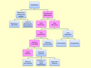
Evolution of Interface Fracture Mechanics: A Historical Perspective
Interface Fracture Mechanics has evolved over the years with significant contributions from researchers like Griffith, Irwin, and Williams. The early years focused on linear elastic fracture mechanics, leading to the development of stress intensity factors and understanding crack propagation. Specific boundary value problems related to interface cracks were solved between 1963 and 1965, providing insights into stress behavior near crack tips. This historical perspective showcases the advancements in studying crack behavior along interfaces in different materials.

Download Presentation

Please find below an Image/Link to download the presentation.
The content on the website is provided AS IS for your information and personal use only. It may not be sold, licensed, or shared on other websites without obtaining consent from the author. Download presentation by click this link. If you encounter any issues during the download, it is possible that the publisher has removed the file from their server.
E N D
Presentation Transcript
Interface Fracture Mechanics a la Rice: An Historical Perspective Leslie Banks-Sills Dreszer Fracture Mechanics Laboratory School of Mechanical Engineering Tel Aviv University Israel
Outline Linear elastic fracture mechanics Interface fracture mechanics-early years Comninou -1977 to 1979 Rice 1988 2 2
Fracture Mechanics Griffith-the grandfather of fracture mechanics- showed that the stresses at the tip of a crack behave as the inverse square-root of the crack length1. He also presented an energetic criterion for crack propagation. The next major step in understanding fracture mechanics takes place when the first term of the asymptotic expansion for the stress and displacements in the neighborhood of a crack tip is developed by Williams2and Irwin3. o o 1. Griffith, A.A. The phenomena of fracture and flow in solids. Phil. Trans. R. Soc., A221 (1921) 163-198. Williams, M.L. On the stress distribution at the base of a stationary crack. J. Appl. Mech., 24 (1957) 109-114. Irwin, G.R. Analysis of stresses and strains near the end of a crack traversing a plate. J. Appl. Mech., 24 (1957) 361-364. 2. 3 3.
Fracture Mechanics Irwin-the father of fracture mechanics-defined the stress intensity factors , and 4. K o K K II I III 4. Irwin, G.R. Fracture. In: Encyclopedia of Physics, Vol. VI, S. Flugge (ed.) Springer, Germany, (1958) pp. 551-590. 4
Interface Fracture Mechanics The behavior of the stress and displacements in the neighborhood of a crack tip for a crack along an interface between two dissimilar linear elastic, isotopic and homogeneous materials was determined by Williams5. o r sin( ln ) r sin( ln ) 1 u r r cos( ln ) r cos( ln ) r 1 + + 1 2 1 = = ln 2 2 + + 1 2 3 4 3 plane = = , k 1, 2 shear moduli Poisson s ratios k k = = - k k plane = = , k 1, 2 + + 1 k k 5 5. Williams, M.L. The stresses around a fault or crack in dissimilar media. Bull. Seismol. Soc. Am., 49 (1959) 199-204.
Interface Fracture Mechanics Between 1963 and 1965, a number of papers appeared solving specific boundary value problems related to interface cracks6-10. The first term of the asymptotic expansion for the stresses was determined. It was noted that the oscillatory stress behavior was relegated to a small region near the crack tip. o 6. Erdogan, F. Stress distribution in a nonhomogeneous elastic plane. J. Appl. Mech., 30 (1963) 232-236. Sih, G.C., Rice, J.R. The bending of plates of dissimilar materials with cracks. J. Appl. Mech., 31 (1964) 477-482. Rice, J. R., Sih, G.C. Plane problems of cracks in dissimilar media. J. Appl. Mech., 32 (1965) 418-423. England, A.H. A crack between dissimilar media. J. Appl. Mech., 32 (1965) 400-402. 10. Erdogan, F. Stress distribution in bonded dissimilar materials with cracks. J. Appl. Mech., 32 (1965) 403-410. 7. 8. 9. 6
Interface Fracture Mechanics In [8], this problem was solved by Rice and Sih. The stress intensity factors were written in a different form. But in current notation, they were found as ( ( iK K K + + = = + + = = 22 2 1 ) )( ( ) ) ( ( ) ) i 21 i + + i a a 1 2 2 = = i 1 where Applied stresses in the x1-direction were determined to provide displacement continuity across the interface E E E 3 3 k plane strain 22 (2) 11 (1) 11 2 2 1 2 = = + + = = E 2 k 1 E k + + + + 1 1 E E 2 1 1 1 generalize plane d stress k It was noted that these stress intensity factors no longer represent modes I and II deformation. The in-plane deformation is coupled. 7 8. Rice, J. R., Sih, G.C. Plane problems of cracks in dissimilar media. J. Appl. Mech., 32 (1965) 418-423.
Interface Fracture Mechanics In [9], it was found again that stress oscillations were confined to a small distance from the crack tip. It was also found that crack face interpenetration was within a small distance from the crack tip. The region was estimated to be O(10-4)2a. It was noted that this is sufficiently small so that it may be neglected. Thus, solution to these problems may be a good approximation of physical problems. It was mentioned in passing that shear deformation will also produce a small interpenetration zone. This is not the case. In [10], it was stated that for an interface crack subjected to tension, the stress oscillations are confined to a small region. For an interface crack between glass and steel, crack face interpenetration begins at a distance of O(10-7)a from the crack tip10. 9. England, A.H. A crack between dissimilar media. J. Appl. Mech., 32 (1965) 400-402. 10. Erdogan, F. Stress distribution in bonded dissimilar materials with cracks. J. Appl. Mech., 32 (1965) 403-410. 8
Interface Fracture Mechanics In [11], again it was shown that the stress oscillations were confined to a small distance from the crack tip. It was also found that crack face interpenetration was also within a small distance from the crack tip. Again shear deformation was neglected. It was pointed out that instead of an interpenetration zone, a contact zone would actually occur. The authors also bring reference [12] to our attention in which some preliminary work was already carried out to obtain the fields. The main contribution of [11] is the relation between the interface energy release rate and the stress intensity factors in two-dimensions. Here it is in current notation ( ( ) ) 1 1 1 2 1 2 2 = = + + + + K K G i 2 E E cosh 2 1 2 11. Malyshev, B.M., Salganik, R.L. The strength of adhesive joints using the theory of cracks. Int. J. Fract. Mech., 1 (1965) 114-128. 12. Cherepanov, G.P. The stress state in a heterogeneous plate with slits. Ivestia AN SSSR, OTN, Mekhan. i Mash., 1 (1962) 131-137 (in Russian). 9
Interface Fracture Mechanics It would appear that as a result of the oscillatory stresses in the neighborhood of the crack tip and crack face interpenetration that the fracture mechanics community lost interest in this subject. In 1971, two papers appeared [13,14] which considered layered material, with an interface crack as a limiting case. In 1976, the finite element method was applied to an interface crack [15]. 13. Erdogan, F. and Gupta, G. The stress analysis of multi-layered composites with a flaw. Int. J. Solids Struct., 7 (1971) 39-61. 14. Erdogan, F., Gupta, G.D. Layered composites with an interface flaw. Int. J. Solids Struct., 7 (1971) 1089-1107. 15. Lin, K.Y., Mar, J.W. Finite element analysis of stress intensity factors for cracks at a bi-material interface. Int. J. Fract., 12 (1976) 521-531. 10
Interface Fracture Mechanics After this hiatus, Comninou in a series of papers assumes that instead of crack face interpenetration, there is a contact zone of length s between the crack faces. In [16], she shows that for far field applied tension, the length of the contact zone is between 10-7a and 10-4a depending on mechanical properties. The contact zone was smaller than the interpenetration zone. In [17] for pure applied far field shear, it is shown that the contact zone length is smaller than that for pure tension at one crack tip, but 2a/3 at the other crack tip. The side at which the larger contact zone exists depends on material properties and the direction of the shear stress. The small contact zone is larger than the interpenetration zone. 16. Comninou, M. The interface crack. J. Appl. Mech., Vol. 44 (1977) pp. 631-636. 17. Comninou, M. The interface crack in a shear field. J. Appl. Mech., Vol. 45 (1978) pp. 287-290. 18. Comninou, M., Schmueser, D. The interface crack in a combined tension- compression and shear field. J. Appl. Mech., Vol. 46 (1979) pp. 345-348. 11
Interface Fracture Mechanics Jim Rice Use of the approach developed by Comninou for other geometries is not practical. Instead, in 1988, Rice returns to the problem of an interface crack giving guidance on how to solve the problem. Using Muskhelishvili methods, the potential functions for the interface crack problem are obtained. The tractions along the interface are i Kr 2 ( ( ) ) = = + + K K iK + + i = = 1 2 22 21 = = 0 r Along the crack faces r 4 1 1 (1) i (2) i = = , r u u , r u ( - ) ( ) ir + + i = = + + u u K ( ( ) ) i 2 1 + + i 2 1 2 cosh E E 1 2 12 19. Rice, J.R. Elastic fracture mechanics concepts for interfacial cracks. J. Appl. Mech., 55 (1988) 98-103.
Interface Fracture Mechanics The validity of the first term of the asymptotic expansion is examined in terms of the size of the region of crack face interpenetration. 22 21 i + + i = = Te Setting along the crack faces leads to the length of the contact zone u 2= = 0 1 = = + + rc a 2 exp - 2 Since , with 0 1 2 a rc / 1 if / / 4 2 The interpenetration zone is small. 13 19. Rice, J.R. Elastic fracture mechanics concepts for interfacial cracks. J. Appl. Mech., 55 (1988) 98-103.
Interface Fracture Mechanics The oscillatory parameter 1 + + 1 2 1 = = ln 2 2 + + 1 2 Let us examine Take material 1 to be cork, so that Take material 2 to be stiff, so that 1 1 0 0 2 = = 175 0. Then, 175 0. = = 075 0. Si02/Al2O3 , = = 011 0. Si/Cu , 14 19. Rice, J.R. Elastic fracture mechanics concepts for interfacial cracks. J. Appl. Mech., 55 (1988) 98-103.
Interface Fracture Mechanics If one wishes to duplicate the crack tip conditions for two bodies with different crack lengths, one must apply different loading conditions to each body. If the crack length is 2a and so that i = = + + 21 22 i = = + + 21 22 = = 0 i Te T For a crack of length shear loading are required to have the same complex stress intensity factor K. , both tensile and ' a 2 This means that it is not possible to separate opening and in- plane sliding modes. This is different than that for cracks in homogeneous materials where modes I and II stress intensity factors are written as and . II K K I 15 19. Rice, J.R. Elastic fracture mechanics concepts for interfacial cracks. J. Appl. Mech., 55 (1988) 98-103.
Interface Fracture Mechanics The units of the complex stress intensity factor K are i - MPa m (m) Changing units from meters to millimeters changes the ratio of K / K 2 1 Thus, opening and sliding modes are inherently coupled. Normalize the units as K K K K K i K i i L iL MPa m = = = = + + + + = = = = K K I 1 II 2 where is an arbitrary length scale. L It should be a constant and not a function of the crack length. L has been used to correlate failure data with a failure criterion20. 19. Rice, J.R. Elastic fracture mechanics concepts for interfacial cracks. J. Appl. Mech., 55 (1988) 98-103. 20. Banks-Sills, L., Travitzky, N., Ashkenazi, D. Interface fracture properties of a bimaterial ceramic composite. Mech. Mater., 32 (2000) 711-722. 16
In-Plane Stress Field In-plane stress field ( ( ) ) ( ( ) ) 1 ) + + ) ( ( i i k = = , , 1 2 ( ) ( ) Kr Kr k k 2 r = = , 1, 2 = + K K iK = = i 1 1 2 2x + + + + 1ln 2 = = 1 2 1 , , r 1 1 1 2 1 2 1x material , , 2 2 2 3 4 3 plane strain k = = 1, 2 interface k = = 17 19. Rice, J.R. Elastic fracture mechanics concepts for interfacial cracks. J. Appl. Mech., 55 (1988) 98-103. 21. Rice, J.R., Suo Z., Wang J.S. Mechanics and thermodynamics of brittle interfacial failure in bimaterial systems. In: Metal Ceramic Interfaces. R hle, M., Evans, A.G., Ashby, M.F. and Hirth, J.P. (eds.) Pergamon Press, New York, (1990) pp. 269-294. k k plane stress + + 1 k 16
Out-of-Plane Stress Field K ( ( ) ) k = = ( III 3 ) III k 3 2 r 2x = = 1, 2 , , r 1 1 1 1x , , 2 2 2 interface k = = 1, 2 material 18 22. Deng, X. General crack-tip fields for stationary and steadily growing interface cracks in anisotropic bimaterials. J. Appl. Mech., 60 (1993) 183-196.
Interface Fracture Mechanics The phase angle of the stress intensity factors is defined as ( ( ( ( K ) ) ) ) K L i K 2 = = = = arctan arctan K L i 1 L L A change of the length parameter from to translates the phase angle as A B L A = = + + ln A B L B 19. Rice, J.R. Elastic fracture mechanics concepts for interfacial cracks. J. Appl. Mech., 55 (1988) 98-103. 19
Interface Fracture Mechanics For two dissimilar anisotropic materials, it is possible that the square-root, oscillatory singularity is related to the in-plane deformation and the square-root singularity is related to the out-of-plane deformation , iK K K 2 = = 1+ + K III But it is also possible that the shear deformation, both in-plane and out-of-plane, are coupled with a complex stress intensity factor given by iK K K + + = = 2 3 In fact, there may be three stress intensity factors related to the square-root, oscillatory singularity and three related to the square-root singularity23 K , K , K K , K , K and I II III 1 2 3 21. Rice, J.R., Suo Z., Wang J.S. Mechanics and thermodynamics of brittle interfacial failure in bimaterial systems. In: Metal Ceramic Interfaces. R hle, M., Evans, A.G., Ashby, M.F. and Hirth, J.P. (eds.) Pergamon Press, New York, (1990) pp. 269-294. 23. Banks-Sills, L., Ikeda, T. Stress intensity factors for interface cracks between orthotropic and monoclinic material. Int. J. Fract., 167 (2011) 47-56. 20
Interface Fracture Mechanics A failure criterion was proposed based on G = = ( ) G c where ( ( ( ( ) ) ) ) K L i K 2 = = = = arctan arctan K L i K 1 21. Rice, J.R., Suo Z., Wang J.S. Mechanics and thermodynamics of brittle interfacial failure in bimaterial systems. In: Metal Ceramic Interfaces. R hle, M., Evans, A.G., Ashby, M.F. and Hirth, J.P. (eds.) Pergamon Press, New York, (1990) pp. 269-294. 21
Interface Fracture Mechanics Failure Criterion Carry out fracture toughness tests. Obtain the critical load Pcand the critical crack length ac. Calculate the stress intensity factors K1 andK2 . Calculate the interface energy release rate Choose ( ( ) ) 1 H = = + + 2 1 2 2 G K K i 1 L Gic ( ( ( ( ) ) ) ) L i 1 K = = -1 tan L 1 i 1 K K iL 1 = = K G G = = 1+ + 1 2 ) tan K ( ic c 1 2 G average c 1 H 1 ( ) L 22 1 24. L. Banks-Sills, L., Ashkenazi, D. A note on fracture criteria for interface fracture. Int. J. Fract. 103 (2000), 177-188.
Interface Fracture Mechanics Failure Criterion L ( ( ) ) 1 H = = + + = = + + 2 1 2 2 2 ln G K K L 2 1 i 1 Gic G G = = 1+ + 2 ) tan ( ic c 1 failure curve K 2 1 G average c 1 H failure K = = -1 2 tan K 1 safe 2 ( ) 23 L 2 24. L. Banks-Sills, L., Ashkenazi, D. A note on fracture criteria for interface fracture. Int. J. Fract. 103 (2000), 177-188.
Any questions? L. Banks-Sills and A. Sedmak, "Linear Elastic and Elasto-Plastic Aspects of Interface Fracture Mechanics", Structural Integrity and Life, 20 (2020) 203-210. 24
Book 25
Crevasse 27