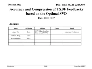
Developing Common Metrics and Models for RF Overhead Calculations

Issues surrounding power overhead in RF engineering, optimizing design power budget, understanding losses and disturbances, simulations, meaningful measurements, and future plans for the ILC. Topics covered include power requirements, cost optimization, accelerator section costs, static losses, and disturbance categories.

Download Presentation

Please find below an Image/Link to download the presentation.
The content on the website is provided AS IS for your information and personal use only. It may not be sold, licensed, or shared on other websites without obtaining consent from the author. Download presentation by click this link. If you encounter any issues during the download, it is possible that the publisher has removed the file from their server.
E N D
Presentation Transcript
Developing Common Metrics and Models for RF Overhead Calculations Brian Chase FNAL Presenter for ILC LLRF Team
Overview Issues surrounding power overhead Value engineering (performance vs. capital expense) Optimize design Power budget Understanding losses and disturbances Models Global and local RF station Simulations Metrics how to make meaningful measurements 9mA tests and other system tests Extrapolate to ILC Plans going forward 2 9/11/2024 LCWS08 B. Chase
Power Requirements Based on Maximum Gradient and Maximum Beam Current Current Limited Beam Current (mA) Design Goal Gradient limited Quench Operation Region Current test Gradient (MV/m) Peak power is only required at peak gradient and beam current Goal: Meet design requirements with minimal power overhead (cost) Could operation ever go outside of the design operation region? 3 9/11/2024 LCWS08 B. Chase
Accelerator Section Cost/Gradient vs. Klystron max Power Cost/Unit Gradient ~8:1 ratio in linear cost of Linac to RF power Power limited Region Quench Gradient limited Available RF Power Best power match while meeting regulation Example: If the last half of cryomodule production increased gradient to 33MV/m and we increased available power to match save $## in capital expense 4 9/11/2024 LCWS08 B. Chase
5 9/11/2024 LCWS08 B. Chase
Static Losses Distribution Loss Mostly the same for all Stations Cavity Gradient Variation Dependent on Cavity quench limit Parameter Variation Dependent on Ql match Peak Power Headroom Same for all klystrons Slow Thermal Drifts Generate Vector Sum errors There are few statistics available on these losses 6 9/11/2024 LCWS08 B. Chase
Disturbance Categories Narrowband or static errors Broadband (noise) Lorentz Force and microphonic detuning System, Receiver and ADC noise * gain Parameter variation Transmitter and Drive amplifier Waveguide loss Klystron modulator ripple Beam current fluctuations Spurious noise sources Static or phase modulating disturbances subtract in linear power Amplitude modulating noise sources subtract in linear voltage Non linear system responses cause AM - PM conversion and coupling in feedback loops 7 9/11/2024 LCWS08 B. Chase
RF Station Power Budget (Straw-man Proposal) 8 9/11/2024 LCWS08 B. Chase
Model for Overhead Power We develop a model that we use to estimate the required RF overhead given: Performance requirements Regulation of beam energy and jitter Reliability and exception rate Measured or calculated losses Measured noise spectrum (rms, spectrum, peak, etc) We use measurements at FLASH etc to help develop and validate the model and power budget Output would be a series of graphs, eg Overhead requirements vs. noise power Overhead vs. percentage of time within spec System response to noise + ramp into a compression stage 9 9/11/2024 LCWS08 B. Chase
Models and Simulators Accepted model for the cavities (Tesla) Dependent on dressed cavity design Model for HLRF is dependent on: Drive amplifier Modulator type and specification klystron (3 types) Distribution scheme Model for LLRF is dependent on Design variations Distribution scheme Present simulator features: Cavity, klystron response, Ql, Pk Drive amp response, receiver noise Goal: A common Matlab simulator for general use We are fairly close 10 9/11/2024 LCWS08 B. Chase
Supervisory Control of Energy Regulation Supervisory controller is needed to respond to exceptions and accumulated errors to meet the 0.1% energy requirement Supervisory Controller Must be part of system model and simulations Station Controller (n) Station Controller (n+1) Beam Energy Server Beam Energy = Gradient sum Gradient error passed forward To down stream stations (real-time) 11 9/11/2024 LCWS08 B. Chase
Measurements at FLASH Maximum Klystron Output Power We have no way to measure absolute value to better than 5% but we can make relative calibrations of forward power pickups Modulator Ripple Will probably only measure modulator voltage and current, not RF AM and PM ripple Waveguide and circulator losses Must rely on measurements made at installation Cavity gradient variation While we can ignore for ILC calculations, how do we separate them out from FLASH measurements? Parameter variation We could measure but how does this relate to the ILC? FLASH is hand tuned, ILC power ratios will be set with wrenches Peak power headroom This is maybe our biggest concern. Will we be able to operate the klystron for cryo-modules 4,5,6 near saturation with 9mA? Dynamic Headroom This is very dependent on feedback gain and measurement bandwidth Beam current fluctuations Torroid data, extrapolate to ILC specification is direct Cavity detuning LFD, microphonics, mistuning can only be measured accurately at RF turnoff Klystron drive noise sidebands Will need vector demodulation of power signals to measure complex spectrum 12 9/11/2024 LCWS08 B. Chase
De-convolving the Measurements 3mA test beam energy data 9 minutes of operation - 1.5% Pk to Pk spread, not 0.1% RMS Data sets are complex sums of many effects Many aspects of the cavity and RF systems are non-linear so disturbances inter- modulate Operating point is at only a fraction of 10MW Will take some work to fully analyze 13 9/11/2024 LCWS08 B. Chase
What are the weaknesses to this approach? Models be themselves are often too simplistic Need to study the real machines The 9mA tests are and will be very informative - but limited Only one RF station close to ILC design Operation at a fraction of design gradient Power limited by circulators Different distribution scheme Studies are very time limited What do we need from 9mA tests to help? Calibrated vector signals for forward and reflected power Ql and Pk setup as per ILC design Operation off crest with ACC1 (phase jitter) Studies at KEK and Fnal may fill in the gaps 14 9/11/2024 LCWS08 B. Chase
Summary Work continues to validate the RDR RF power design Modeling, power budget, simulations, system tests, design improvements in a spiral design cycle Simulations will be used to explore statistical beam energy and jitter regulation as a function of power overhead High level simulations will include a supervisory controller Machine studies will continue to provide insight 15 9/11/2024 LCWS08 B. Chase