Understanding AC, Diodes, and Power Supplies in Analog Electronics
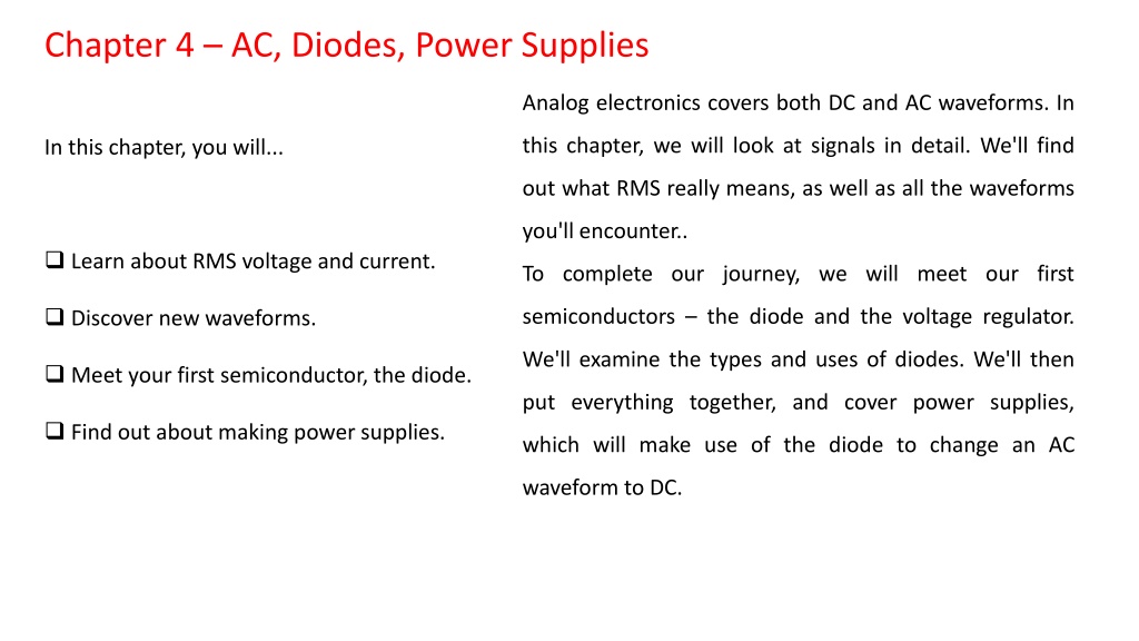
This chapter delves into the intricacies of AC and DC waveforms, exploring RMS voltage, diodes, power supplies, and semiconductor devices like voltage regulators. Through graphical analysis and Ohm's Law, the relationship between AC and DC voltages is clarified, enabling the conversion of RMS to peak voltages. Gain insights into power calculations in AC circuits and learn how diodes play a crucial role in converting AC to DC for efficient power delivery.

Download Presentation

Please find below an Image/Link to download the presentation.
The content on the website is provided AS IS for your information and personal use only. It may not be sold, licensed, or shared on other websites without obtaining consent from the author. Download presentation by click this link. If you encounter any issues during the download, it is possible that the publisher has removed the file from their server.
E N D
Presentation Transcript
Chapter 4 AC, Diodes, Power Supplies Analog electronics covers both DC and AC waveforms. In this chapter, we will look at signals in detail. We'll find In this chapter, you will... out what RMS really means, as well as all the waveforms you'll encounter.. Learn about RMS voltage and current. To complete our journey, we will meet our first Discover new waveforms. semiconductors the diode and the voltage regulator. We'll examine the types and uses of diodes. We'll then Meet your first semiconductor, the diode. put everything together, and cover power supplies, Find out about making power supplies. which will make use of the diode to change an AC waveform to DC.
Chapter 4.1: AC RMS Voltage The Real Story It was mentioned in the last chapter that AC voltages are usually measured in RMS, or root-mean square volts, and this is actually lower than the peak voltage of an AC sinusoid. Now we will discuss the reasoning for this initially confusing standard by deriving this relationship in terms of power delivery. We will not be using calculus, but we can arm ourselves with a little graphical analysis first. What we want to find is a way to relate the AC voltage to a steady-state DC voltage that will have the same heating effect in the load resistance, which will coincide with the same power dissipated by the load resistance over time. This way, all of our power calculations will be correct, as with DC circuits. So there is some scaling factor by which we can scaleback the applied AC voltage to something that makes sense from a power delivery standpoint.
We may employ some simple tricks to help us in our derivation. Take a look below at Figure 4.1. Here, we have a purely resistive load, so voltage and current are always in phase. That is, when voltage is positive (red,) current is positive (orange,) and when voltage is negative, current is also negative. The waveforms trackalong together in time. Though we have a voltage and current that are periodically changing direction, the power dissipated by the load resistance (purple) is always positive, though fluctuating. We also note that the average of the power delivered is half the total height (purple dashed line.) So visually, the average power is half the peak instantaneous power.
We begin by noting, qualitatively, that the average power is half the peak instantaneous power, and by setting this equal to an expression in terms of the effective DC voltage
We can use Ohm's Law now to deal with RMS voltages and currents just as we could in the realm of DC, and the power calculations will make sense as well. We have just uncovered two very useful expressions, which can help us easily convert from an AC RMS voltage to the peak voltage, and from the peak value of an AC voltage to AC RMS volts.
We found in the previous chapter that these equations are needed to design DC power supplies, because the rectified DC voltage will be higher than we might expect if we knew nothing about the difference between AC peak voltage and AC RMS voltage. Rectification means forcing all parts of the waveform to be positive, or flippingover the negative half of the waveform. Chapter 4.2: Amplitude, Frequency, and Phase All periodic waveforms have measurements that are of importance in electronics. Musically, we can describe a note by its pitch and how loud it is. In electronics, there are similar concepts. These are frequency and amplitude. Take a look at Figure 4.2. From the figure, amplitude is the measure of howbig or howloud the signal is. Think of ocean tides. At low tide, the ocean waves are smaller in amplitude, and at high tide, the ocean waves are much bigger in amplitude. Frequency, on the other hand, tells us how fast the signal is oscillating, or how fast it is changing with respect to time.
A slow wave will have a lower frequency, while a fast wave will have a higher frequency. Think of low frequencies as low pitches on a piano, and high frequencies as the really high pitches on a piano. There is a simple connection between frequency and period. Period is the time it takes to complete one full cycle (one full up and down motion,) represented by a capital T, and is measured in seconds
Phase, on the other hand, is a different measurement. Phase is only valid for two signals of the same frequency. The amplitudes can be different, but the frequencies must be the same to make mathematical sense. Phase is measured in degrees or radians, and has to do with how much one signal is leading or lagging behind another one in time. We may think of two clocks; one with the current time, and one that is set five minutes fast. Let's look at this analogy in Figure 4.3.
From the diagram, we see that ClockB is five minutes faster than the current time, represented by Clock A. If we plot the vertical motion of the minute hands of the clocks, we get the figure shown to the right. Clock B, represented by the blue trace, is five minutes faster than Clock A, represented by the red trace. Both minute hands are moving at the same speed one revolution around the clock perhour. But Clock B will always be leading Clock A by five minutes. This relationship is called a phase difference or a phase shift. We measure the phase shift in degrees or radians. For example, if there are 360 degrees in a clock face, then five minutes would correspond to an angle of 30 degrees. Therefore, Clock B has a leading phase of 30 degrees. We may also say that Clock A has a phase lag of 30 degrees with respect to Clock B. We'll cover phase in detail later.
Chapter 4.3: Other Waveforms When we say the words alternatingcurrent, we are actually referring to a much wider category of signals than just pure sinusoids. There are quite a few waveforms used in electronics that are so common that they have been given special names. Let's take a look at a few of them.
In Figure 4.4, shown above, we have eight example waveforms that are discussed frequently in electronics. The sine wave (dark blue) is the one you will most commonly come across. Proceeding from left to right, we have a square wave (red.) Square waves are often found in digital electronics circuits. Most TTL oscillators output this type of waveform. Next, we have a triangle wave (green,) and two ramp waves (orange, and purple.) These types of signals are used for motor positioning, and some systems will report position information this way. Next we have noise (light blue.) This type of signal will be seen in voice, music, or in nature. Noise is a combination of many signals of different frequencies and amplitudes. Noise can be extremely useful as an input to a filter to see what frequencies upon which the filter is acting. The next waveform is the pulse waveform (gray.) Pulses are used for timing, and some sensors may output this type of signal, such as an RPM gauge. Finally, we have a PWM waveform (light green.) PWM, or pulse-width modulation, is used to control power to a load without using resistors to reduce voltage or current. LED drivers use a waveform like this one to control brightness due to the higher efficiency of power delivery
Chapter 4.4 The Diode and DC Power Supplies Diode Construction Diodes are semiconductor devices that are made from silicon or germanium, which are doped with various elements like arsenic and boron to create PN junctions. A PN junction consists of a semiconductor doped with charge donors (N-type semiconductor) in contact with a semiconductor doped with charge acceptors (P-type semiconductor.) The result is that a special junction is created which admits current flow in one direction, but blocks it in the other direction! Let's look at Figure 4.5
In a P-type semiconductor there are mobile holes, and in an N-type semiconductor, there are free electrons. These are collectively referred to as charge carriers. In diodes, the positive terminal is called the anode, and the negative terminal is called the cathode. Current flows in the forward direction, from anode to cathode. The electrons move towards the anode to combine with available holes, and holes move towards the cathode. (These holes don't really move, but the electrons occupying them do move in the direction of the positive terminal, so the holes appear to propagate in he opposite direction.) The real story happens where the charge carriers meet at the junction. In the above diagram, there is a region defined by a gray area where the P-type and N-type semiconductor meet. This is called the depletion region (because there are fewer charge carriers here.) When the diode has no applied voltage, some of the electrons from the N-type semiconductor jump across to the P-type semiconductor to occupy free holes. As more and more electrons do this, the depletion region becomes wider, so the electrons find it harder and harder to jump across the gap. When this depletion region becomes large enough, the electrons cannot make it across the gap to fill the holes on the other side.
When the diode is forward biased, more charge carriers are introduced, and the depletion region becomes smaller. Since the electrons can make it across this gap easily, current is allowed to flow. However, if the diode is reverse biased, the depletion region becomes wider since charge carriers are removed. Therefore, very little current can flow in the reverse direction. Due to the quantum effects in the semiconductor crystal, the diode will drop a small voltage in the forward direction. This voltage is usually about 0.7 V for silicon diodes, and about 0.3 V for germanium. Types of Diodes Since diodes can block current flow in one direction, but allow it to flow in another direction, diodes can be used to rectify an AC voltage. Diodes specially made for this purpose are called rectifier diodes. Some diodes have the unique property of dropping a very steady voltage when they are reverse biased.
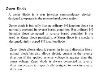
These are called zener diodes, and can be used in power supplies to carefully control DC voltage. This process is called voltage regulation. And signal diodes or switching diodes are used in radio circuits because they are extremely fast. Because diodes drop a small voltage in the forward direction, they dissipate a small amount of heat. They also have limits to the amount of reverse voltage they can stand off before failing. Therefore, diodes are rated for PIV, or peak-inverse-voltage and for their current capacity. Figure 4.6 shows some common diode packages.
Diode Rectification and Power Supply Design Suppose you are building a power supply and have purchased a transformer. It outputs 12 VAC (RMS) on the secondary, but how do you convert AC to DC? Take a look at Figure 4.7, below. On the left, we have an unrectified AC sine wave. Notice that the voltage swings up and down through the zero axis. Suppose we had a switch that automatically opened the circuit when the voltage went negative, giving us the waveform on the right. That is precisely what a diode does. Let's take a look at a simple circuit in Figure 4.8, called a half-wave rectifier, which can accomplish just that.
We have a drawing showing the same circuit for different parts of the applied waveform, showing the diode's conducting and blocking action. Because the diode D1 only conducts in the forward direction, the output voltage across RL, is always positive. Current increases in the load with increasing voltage up to the peak voltage, and then decreases to zero. During the negative half- cycle, the diode is reverse-biased and drops all of the negative voltage, meaning no current flows and the diode's resistance is essentially infinite. An ideal diode is shown for clarity (an ideal diode does not have a forward voltage drop, and reverse current is zero.)
The above circuit is fine if we can live with the gaps in voltage, but it doesn't look like the smooth, constant DC we would expect from, say, a battery. We need to improve the above situation by reducing the gaps in the voltage delivered to the load. If only we could flip over the negative half cycles to reduce those gaps! It turns out there is a circuit that can do just that. But we need a special configuration of diodes called a full-wave bridge rectifier. Figure 4.9 shows a full-wave bridge rectifier.
The diamond of diodes is a bridge rectifier composed of 1N4007 rectifier diodes. During conduction, only two diodes are forward biased at a time. Each pair of diodes takes turn in conducting, one for the positive half- cycle, the other for the negative. This way, no matter what the polarity of the applied voltage, the diodes will force the output to always be in one direction. Therefore, we flip over the negative half-cycles and force them to be positive as well! We have filled in the gaps, which is an improvement over the half-wave rectifier from before. However, the output voltage is still bumpy. The frequency of the bumps will depend on what AC frequency drives the transformer (60 Hz in the United States.) We can smooth the bumps out with a low pass RC filter.
If we use a low pass RC filter on the output, as in Figure 4.10, we get a reasonably good power supply. The series resistor is a low-value, high wattage resistor that suppresses the large current inrush caused by the large capacitor, and contributes to a low RC time constant (we want a low-pass filter with a cutoff below 60 Hz.) There will be a slight ripple on the output, depending on the load.
Voltage Regulation You may be wondering about the square marked LM7805 in Figure 4.10. The low pass RC filter definitely smooths things out for our example power supply. But there is still a slight ripple voltage, which is especially noticeable when we have a load. In order to smooth out the ripple voltage in the power supply, we need what is called a voltage regulator. A voltage regulator can maintain a very stable voltage, even with changes in the input voltage such as a ripple or hum. Before looking at voltage regulator ICs (integrated circuits,) we are going to cover zener diodes first. We may regulate voltage with a simple zener circuit. Recall that if we reverse-bias a zener diode, it will drop a very stable, precise voltage. This is due to a special condition called avalanche mode. These diodes are designed to operate this way, and due to quantum effects, they drop a very precise, constant voltage. Figure 4.11 shows how to use a zener diode. As long as some small current flows through the zener, it will maintain a steady zener voltage across the load. The total current branches off through the diode and through the load. This type of regulator is called a shunt regulator
There's a problem with this circuit. Can you see it? When we disconnect the load resistor, where does the total current flow? It flows through the diode...all of it. This circuit is impractical because if we disconnect the load, we risk burning up the diode. Why? Suppose we have one amp of current, and a 10 V zener diode providing regulation to the load, and the load suddenly disappears. Since the zener diode will take all that current, it will dissipate 10 V * 1 A, or 10 W! Holy cats! That diode is going to be hot! So zeners are fine as a voltage reference, but not so good for power supplies
Voltage Regulator ICs We could use a shunt regulator for our power supply, but it wouldn't be practical. We need a magical device that can provide regulation, but not just burn power away while we have no load connected. The LM78XX and LM79XX series of IC regulators is the answer. The LM78XX series of regulators arepositive regulators, and the LM79XX series are negative regulators. So if we construct a power supply with positive and negative voltages available, these are the devices that can regulate output voltage for our outputs. The last two digits on the package conveniently tell us the regulated output voltage forthe device. For example, an LM7805 is a +5 VDC regulator. An LM7912 is a -12 VDC regulator. Common voltage regulators are shown in Figure 4.12
The TO-220 package is the most common in use. They are one ampere devices that have a tab for attaching to a heatsink. The tab is usually grounded, and physically attached to pin 2. The unregulated voltage goes on pin 1, and the output is taken on pin 3. These regulators need ~2 VDC of overhead. For example, if you want +5 VDC output, they need at least +7 VDC input.