Understanding Special Purpose Diodes in Basic Electronics
Explore the functionalities of zener diodes, varactor diodes, LEDs, quantum dots, and photodiodes in electronic circuits. Discover the characteristics, operations, and applications of these special purpose diodes, including voltage regulation, light emission, and light detection.

Download Presentation

Please find below an Image/Link to download the presentation.
The content on the website is provided AS IS for your information and personal use only. It may not be sold, licensed, or shared on other websites without obtaining consent from the author. Download presentation by click this link. If you encounter any issues during the download, it is possible that the publisher has removed the file from their server.
E N D
Presentation Transcript
Basic Electronics Chapter 3: Special Purpose Diodes 3 1 The Zener Diode 3 2 Zener Diode Applications 3 3 The Varactor Diode 3 4 Optical Diodes
Describe the characteristics of a zener diode and analyze its operation Apply a zener diode in voltage regulation Describe the varactor diode characteristic and analyze its operation Discuss the characteristics, operation, and applications of LEDs, quantum dots, and photodiodes
Zener diode Zener breakdown Varactor Light-emitting diode (LED) Photodiode
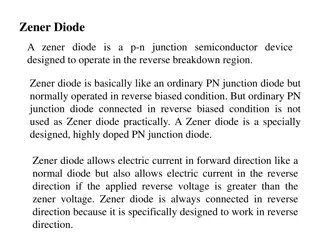
31 THE ZENER DIODE A zener diode is a silicon pn junction device that is designed for operation in the reverse-breakdown region A major application for zener diodes is as a type of voltage regulator for providing stable reference voltages for use in power supplies, voltmeters, and other instruments.
Zener Breakdown Zener diodes are designed to operate in reverse breakdown. Two types of reverse breakdown in a zener diode are avalanche and zener. The avalanche effect occurs in both rectifier and zener diodes at a sufficiently high reverse voltage. Zener breakdown occurs in a zener diode at low reverse voltages. A zener diode is heavily doped to reduce the breakdown voltage. This causes a very thin depletion region.
Zener Equivalent Circuits Figure 3 4 shows the ideal model (first approximation) of a zener diode in reverse breakdown and its ideal characteristic curve. It has a constant voltage drop equal to the nominal zener voltage. This constant voltage drop across the zener diode produced by reverse breakdown is represented by a dc voltage symbol even though the zener diode does not produce a voltage.
Figure 35(a) represents the practical model (second approximation) of a zener diode, where the zener impedance (resistance), ZZ, is included.
Temperature Coefficient The temperature coefficient specifies the percent change in zener voltage for each degree Celsius change in temperature where VZ is the nominal zener voltage at the reference temperature,TC is the temperature coefficient, and is the change in temperature from the reference temperature. A positive TC means that the zener voltage increases with an increase in temperature or decreases with a decrease in temperature. A negative TC means that the zener voltage decreases with an increase in temperature or increases with a decrease in temperature.
Zener Power Dissipation and Derating Zener diodes are specified to operate at a maximum power called the maximum dc power dissipation, PD(max). PD = VZ x IZ Power Derating :The maximum power dissipation of a zener diode is typically specified for temperatures at or below a certain value . Above the specified temperature, the maximum power dissipation is reduced according to a derating factor. The derating factor is expressed in The maximum derated power can be determined with the following formula:
32 ZENER DIODE APPLICATIONS Zener Regulation with a Variable Input Voltage


 represents the practical model (second")
 represents the practical model (second")