Understanding Diode Applications in Modern Electronic Systems

Diodes are essential semiconductor components with various applications in electronic systems. They allow current flow in one direction, serving as one-way switches. Diodes are used in communication systems, computers, power supplies, televisions, radar circuits, and more. One significant application is rectifying AC power to DC power using different rectifier circuits. This process results in pulsating DC output, typically smoothed using capacitors for steady currents. Explore diode operations and applications in different circuits for efficient functioning in electronic systems.

Download Presentation

Please find below an Image/Link to download the presentation.
The content on the website is provided AS IS for your information and personal use only. It may not be sold, licensed, or shared on other websites without obtaining consent from the author. Download presentation by click this link. If you encounter any issues during the download, it is possible that the publisher has removed the file from their server.
E N D
Presentation Transcript
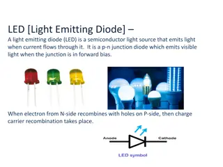
Diode Applications As a simplest semiconductor component, diode has a wide variety of applications in modern electronic systems. Various electronic and electrical circuits use this component as an essential device to produce the required outcome. Diode allows the current flow only in one direction hence acts as a one-way switch. This device can be operated by controlling the voltage applied to it. When the voltage applied to the anode is positive with respect to the cathode (as shown in the figure (a)), the diode is forward biased. If the voltage applied to the diode is greater than the threshold level (potential barrier), which it approx. 0.7 volts for silicon and 0.3 volts for germanium), then diode acts as a short circuit and allows the current flow. If the polarity of the voltage is changed (as shown in the figure (b)), that means cathode is made positive with respect to anode, then it is reverse-biased and acts as open circuit results no current to flow.
The application areas of diodes Communication systems : as limiters and clippers Computer systems : as logic gates and clampers Power supply systems : as rectifiers and inverters Television systems : as phase detectors, limiters and clampers Radar circuits : as gain control circuits Parameter amplifiers
Diode as a Rectifier The most common and important application of a diode is the rectification of AC power to DC power. By using the diodes, we can construct different types of rectifier circuits. The basic types of these rectifier circuits are : 1- Half wave. 2- Full wave center tapped. 3- Full bridge rectifiers.
The following figure shows diode operation as a rectifier : During the positive half cycle of the input supply, anode is made positive with respect to cathode so the diode gets forward biased. These results to flow a current to the load, and the load current flow is proportional to the voltage applied. During the negative half-cycle of the input sinusoidal wave, anode is made negative with respect to cathode so the diode gets reverse-biased. Hence, no current flows to the load. The circuit becomes open circuit and no voltage appears across the load.
Both voltage and current at the load side are of one polarity, that means the output voltage is pulsating DC. Very often this rectification circuit has a capacitor that is connected across the load to produce steady and continuous DC currents without any ripples.
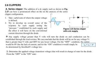
Diodes in Clipping Circuits Clipping circuits are used in FM transmitters where noise peaks are limited to a particular value so that excessive peaks are removed from them. The clipper circuit is used to put off the voltage beyond the preset value without disturbing the remaining part of the input waveform. Based on the diode configuration in the circuit, these clippers are divided into two types; series and shunt clipper. By using these clipper circuits, positive half cycles of the input voltage waveform will be removed. In positive series clipper, during the positive cycle of the input, the diode is reverse-biased so the voltage at the output is zero. Hence the positive half- cycle is clipped off at the output. During the negative half cycle of the input, the diode is forward-biased and the negative half cycle appears across the output.
Diodes in Voltage Multiplier Circuits Voltage multiplier consist of two or more diode rectifier circuits which are cascaded to produce a DC output voltage equal to the multiplier of the applied input voltage. These multiplier circuits are of different types like voltage doubler, tripler, quadrupler, etc. By the usage of diodes combination with capacitors, we get the odd or even multiple of the input peak voltage at the output.
Half-wave Voltage Doubler The figure shows a half-wave voltage doubler circuit whose DC output voltage is twice that of peak inputAC voltage. During the positive half-cycle of the AC input, diode D1 is forward- biased and D2 is reverse-biased. So the capacitor C1 charges up to peak voltage Vmof the input through the diode D1.
During the negative half-cycle of the AC input, D1 is reverse-biased and D2 is forward-biased. So, capacitor C2 starts charging thorough D2 and C1.Thus, the total voltage across the C2 is equal to the 2Vm. During next positive half-cycle, the diode D2 is reverse-biased so the capacitor C2 will discharge through the load. Likewise by cascading the rectifier circuits we will get the multiple values of input voltage at the output.
Diodes in Clamping Circuits: A clamper circuit is used to shift either positive or negative peak of an input signal to a desired level. This circuit is also called as level shifter or DC restorer. These clamping circuits can be positive or negative depends on the diode configuration. In positive clamping circuit, negative peaks are raised upwards so the negative peaks fall on the zero level. In case of the negative clamping circuit, positive peaks are clamped so that it pushes downwards such that the positive peaks fall on the zero level.
During the positive half-cycle of the input, diode is reverse-biased so the output voltage is equal to the sum of input voltage and capacitor voltage (considering the capacitor is initially charged). During the negative half-cycle of the input, diode is forward-biased and behaves as a closed switch so the capacitor charges to a peak value of the input signal
Diodes in Reverse Current Protection The reverse polarity or current protection is necessary to avoid the damage that occurs due to connecting the battery in a wrong way or reversing the polarities of the DC supply. This accidental connection of supply causes to flow a large amount current thorough the circuit components results to explode them. Therefore, a protective or blocking diode is connected in series with the positive side of the input to avoid the reverse connection problem.
The figure shows the reverse current protection circuit where diode is connected in series with the load at the positive side of the battery supply. In case of the correct polarity connection, diode gets forward-biased and load current flows through it. But, in case of wrong connection, the diode is reverse-biased and that doesn t allow any current to flow to the load. Hence, the load is protected against the reverse current.
Diodes in Solar Panels: The diodes which are used for protection of solar panels are called as bypass diodes. If the solar panel is faulty , damaged or shaded by fallen leaves, snow and other obstructions, the overall output power decreases and arise hot spot damage because the current of the rest cells must flow through this faulty or shaded cell causes a overheating. The main function of the bypass diode is to protect the solar cells against this hot spot heating problem.
The following figure shows the connection of bypass diodes in solar cells. These diodes are connected in parallel with the solar cells. Thereby limits the voltage across the bad solar cell and allows the current from good solar cells to the external circuit. Thus, reduces the overheating problem by limiting the current flow through the bad solar cell.
End End