Understanding Zener Diodes for Voltage Regulation
Zener diodes are special diodes designed to have a low reverse breakdown voltage, making them ideal for voltage regulation purposes. When biased in the reverse direction, they provide a stable voltage output regardless of changes in current. This property can be effectively utilized to stabilize voltage sources against variations in supply or load. Explore the unique characteristics and applications of Zener diodes in this informative guide by Dr. Femi Onibonoje.
Download Presentation

Please find below an Image/Link to download the presentation.
The content on the website is provided AS IS for your information and personal use only. It may not be sold, licensed, or shared on other websites without obtaining consent from the author. Download presentation by click this link. If you encounter any issues during the download, it is possible that the publisher has removed the file from their server.
E N D
Presentation Transcript
ENG 222 VOLTAGE REGULATION ZENER DIODE Dr. Femi Onibonoje
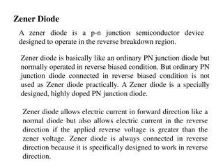
With Signal Diode, the reversebiased diode blocks current in the reverse direction, but will suffer from premature breakdown or damage if the reverse voltage applied across it is too high. However, the Zener Diode or BreakdownDiode as they are sometimes called, are basically the same as the standard PN junction diode but are specially designed to have a low pre-determined Reverse Breakdown Voltage that takes advantage of this high reverse voltage.
The zener diode is the simplest types of voltage regulator and the point at which a zener diode breaks down or conducts is called the Zener Voltage ( Vz ).
The Zener diode is like a general-purpose signal diode consisting of a silicon PN junction. When biased in the forward direction it behaves just like a normal signal diode passing the rated current, but as soon as a reverse voltage applied across the zener diode exceeds the rated voltage of the device, the diodes breakdown voltage is reached at which point a process called Avalanche Breakdown occurs in the semiconductor depletion layer and a current starts to flow through the diode to limit this increase in voltage.
The Zener Diodeis used in its reverse bias or reverse breakdown mode, i.e. the diodes anode connects to the negative supply. From the I-V characteristics curve above, we can see that the zener diode has a region in its reverse bias characteristics of almost a constant negative voltage regardless of the value of the current flowing through the diode and remains nearly constant even with large changes in current as long as the zener diodes current remains between the breakdown current IZ(min) and the maximum current rating IZ(max).
This ability to control itself can be used to great effect to regulate or stabilise a voltage source against supply or load variations. The fact that the voltage across the diode in the breakdown region is almost constant turns out to be an important application of the zener diode as a voltage regulator. The function of a regulator is to provide a constant output voltage to a load connected in parallel with it in spite of the ripples in the supply voltage or the variation in the load current and the zener diode will continue to regulate the voltage until the diodes current falls below the minimum IZ(min) value in the reverse breakdown region.
The resistor, RS is connected in series with the zener diode to limit the current flow through the diode with the voltage source, VS being connected across the combination. The stabilised output voltage Vout is taken from across the zener diode. The zener diode is connected with its cathode terminal connected to the positive rail of the DC supply so it is reverse biased and will be operating in its breakdown condition. Resistor RS is selected so to limit the maximum current flowing in the circuit.
With no load connected to the circuit, the load current will be zero, ( IL= 0 ), and all the circuit current passes through the zener diode which in turn dissipates its maximum power. Also, a small value of the series resistor RS will result in a greater diode current when the load resistance RL is connected and large as this will increase the power dissipation requirement of the diode.
The load is connected in parallel with the zener diode, so the voltage across RL is always the same as the zener voltage, ( VR= VZ)
Zener Diode Example A 5.0V stabilised power supply is required to be produced from a 12V DC power supply input source. The maximum power rating PZ of the zener diode is 2W. Using the zener regulator circuit above calculate: a. The maximum current flowing through the zener diode. b. The minimum value of series resistor RS c. The load current IL if the 1 k is connected across the diode d. The Zener current IZ at full load
a. The maximum current flowing through the Zener diode
