Kookmin University PHY Sub-Proposal for ISC Using CM-FSK Scheme
Kookmin University submitted a PHY sub-proposal for an ISC using a Compatible M-FSK (CM-FSK) scheme to the IEEE P802.15 Working Group for WPANs. The proposal aims to be compatible with rolling shutter image sensors by utilizing the CM-FSK modulation scheme. Design considerations include frame rate variation, different sampling rates and shutter speeds, system architecture, frequency band, data packet structure, and asynchronous decoding. The submission also includes details on an indoor hybrid CM-FSK/N-PSK system and seaside communications using CM-FSK.

Download Presentation

Please find below an Image/Link to download the presentation.
The content on the website is provided AS IS for your information and personal use only. It may not be sold, licensed, or shared on other websites without obtaining consent from the author. Download presentation by click this link. If you encounter any issues during the download, it is possible that the publisher has removed the file from their server.
E N D
Presentation Transcript
doc.: IEEE 802.15-16- 0014 -01-007a January 2016 Project: IEEE P802.15 Working Group for Wireless Personal Area Networks (WPANs) Submission Title: Kookmin University PHY sub-proposal for ISC using a Compatible M-FSK Scheme (CM-FSK) Date Submitted: January 2016 Source: Yeong Min Jang, Trang Nguyen, Hong Chang Hyun [Kookmin University] Contact: +82-2-910-5068 Re: E-Mail: yjang@kookmin.ac.kr Abstract: This is a PHY sub-proposal using M-FSK based Modulation Scheme. Being compatible to rolling shutter image sensors, it is called Compatible M-FSK (CM-FSK). Purpose: Call for Proposal Response Notice: This document has been prepared to assist the IEEE P802.15. It is offered as a basis for discussion and is not binding on the contributing individual(s) or organization(s). The material in this document is subject to change in form and content after further study. The contributor(s) reserve(s) the right to add, amend or withdraw material contained herein. Release: The contributor acknowledges and accepts that this contribution becomes the property of IEEE and may be made publicly available by P802.15. Slide 1 Kookmin University Submission
doc.: IEEE 802.15-16- 0014 -01-007a January 2016 Content PHY design considerations Frame rate variation Different sampling rates and shutter speeds System designs System architecture Frequency band and frequency separation Data packet structure Asynchronous Decoding PHY format and PHY modes Appendix 1: Indoor hybrid Compatible M-FSK/N-PSK system Appendix 2: Seaside communications using CM-FSK Slide 2 Kookmin University Submission
doc.: IEEE 802.15-16- 0014 -01-007a January 2016 PHY design considerations for Compatible M-FSK (CM-FSK) Slide 3 Kookmin University Submission
doc.: IEEE 802.15-16- 0014 -01-007a January 2016 Compatibility to varying-frame-rates Symbol clock out symbol i symbol (i+1) Rolling camera sampling Transform frequency symbol i frequency symbol i/(i+1) frequency symbol i frequency symbol (i+1) frequency symbol (i+1) Majority voting symbol (i+1) voting symbol i voting How to transmit the clock information along with the symbol? Slide 4 Kookmin University Submission
doc.: IEEE 802.15-16- 0014 -01-007a January 2016 Different sampling rates/shutter speeds Camera cut- In-band Eye cut-off Camera shutter speed off ~8 kHz ~200 Hz Bandwidth =? (shutter speed) Camera cut-off In-band Frequency separation =? (sampling rate) Eye cut-off lower shutter speed ~200 Hz The frequency band in use is upper limited by shutter speed of camera. Lower shutter speed narrows the available band for communications Sampling rate (rolling sampling rate) is also a matter to utilize the usage of frequency band efficiently. E.g. the sampling rate defines the minimum value of frequency separation. Slide 5 Kookmin University Submission
doc.: IEEE 802.15-16- 0014 -01-007a January 2016 CM-FSK for ISC Slide 6 Kookmin University Submission
doc.: IEEE 802.15-16- 0014 -01-007a January 2016 System Architecture Transmitter side Receiver side clock information (of a data packet): This scheme is similar to the C-OOK scheme in which asynchronous bits (Ab) represent the form of clock information. However, the data packet with clock information (called a symbol) is encoded using M-FSK technique. a data packet with the clock information Clock information Ab = 1 data packet i Ab=1 Merger Symbol clock Clock information Ab= 0 M-FSK Encoder data packet i a frequency symbol i Slide 7 Kookmin University Submission
doc.: IEEE 802.15-16- 0014 -01-007a January 2016 CM-FSK Modulation frequency band Camera cut-off In-band Eye cut-off Camera shutter speed ~8 kHz ~200 Hz Frequency band Compatibility [200Hz ; ~2 kHz] Webcams, Smartphone cameras (Auto-exposure is OFF) [200Hz ; ~4 kHz] Smartphone cameras (Auto-exposure is OFF) The frequency band: B = 2kHz to be compatible to low shutter speed cameras B = 4kHz (or higher, up to < 8kHz) to be compatible to most of smartphone cameras. Slide 8 Kookmin University Submission
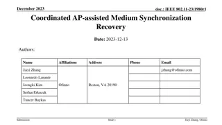
doc.: IEEE 802.15-16- 0014 -01-007a January 2016 CM-FSK frequency separation Selected image resolution: 640x480 FFT peak 120 FFT peak 100 FFT spectrum peak Linear (FFT peak) 80 60 40 20 0 0 500 1000 1500 2000 2500 3000 3500 4000 Lighting frequency (Hz) Spectrum peak and the corresponding frequency measurement The peak value of the FFT spectrum is linear proportional to the modulation frequency of light In our specific experiment Center frequency values: Frequency separation: (FFT peak) 1 <=> (frequency) 32.192 Hz ? = 32.192 ??????? ???????? ???? 15.323 ??? Slide 9 Kookmin University Submission
doc.: IEEE 802.15-16- 0014 -01-007a January 2016 Frequency separation (FFT peak) =3 4??? 96.576??= 41 [channels] Max (number of channel)= FDM spectrum with frequency separation = 96.576 Hz (FFT peak) =1 4??? 32.192 ??= 124 [channels] Max (number of channel) = FDM spectrum with frequency separation = 32.192 Hz Slide 10 Kookmin University Submission
doc.: IEEE 802.15-16- 0014 -01-007a January 2016 Data packet Structure and Encoding Slide 11 Kookmin University Submission
doc.: IEEE 802.15-16- 0014 -01-007a January 2016 Data packet structure Time Domain frequency symbol (i-1) frequency symbol (i+1) frequency symbol i DS i (1) DS i (2) DS i (N) Information of a symbol before encoding Data packet i Ab DS: Data Sub-Packet; SF: Start Packet-Frame Symbol; Ab: Asynchronous bit(s) A symbol is N times repeated in transmission An asynchronous bit (represents the clock information of the data packet) is along with the packet in transmission. Slide 12 Kookmin University Submission
doc.: IEEE 802.15-16- 0014 -01-007a January 2016 Encoding PHY modes (SHR and PHR) best compatible band f'SF extended band fSF Camera limit . . . . . . ~8 kHz 32 frequency SHR and PHR design: On the lowest-band among the CM-FSK PHY modes to ensure compatibility with low sampling-rate cameras. Relationship between fSF and f SF is for training fSF is chosen as lowest frequency on the available bandwidth, e.g. 200Hz, to be easily detected. f SF = fSF + 33x f to train different cameras which have different sampling rates. Slide 13 Kookmin University Submission
doc.: IEEE 802.15-16- 0014 -01-007a January 2016 Encoding PHY modes 2 2 symbols: PSDU length HCS MCS ID SHR Reserved C32-FSK Data frequency: Preamble frequency: fi = fSF + i. f f SF = fSF + 33. f (i=1; 2; ; 32) PHY modes Number of frequency Data rate Unit I.2/ I.3 32 50 bps I.4/ I..5 64 128 60 70 Reserved Slide 14 Kookmin University Submission
doc.: IEEE 802.15-16- 0014 -01-007a January 2016 Encoding table (C32-FSK) C32-FSK encoding table Baud symbol fSF 00000 Frequency Symbol structure fo bits: 1 4 f1 Data packet Ab 00001 f2 . . . f = 96.576 Hz (~ 100Hz) B = [200Hz; 3400Hz] 11110 f31 f32 f33 11111 f'SF Data frequency: (i=1; 2; ; 32) Preamble frequency: fi = fSF + i. f f SF = fSF + 33. f Symbol rate: 5/10/15 (symbol/sec) Slide 15 Kookmin University Submission
doc.: IEEE 802.15-16- 0014 -01-007a January 2016 Encoding table (C64-FSK) C64-FSK encoding table Baud symbol Frequency Symbol structure fSF fo bits: 1 5 000000 f1 Data packet Ab 000001 f2 . . . 101110 f31 f = 48.3 Hz (~ 50Hz) B = [200Hz; 3500Hz] 101111 f32 f'SF f33 010000 f34 Data frequency: (i=1; 2; ; 32; 34;35; ; 65) Preamble frequency: fi = fSF + i. f 010001 f35 f SF = fSF + 33. f . . . 111110 f64 111111 f65 Symbol rate: 5/10/15 (symbol/sec) Slide 16 Kookmin University Submission
doc.: IEEE 802.15-16- 0014 -01-007a January 2016 Asynchronous Decoding Slide 17 Kookmin University Submission
doc.: IEEE 802.15-16- 0014 -01-007a January 2016 Asynchronous Decoding example Ab=1 Ab=1 Symbol out Ab=0 Image frame sequence Decoded symbol along with Ab(s) 1-1110 1-0100 1-1110 1-0100 0-0011 0-0001 0-0011 Ab =1 Ab=0 Ab=1 Group to vote Majority voting result 1110 0100 0011 CM-FSK solves the communications performance, and the asynchronous bits solve the frame rate variation. Slide 18 Kookmin University Submission
doc.: IEEE 802.15-16- 0014 -01-007a January 2016 PHY frame format Slide 19 Kookmin University Submission
doc.: IEEE 802.15-16- 0014 -01-007a January 2016 Best Compatible Band Extended band Camera Physical limit Camera Physical limit CM-FSK (extended band) CM-FSK scheme (on the compatible-band) PSDU length SHR symbol 1 SHR symbol 2 PSDU HCS MCS ID Reserved fSF f SF SHR PHR SHR and PHR design: This part should have compatibility to almost of rolling shutter cameras CM-FSK is chosen because of its advantages of lower error rate compared to OOK: Hence CM-FSK is more reliable in detection and synchronization The frequency band for encoding SHR and PHR is the lowest band among proposed frequency bands to ensure the compatibility to any rolling shutter camera. The PSDU (can keep CM-FSK scheme or switch to C-OOK scheme) is performed on extended band to achieve higher link rate in specific situations. Slide 20 Kookmin University Submission
doc.: IEEE 802.15-16- 0014 -01-007a January 2016 CM-FSK PHY modes PHY header design: All frequencies used for PHY header are on low- band of the available bandwidth (e.g. 200Hz 3.5kHz). This is to be compatible to low sampling rate cameras. SHR and PHR are allocated in a common band (low-band) The length for each frequency symbol is constant throughout the frame between preamble, header, and payload PSDU can be allocated to the extended band. MCS indication PHY modes Data rate Unit bps 0000 0001 I.2 (C32-FSK) 50 0000 0010 I.3 (C32-FSK/2-PSK) 60 0000 0011 I.4 (C64-FSK/2-PSK) 70 80 0000 0100 I.5(C32-FSK/4-PSK) Slide 21 Kookmin University Submission
doc.: IEEE 802.15-16- 0014 -01-007a January 2016 Appendix 1: Indoor hybrid Compatible M-FSK/M-PSK system Slide 22 Kookmin University Submission
doc.: IEEE 802.15-16- 0014 -01-007a January 2016 CM-FSK LEDs lighting In general way, multiple LEDs are grouped together in communications. This is to provide the brightness for indoor when LEDs seems to be dimmed at 50%. Camera sequentially exposes light row by row. To get the maximum length of a LED on the image, LEDs are hang up along the walking way. Slide 23 Kookmin University Submission
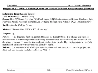
doc.: IEEE 802.15-16- 0014 -01-007a January 2016 L d LED 3 LED 2 LED 1 H FOV Walking Speed = w (m/s) - Condition of LEDs separation in user moving environment: - Longer d is better for communications, but not power consumption. L 2H.tg(FOV/2) Example: H = 2m; FOV = 680 (Samsung S5); d = 1.2m (equal size of fluorescent lamp); L = 2.7m. Walking speed is limited by connection switching algorithm between LEDs. Slide 24 Kookmin University Submission
doc.: IEEE 802.15-16- 0014 -01-007a January 2016 Hybrid Compatible M-FSK/N-PSK: Benefits Advantages of M-FSK: Support for multiple transmitters (LEDs). Frequency allocation is based on M-FSK to share the bandwidth to all LEDs. The M-FSK technique is to avoid interference efficiently. Great support for rolling shutter receivers. The detection of frequency is much easier with rolling effect. Additional advantage of N-PSK: The N-PSK is additionally used to achieve higher data rate than just M-FSK. The higher link rate is helpful when a part of link rate must be shared for mitigating frame rate variation (by transmitting the asynchronous bits instead of data). Additionally support for global shutter receivers (only 2-PSK, optional). Slide 25 Kookmin University Submission
doc.: IEEE 802.15-16- 0014 -01-007a January 2016 Hybrid Compatible M-FSK/2-PSK Data_Phase LED Reference_Phase LED Architecture #1 of LEDs-group transmitter employing the hybrid 2-PSK /CM-FSK modulation scheme. LED 1 and LED 2 together transmit the clock information of data packets through phase (2-PSK technique). The phase difference between LEDs decide the asynchronous bit (bit 1 if two LEDs are same phase; and bit 0 if phases are inverse). This is to solve the frame rate variation. The data packets are transmitted through M-FSK, allowing log2M bits data link rate per symbol. Slide 26 Kookmin University Submission
doc.: IEEE 802.15-16- 0014 -01-007a January 2016 Hybrid Compatible M-FSK/2-PSK 2-PSK Modulation Architecture #2 of LEDs-group transmitter employing the hybrid 2-PSK /M-FSK modulation scheme. In N-PSK scheme, among three LEDs one is for transmitting a phase reference and the other two are for data phases. It means 2 bits are transmitted through 2-PSK. The M-FSK still takes whole advantage of bandwidth without any interference to N-PSK transmission. Slide 27 Kookmin University Submission
doc.: IEEE 802.15-16- 0014 -01-007a January 2016 Data rate of hybrid system Modulation Scheme and Proposed System Data rate 2-PSK and M-FSK combination: (groups of 2-LED tubes) Rbit = (K/2) x logM(#_frequency) x (symbol rate) 1 2-PSK and M-FSK combination: (groups of k-LED tubes) Rbit = (K/k) x logM(#_frequency) x (symbol rate) 2 4-PSK and M-FSK combination: (groups of 4-LED tubes) Rbit = 6 x (K/4) x logM(#_frequency) x (symbol rate) 3 N-PSK and M-FSK combination: (groups of k-LED tubes) Rbit = (k-1)log2N x (K/k) x logM(#_frequency) x (symbol rate) 4 where K: is the number of LED tubes #_frequency: denotes the number of frequencies used for communications in M-FSK Slide 28 Kookmin University Submission
doc.: IEEE 802.15-16- 0014 -01-007a January 2016 Appendix 2: Seaside communications using CM-FSK Slide 29 Kookmin University Submission
doc.: IEEE 802.15-16- 0014 -01-007a January 2016 Prototype Prototype 1: Continuous symbols transmission along with the clock information (asynchronous bits) Symbol structure bits: 1 4/5 symbol 3 symbol 2 symbol 1 Data packet Ab The communications for this prototype is exactly same as mentioned. Prototype 2: Burst mode (with inter-symbol guard time for low-rate PD communications) Symbol structure x Inter-symbol guard time Inter-symbol guard time symbol 3 symbol 2 symbol 1 Data packet The purpose of inter-symbol guard time: A guard time to mitigate frame rate variation, and Also is a period for low-rate PD communications. PD communications is allocated in high band that is invisible to camera (>10 kHz). Purpose of PD communications here: Additional information broadcasting (more data) Localization beacon. ISC provides direction of the lighthouse, while PD communication determines the distance from the lighthouse. Slide 30 Kookmin University Submission
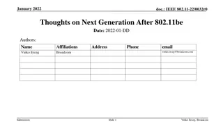
doc.: IEEE 802.15-16- 0014 -01-007a January 2016 Non-Imaging based ISC: An additional optical module In order to collect light energy and distribute uniformly into 2D image sensor, an additional optical lens module is used in front of the camera lens. Incoming beam Rolling shutter camera A type of Fresnel Lens (to collect light energy) Fresnel Lens Lighthouse LED Image Sensor The beam output from Fresnel lens into camera will cover the entire of image sensor instead of focusing into an focal point. Slide 31 Kookmin University Submission