Understanding Resistivity Measurements in Geology
Explore the concept of resistivity measurements in geology, focusing on electrode configurations such as Wenner and Schlumberger arrays. Learn about the potential differences in electrode setups and how to calculate apparent resistivity through geometrical factors. Various electrode arrangements and their significance in subsurface exploration techniques are discussed in detail.

Download Presentation

Please find below an Image/Link to download the presentation.
The content on the website is provided AS IS for your information and personal use only. It may not be sold, licensed, or shared on other websites without obtaining consent from the author. Download presentation by click this link. If you encounter any issues during the download, it is possible that the publisher has removed the file from their server.
E N D
Presentation Transcript
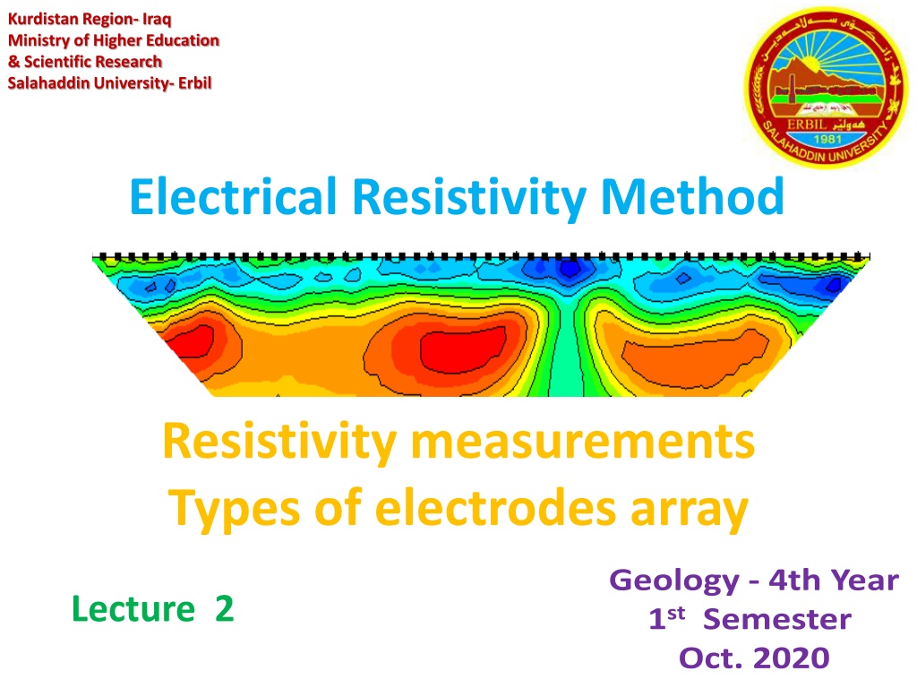
Kurdistan Region- Iraq Ministry of Higher Education & Scientific Research Salahaddin University- Erbil Electrical Resistivity Method Resistivity measurements Types of electrodes array Geology - 4th Year 1stSemester Oct. 2020 Lecture 2
Resistivity measurements Generally, for measuring the resistivities of the subsurface formations, four electrodes namely two current electrodes A and B and two potential electrodes M and N are required. There are different electrode arrangements for measuring the potential difference, which are uniquely used for different purposes in exploration techniques. The most popular among them are Wenner (1915) and Schlumberger (1920).
General case General case The general case is considered, where the current sink is a finite distance from the source. Generalized form of electrode configuration in resistivity surveys.
A M N B
Potential for general case The potential VM at the internal electrode M is the sum of the potential contributions VA and VB from the current source at A and the sink at B. VM = V A + V B The potentials at electrode M and N are: 1 1 i 2 = VM AM MB 1 1 i 2 = VN AN NB
The potential difference 1 1 1 1 i 2 = + V V M N AM MB AN NB and we generally just write the potential difference as: 1 1 1 1 i 2 = + VMN AM MB AN NB or 1 1 1 1 i 2 = + V AM MB AN NB
This equation is easily solved for the resistivity 1 2 1 1 1 1 V = + i AM MB AN NB The term 1 1 1 1 1 + 2 AM MB AN NB Is referred to as a geometrical factor and the apparent resistivity a is often written as:
GV a= i Where G is 1 1 1 1 1 + 2 AM MB AN NB We can see that the geometrical factor contains information about the positioning of the current and potential electrodes in the survey and as you have probably guessed there are several ways to arrange the potential and current electrodes.
Types of electrodes configurations Many electrode configurations are commonly used for ground-surface surveys, such as Schlumberger, Wenner and Dipole-dipole etc, where the electrode separations relate to the investigation depth and the lateral resolution, according to the sensitivity distribution of each arrangement.
Electrode Spread (Array type) C1 P1 P2 C2 1- Wenner Array a a a Surface C1 P1 P2 C2 2- Schlumberger Array r r r Surface C1 C2 P2 P1 na a a Surface 3- Dipole-Dipole Array C1 P1 P2 C2 a na 4- Pole-Dipole Array C1 P1 P2 C2 a 5- Pole-Pole Array
C1 P1 P2 C2 a 6- Gradient Array Surface P0 C1 P1 P2 C2 a a 7- Lee-partition Array a a Surface P2 C2 a a C1 a P1 a 8- Square Array
Electrode configurations: Choice of configuration to use Type of structure to be imaged Sensitivity of configuration to vertical and lateral variations in resistivity Depth of investigation required Resolution required Sensitivity and type of resistivity meter Number of channels Signal strength Background noise level
1- Wenner array In this type the two current electrodes (AB) and the two potential electrodes (MN) are placed in line with each other, In this setup a constant spacing is maintained between the electrodes in the array. That spacing is usually referred to as a. This array is sensitive to horizontal variations. Find the geometric factor?
Advantages of the Wenner type are: 1- Simplicity of the apparent resistivity formula. 2- Relatively small current values are required to produce measurable potential differences. 3- Availability of a large album of theoretical master curves for (two, three, and four) layers earth models
Disadvantages: All electrodes moved each sounding. Sensitive to local shallow variations. Long cables for large depths. Interpretations are limited to simple, horizontally layered structures
2- Schlumberger array The four electrodes are positioned symmetrically along a straight line in the same order AMNB , but with AB 5 MN . To change the depth range of the measurements, the current electrodes are displaced outwards while the potential electrodes in general, are left at the same position. This array is sensitive to vertical variations.
The current electrodes are then expanded, and the resistivity can be given as, ( ) 2 2 / 4 a b V = a b i Determine the geometrical factor of the Schlumberger array?
Advantages of the Schlumberger array over the Wenner array include the following: 1- Need to move the two current electrodes only for most readings. This can significantly decrease the time required to acquire a sounding. 2- Because the potential electrodes remain in fixed locations, the effects of near-surface lateral variations in resistivity are reduced. 3- Sounding curves provide slightly greater probing depth and resolving power than Wenner soundings for equal AB electrode spacing.
3- Dipole-Dipole array The use of the dipole-dipole arrays has become common since the 1950 s , Particularly in Russia. This array type has a better horizontal resolution, but shallower investigation depth than the Wenner array. The apparent resistivity is given by : V = + + ( 1 )( 2 ) an n n a i
4- Pole-Pole array If one of the potential electrodes , N is also at a great distance. V = 2 a a i
5- Pole-Dipole array If only one of the current electrodes is placed at infinity the configuration and the apparent resistivity are as shown: a = 2 a n (n+1) v/i


")