Geodetic Surveying and Triangulation System Overview

Geodetic surveying involves determining precise positions on the Earth's surface, while triangulation is a method that uses interconnected triangles for accurate measurements. The principles of the triangulation system aim to establish horizontal points for various surveys and assist in determining the Earth's size and shape. The classification of triangulation includes primary, secondary, and tertiary orders. Primary triangulation is crucial for providing precise control points and determining the Earth's figure. The primary triangulation process involves meticulous measurements and reductions to ensure accuracy.

Download Presentation

Please find below an Image/Link to download the presentation.
The content on the website is provided AS IS for your information and personal use only. It may not be sold, licensed, or shared on other websites without obtaining consent from the author. Download presentation by click this link. If you encounter any issues during the download, it is possible that the publisher has removed the file from their server.
E N D
Presentation Transcript
MODULE-2 GEODETIC SURVEYING SUBJECT & SUBJECT CODE ADVANCED SURVEYING (17CV46) NAME 0F THE FACULTY: SHASHI PRASAD N DEPT. OF CIVIL ENGG K S SCHOOL OF ENGG & MANAGEMENT
Geodetic Surveying It surveying which is used to determine very precisely the relative or absolute positions on the earth surface of a system of widely separated points. The relative positions are determined in the terms of lengths and azimuths of the line joining them. is defined as the
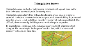
Triangulation It is a system consists of a number of inter connected triangles in which the base line and the angles of the triangles are measured very precisely. With the known length of one side and the three angles, the length of the other two sides of each triangle is computed. The apexes of the triangles is known as triangulation station.
Principles of the triangulation system To provide the most accurate system of the horizontal points on which the less precise triangles may be based, in which in turn may form a framework to which topographical, graphical, engineering and other surveys may be referred. control cadastral, hydro
Principles of the triangulation system To assist in the determination of the size and shape of the earth by making observations latitude, longitude and gravity. for
Classification or order of triangulation system The triangulation system. First order or Primary triangulation. Second order or Secondary triangulation. Third order or Tertiary triangulation following are the classification of
First order or Primary triangulation The first order triangulation is of the highest order and is employed either to determine the earth s figure or to furnish the most precise control points secondary triangulations may be connected. The primary triangulation system embraces the vast area. Every precaution is taken in making the linear and angular measurements and in performing the reductions. to which the
The following are the general specifications of the primary triangulations. Sl.No Particulars Specifications 1. Average triangle closure Less than 1 second. 2. Maximum triangle closure Not more than 3 seconds. 3. Length of the base line 5 to 15 kilometers. 4. Length of the sides of the triangles 30 to 150 kilometers. 5. Actual error of base 1 in 300000. 6. Probable error of base 1 in 1000000 7. Discrepancy between two measures of a section Probable error of the computed distance 10mm 8. 1 in 60000 to 1 in 250000 9. Probable error in astronomic azimuth 0.5 seconds
Second order or Secondary Triangulation It consists of a number of points fixed framework triangulation. The stations are fixed at close intervals so that the sizes of the triangle formed are smaller primary triangulation. The instruments methods used are not of the same utmost refinement. within primary a of than the and
The following are the general specifications of the secondary triangulations. Sl.No Particulars Specifications 1. Average triangle closure 3 seconds 2. Maximum triangle closure 8 seconds 3. Length of the base line 1.5 to 5 kilometers. 4. Length of the sides of the triangles 8 to 65 kilometers. 5. Actual error of base 1 in 150000. 6. Probable error of base 1 in 500000 7. Discrepancy between two measures of a section Probable error of the computed distance Probable error in astronomic azimuth 20mm 8. 1 in 20000 to 1 in 50000 9. 2.0 seconds
Third order or Tertiary triangulation It consists of a number of points fixed within the framework of secondary triangulation, and forms the immediate control for detailed engineering and the other surveys. The size of the triangles is small and instrument with the moderate precision may be used.
Selection of triangulation stations The triangulation stations should be inter visible. For this purpose, they should be placed upon the most elevated ground so that long sights through undisturbed atmosphere may be secured. They should form well shaped triangles. As far as possible, the triangles should neither be isosceles with base angles of about 560 or equilateral. In general, however no angle should be smaller than 300 or greater than 1200. The stations should be easily accessible, and should be such that supplies of food and water are easily available and camping ground or nearest suitable accommodation is available.
Selection of triangulation stations They should be so selected that the length of sight is neither too small nor too large. Small length of sight will result in errors due to centering and bisection while large line of sight will make the signal too indistinct for accurate bisection. They should be in commanding situations, so as to serve as control of the subsidiary triangulations and for possible future extension of the principal system. The stations of the subsidiary triangulations should be such that they are useful for detail surveys. In heavily wooden country, the stations should be so located that the cost of clearing and cutting and of building towers is minimum. The stations should be situated so that lines of sight do not pass over towns, factories, furnaces neither etc. nor graze any obstructions, so that the effects of irregular atmospheric refraction are avoided.
Selection of Base Lines The site should be fairly level. If, however, the ground is sloping, the slope should be uniform and gentle. Undulating ground should, if possible be avoided. The site should be free from obstructions throughout the whole of the length. The line clearing should be cheap in both labour and compensations. The extremities of the base should be intervisible at the ground level. The ground should be reasonably firm and smooth. Water gaps should be few, and if possible not wider than the length of the long wire or tape. The site should suit extension to primary triangulation. This is an important factor since the error in extension is likely to exceed the error in measurements.
Triangulation figures It is defined as a group or system of triangles such that any figures has one side and only one, common to each of the preceding and the following figures. The following considered while selecting a particular figure: The figure should be such that the computations can be done through two independent routes. The figures should be such that at least one and preferably both routes should be well conditioned. All the lines in a figure should be of comparable length. Very long lines should be avoided. The figure should be such that least work may secure maximum progress. Complex figures should not involve more than about twelve conditions. are the factors
Triangulation figures The following are the common figures or systems: Single chain of triangles. Double chain of triangles. Central point of figures. Quadrilaterals.
Single chain of triangles It is used where a narrow strip of terrain is to be covered. Though the system is rapid and economical, it is not so accurate for primary work since the number of conditions to be fulfilled in the figure adjustment is relatively small. Also, it is not possible to carry the solution of triangles through the figures by two routes. If the accumulation of errors is not to be become excessive, base lines must frequently. independent be introduced
Central point of figures It is used to cover area, and give very satisfactory results in flat country. The centered figures may be quadrilateral, hexagons with stations. The system provides the desired checks on the computations. The progress of work is slow due to more settings instrument. pentagons, the or central of the
Quadrilaterals The quadrilateral with four corner stations observed diagonal forms the best figures. They are best suited for hilly country. Since the computed lengths of the sides can be carried through the systems by combinations of sides and angles, the system is the most accurate. and different different
Marking of Stations The mark should be distinctive and indestructible. Two marks should be provided one visible on the surface and the other buried vertically below. The mark may be set on firm rock, or on concrete monument. Two or three reference marks, similar in material and shape to the station mark, should be installed. The distance and bearings of these references marks from the station mark and from each other should be recorded on them. At each station where a tall signal tower is needed, an azimuth mark should be established at some distance away from the station mark. The azimuth mark should be of the same size and character as the reference mark.
Reduction to the centre In order to secure well conditioned triangle or better visibility, objects such as church spires, towers etc. are sometimes selected as the triangulation station. When the observations are to be taken from a station, it is impossible to setup an instrument over it. In such case, a subsidiary station known as satellite station. This stations are selected as near to the main station as possible and observations are taken to the other triangulation stations with the same precision as would have been used in the measurement of angles at the true station. These angles are later corrected and reduced to what they would have been if the true station was occupied. The operation of applying the corrections due to the eccentricity of the station is known as reduction of centre.
REFERENCES https://www.youtube.com/watch?v=ApKw5qWqYF 8 https://www.youtube.com/watch?v=CZ8Hn76vOqU