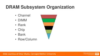
Overview of GPU Architecture and Memory Systems in NVIDIA Tegra X1

Dive into the intricacies of GPU architecture and memory systems with a detailed exploration of the NVIDIA Tegra X1 die photo, instruction fetching mechanisms, SIMT core organization, cache lockup problems, and efficient memory management techniques highlighted in the provided educational materials.
Download Presentation
Please find below an Image/Link to download the presentation.
The content on the website is provided AS IS for your information and personal use only. It may not be sold, licensed, or shared on other websites without obtaining consent from the author. Download presentation by click this link. If you encounter any issues during the download, it is possible that the publisher has removed the file from their server.

Presentation Transcript
/ EECE 571T: Compute Accelerator Architectures Spring 2019 Slide Set #3: GPU Architecture Instructor: Dr. Tor M. Aamodt aamodt@ece.ubc.ca NVIDIA Tegra X1 die photo 1
Quiz #2 15 minutes. Based upon readings assigned last week. 2
Reading for next week Gebhart et al., Energy-efficient mechanisms for managing thread context in throughput processors, ISCA 2011 Liu et al., Get Out of the Valley: Power-Efficient Address Mapping for GPUs, ISCA 2018 3
Learning objectives After we finish this set of slides you should be able to: Describe the microarchitecture of a generic SIMT GPU pipeline similar to those in NVIDIA GPUs. Describe various portions of the memory system microarchitecture found in a GPU. 4
SIMT Front End SIMD Datapath Branch Target PC Fetch SIMT-Stack ALU ALU ALU ALU Valid[1:N] Active Mask Pred. I-Buffer Operand Collector I-Cache Decode Issue Score Board MEM Done (WID) Let s examine details of this organization. Start with Fetch and work way through pipeline. 6
Instruction Fetch Assuming a single port to read instructions from instruction cache how to handle fetch for multiple warps? Arbitrate among warps for access to the instruction cache How to handle cache misses? PC1 PC2 PC3 A R B To I-Cache Selection Valid[1:N] Fetch Valid[1:N] I-Buffer I-Cache Decode 7
Cache Lockup Problem Let s revisit the hardware required to implement a (set associative) cache. To reduce costs: Data and tag arrays have one read port. On a cache miss: 1. Select victim block 2. Evict it from cache 3. Put new block here once it returns from memory How to implement steps? Finite state machine (FSM) is default way to control a datapath circuit. Problem: Can take 100 s of cycles for step 3 to complete. During this time pipeline stalled if using simple FSM. 9
Miss Status Holding Register (MSHR) Kroft, Lockup-free instruction fetch/prefetch cache organization , ISCA 1981. Idea: Enable parallelism in access to memory by using MSHR to record information about requests to memory that have been initiated. Many variations possible in details. If encounter second access to a line that you have requested can potentially avoid sending second request to memory by searching MSHRs. 10
Instruction Fetch If instruction cache miss then no instruction fetched for that warp this cycle. Select PC for a different warp next cycle. Eventually missing cache block will return from memory. Then select this warp again and this time (should) hit. PC1 PC2 PC3 A R B To I-Cache Selection Valid[1:N] Fetch Valid[1:N] I-Buffer I-Cache Decode 11
Fetch and Decode are Coupled The instruction buffer (I- Buffer) holds decoded instructions that are ready to issue to execution units. Cannot fetch next instruction if I-buffer slot for warp is occupied. Fetched instruction is decoded and then stored in the I-Buffer One or more entries / warp. Need more than one entry for superscalar instruction issue. Score- Board Decode PC1 PC2 PC3 A R B v v v Inst. W1 r Inst. W2 Inst. W3 r r To I-Cache Selection To Fetch Issue ARB Issue Valid[1:N] Fetch Valid[1:N] I-Buffer I-Cache Decode 12
Instruction Issue Select a warp and issue an instruction from its I-Buffer for execution How to select which warp to issue? Na ve approach Round Robin among all warps in I-Buffer. As shown in CCWS paper, round robin can be bad for data cache. Greedy-Then-Oldest (GTO) Continue scheduling instructions from a single warp until cannot issue any more. Then switch to oldest warp that has ready instructions. This tends to improve intra warp/wave locality and thus increase hit rates. Score- Board Decode v v v Inst. W1 r Inst. W2 Inst. W3 r r To Fetch Issue ARB Issue 13
Control Hazards in GPUs Branch Target PC Fetch SIMT-Stack ALU ALU ALU ALU Valid[1:N] Active Mask Pred. I-Buffer Operand Collector I-Cache Decode Issue Score Board MEM Done (WID) Which instruction should be fetched after a branch? Branch executed late in pipeline (ALUs) If want more than one instruction from warp in pipeline at once, then need to deal with Control Hazards . 14
Review: Control Hazards Branch may or may not change program counter (PC). Therefore, which instruction should follow a branch depends upon the result of executing the branch instruction. Recall: Result of branch typically known by end of EX (or ID). 15 Text: COD ARM Edition 4.8
Option 1: Stall First, let s define some terminology: Label: BNE Label ; branch instruction ADD R1,R2,R3 ; branch successor for not taken branch LD R1,0(R2) SUB R1,R2,R3 ; branch successor for taken branch 16 Text: COD ARM Edition 4.8
Option 1: Stall Clock Number 4 M F 1 F 2 D 3 X 5 W D F 6 7 8 branch instruction branch successor branch succ. + 1 branch succ. + 2 X D F M X D W M X Decode branch and stall fetch on cycle 2 Fetch successor on cycle 4. (cannot do this on cycle 3) Resolve branch during cycle 3. (hardware determines successor at end of cycle 3) 17 Text: COD ARM Edition 4.8
Option 2: Predict Not Taken (correct prediction) Clock Number 4 M X D F 1 F 2 D F 3 X D F 5 W M X D 6 7 8 Not taken branch branch instr. + 1 branch instr. + 2 branch instr. + 3 W M X W M W Resolve branch during cycle 3. Hardware determines successor at end of cycle 3. In this case, the prediction turns out to be correct since the branch was not taken. We did not know this until end of cycle 3. On cycle 2, hardware predicts next instruction is branch instr. + 1 18 of 30
Option 2: Predict Not Taken (incorrect/wrong prediction) Clock Number 4 M X D F 1 F 2 D F 3 X D F 5 W M X D 6 7 8 TAKEN branch branch instr. +1 branch instr. +2 branch target W M X W M W Next cycle (clock cycle 4), fix incorrect prediction. Two things happen: 1. Squash incorrectly fetched instructions (turn into no ops or bubbles ) 2. Start fetching correct instruction Resolve branch on cycle 3. Find out prediction was wrong.
Control Hazards in GPUs Branch Target PC Fetch SIMT-Stack ALU ALU ALU ALU Valid[1:N] Active Mask Pred. I-Buffer Operand Collector I-Cache Decode Issue Score Board MEM Done (WID) With round robin scheduling it is possible to allow only a single instruction in pipeline at once. If number of warps available is high, and most instructions are not long latency memory access operations, this should be OK. In practice, number of warps can be limited due to high register demand or lack of application parallelism. With GTO scheduling it is essential to enable multiple instructions from same warp into pipeline at once. 20
Instruction Issue: Superscaler How many instructions to issue from warp? GT200 onward: Dual issue (superscalar) Score- Board Decode v v v Inst. W1 r Inst. W2 Inst. W3 r r To Fetch Issue ARB Issue 21
Review: Data Dependences/Hazards hazard hazard hazard Dependence: Property of the program Hazard: Property of pipeline organization 22
Can we do better than pipelining? Loop: ld add sub bne r2, r3, r1, r1, 0(r1) r3, r1, r0, r2 1 loop sum += a[i--] Pipelining: time fetch decode fetch ld decode fetch add decode fetch sub decode bne Superscalar: fetch decode fetch fetch ld decode decode fetch add sub decode bne 23
Dependence Checking tgt src1 src1 Program order tgt src1 src1 tgt src1 src1 Assume 2 source & 1 target max per instr. comparators for 2-way: 3 for tgt and 2 for src (tgt: WAW + WAR, src: RAW) comparators for 4-way: 2nd instr: 3 tgt and 2 src 3rd instr: 6 tgt and 4 src 4th instr: 9 tgt and 6 src 24
Instruction Issue How many instruction schedulers? Fermi and later: 2+ schedulers Score- Board Decode v v v Inst. W1 r Inst. W2 Inst. W3 r r To Fetch Issue ARB Issue 25
Hazards in GPU Pipelines What happens when an instruction encounters a data hazard later in the pipeline? Examples: What happens when a data cache access misses? What happens if encounter a TLB miss and cannot even determine if a cache access was a hit or a miss? Shared memory bank conflicts don t know how many until compute address for each lane. Uncoalesced memory accesses... Don t know how many memory accesses. Score- Board Decode v v v Inst. W1 r Inst. W2 Inst. W3 r r To Fetch Issue ARB Issue 26
Stall Hardware: Hazard Detection Unit NOP Question: What is cost of stalling a GPU pipeline? 27
Hazards in GPU Pipelines To avoid stalling pipeline keep instruction in I-buffer until know it can complete This approach is known as replay. Replay is commonly approach in out of order superscalar CPUs (caused issues in Pentium 4 design). There are oblique references to use of instruction replay in performance counters for NVIDIA GPUs. Advantage: Can potentially reduce area overhead required for buffering. Reduce long wires required to implement stall signals. Score- Board Decode v v v Inst. W1 r Inst. W2 Inst. W3 r r To Fetch Issue ARB Issue 28
Does Replay help Performance? Andrew Turner, On Replay and Hazards in Graphics Processor Units , MASc Thesis 2012. https://open.library.ubc.ca/cIRcle/collections/ ubctheses/24/items/1.0073331 Answer in above study was not much performance gained by using replay. 29
Issue Scoreboard How does hardware know if it can issue next instruction for a given warp? What are the tradeoffs? Score- Board Decode v v v Inst. W1 r Inst. W2 Inst. W3 r r To Fetch Issue ARB Issue 30
+ Review: In-order Scoreboard Scoreboard: a bit-array, 1-bit for each register If the bit is not set: the register has valid data If the bit is set: the register has stale data i.e., some outstanding instruction is going to change it Issue in-order: RD Fn (RS, RT) If SB[RS] or SB[RT] is set RAW, stall If SB[RD] is set WAW, stall Else, dispatch to FU (Fn) and set SB[RD] Complete out-of-order Update GPR[RD], clear SB[RD] Scoreboard Register File 0 Regs[R1] Regs[R2] Regs[R3] 1 0 0 Regs[R31] [Gabriel Loh] 31
+ In-Order Scoreboard for GPUs? Problem 1: 32 warps, each with up to 128 (vector) registers per warp means scoreboard is 4096 bits. Problem 2: Warps waiting in I-buffer needs to have dependency updated every cycle. Solution? Flag instructions with hazards as not ready in I-Buffer so not considered by scheduler Track up to 6 registers per warp (out of 128) I-buffer 6-entry bitvector: 1b per register dependency Lookup source operands, set bitvector in I-buffer. As results written per warp, clear corresponding bit 32
Example + Code ld r7, [r0] mul r6, r2, r5 add r8, r6, r7 Scoreboard Instruction Buffer Index 3 Index 0 Index 1 Index 2 i0 i1 i2 i3 0 0 0 0 0 0 0 0 0 0 0 0 0 0 0 0 0 0 0 0 0 0 0 0 Warp 0 Warp 1 Warp 0 r7 r7 r7 r7 r7 r7 - - r6 r6 r6 - - - - - r8 r8 r8 r8 r8 - - - - - - - - - - - ld r7, [r0] ld r7, [r0] ld r7, [r0] ld r7, [r0] ld r7, [r0] ld r7, [r0] - - - - - - - - - - - - - - - - - - - - - - - - - - - - - - - - mul r6, r2, r5 0 0 0 0 mul r6, r2, r5 0 0 0 0 mul r6, r2, r5 0 0 0 0 add r8, r6, r7 1 1 0 0 add r8, r6, r7 1 1 0 0 add r8, r6, r7 1 0 0 0 add r8, r6, r7 1 0 0 0 add r8, r6, r7 0 0 0 0 Warp 1
Register File 32 warps, 32 threads per warp, 16 x 32-bit registers per thread = 64KB register file. Need 4 ports (e.g., FMA) greatly increase area. Alternative: banked single ported register file. How to avoid bank conflicts? 34
Banked Register File Strawman microarchitecture: Register layout: 35
Register Bank Conflicts warp 0, instruction 2 has two source operands in bank 1: takes two cycles to read. Also, warp 1 instruction 2 is same and is also stalled. Can use warp ID as part of register layout to help. 36
Operand Collector Bank 0 Bank 1 Bank 2 Bank 3 R0 R1 R2 R3 R4 R5 R6 R7 R8 R9 R10 R11 add.s32 R3, R1, R2; No Conflict Conflict at bank 0 mul.s32 R3, R0, R4; Term Operand Collector appears in figure in NVIDIA Fermi Whitepaper Operand Collector Architecture (US Patent: 7834881) Interleave operand fetch from different threads to achieve full utilization 4a.37
Operand Collector (1) Issue instruction to collector unit. Collector unit similar to reservation station in tomasulo s algorithm. Stores source register identifiers. Arbiter selects operand accesses that do not conflict on a given cycle. Arbiter needs to also consider writeback (or need read+write port) 38
Operand Collector (2) Combining swizzling and access scheduling can give up to ~ 2x improvement in throughput 39
GPU Microarchitecture Overview GPU SIMT Core Cluster SIMT Core Cluster SIMT Core Cluster SIMT Core SIMT Core SIMT Core SIMT Core SIMT Core SIMT Core Interconnection Network Memory Partition Memory Partition Memory Partition Off-chip DRAM GDDR3/GDDR5 GDDR3/GDDR5 GDDR3/GDDR5 41
Caches Critical for Performance Reduce average latency Reduce average bandwidth Data is logically transferred from producer to consumer via memory store reg --> mem load reg <-- mem P P P Many processors can share data efficiently Problem: What happens when store & load are executed on different processors? 42
Cache Coherence Problem P2 P1 P3 u = ? 3 u = ? 4 5 $ $ $ u:5 u= 7 u :5 I/O devices 1 2 u:5 Memory Processors see different values for u after event 3 With write back caches, value written back to memory depends on order of which cache writes back value first Unacceptable situation for programmers 43
Cache Coherence Example P2 P1 P3 u = ? 3 u = ? 4 5 $ $ $ u= 7 u:5 u :5 I/O devices 1 2 u:5 u = 7 Memory Must invalidate before step 3 NOTE: This solution e difficult to implement for GPUs (as discussed in paper assigned for today). 44
Level one data cache Some recent NVIDIA GPUs enable you to configure how much shared memory versus L1 cache. See above. Recent GPUs have read-only L1 and will not even cache global memory accesses since global data can be written. Local memory does not have a coherence problem so can be write-back. Pending Request Table is like MSHRs 45
L1 Texture Cache Problem: With small capacity cache all tags might end up being used for blocks that are misses. Solution: Decouple tag array from data array. The tag array contains view of what will eventually be present in the data array after memory accesses complete. Requires that cache fill data is handled in order. This is done using reorder buffer and fragment FIFO. 46
Texture Cache Read-only cache with FIFO retirement Design based on Igehy et al. Prefetching in a Texture Cache Architecture, SIGGRAPH 1998. GPGPU-Sim support 1-D and 2-D textures 2-D locality should be preserved when texture cache blocks are fetched from memory GPGPU-Sim uses a 4-D blocking address scheme to promote spatial locality in 2-D Based on Hakura et al. The Design and Analysis of a Cache Architecture for Texture Mapping, ISCA 1997 47
Memory Partition Memory requests are distributed to different memory partitions using a hash function on memory address. Typically, stride between memory at granularity of 256B although could be other amount. So cache block size could be up to 256B. 48
Last level (L2) cache L1 cache is typically read only to avoid cache coherence problem. L2 cache is physically banked among memory partitions , but logically it acts as a single cache. So, there is no cache coherence problem for global memory accesses. 49
Recall: Coalescing global accesses Not same as CPU write combining/buffering: Aligned accesses request single 128B cache blk 128 255 ld.global r1,0(r2) Memory Divergence: 128 1152 256 1024 ld.global r1,0(r2) 50


")


")
")


 cache")