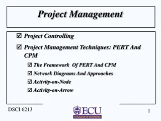
Understanding PERT and CPM Techniques in Project Management

Learn about PERT (Program Evaluation and Review Technique) and CPM (Critical Path Method) techniques used in project management. Discover how these methods help in coordinating activities, developing schedules, and monitoring project progress. Explore the applications of PERT and CPM in various industries and understand the concept of activity types in project planning through network diagram representations.

Download Presentation

Please find below an Image/Link to download the presentation.
The content on the website is provided AS IS for your information and personal use only. It may not be sold, licensed, or shared on other websites without obtaining consent from the author. Download presentation by click this link. If you encounter any issues during the download, it is possible that the publisher has removed the file from their server.
E N D
Presentation Transcript
Introduction One of the most challenging jobs that any manager can take on is the management of a large-scale project that requires coordinating numerous activities throughout the organization. A myriad of details must be considered in planning how to coordinate all these activities, in developing a realistic schedule, and then in monitoring the progress of the project.
Introduction Fortunately, two closely related operations research techniques, PERT (program evaluation and review technique) and CPM (critical path method), are available to assist the project manager in carrying out these responsibilities. These techniques make heavy use of networks to help plan and display the coordination of all the activities. They also normally use a software package to deal with all the data needed to develop schedule information and then to monitor the progress of the project. Project management software, such as MS Project is widely available for these purposes.
Introduction PERT and CPM are basically time-oriented methods in the sense that they both lead to determination of a time schedule for the project. The approaches is that the time estimates for the different activities in CPM were assumed to be deterministic while in PERT these are described probabilistically. These techniques are referred as project scheduling techniques significant difference between two
Applications of CPM / PERT Construction of a dam or a canal system in a region Construction of a building or highway Maintenance or overhaul of airplanes or oil refinery Space flight Cost control of a project using PERT / COST Designing a prototype of a machine Development of supersonic planes
Activity Any resources and has an end and a beginning is called activity. An arrow is commonly used to represent an activity with its head indicating the direction of progress in the project. These are classified into four categories individual operation which utilizes
Types of Activity Predecessor activity Activities that must be completed immediately prior to the start of another activity are called predecessor activities. Successor activity Activities that cannot be started until one or more of other activities are completed but immediately succeed them are called successor activities.
Types of Activity Concurrent activity Activities which can be accomplished concurrently are known as concurrent activities. It may be noted that an activity can be a predecessor or a successor to an event or it may be concurrent with one or more of other activities. 2 1 3 4
Types of Activity Dummy activity An activity which does not consume any kind of resource but merely depicts the technological dependence is called a dummy activity. It is represented by dotted line arrow. It is used only when it is necessary , there is no restriction of no. of dummy activity used. There should be no looping and dangling on network diagram.
Types of Activity The dummy activity is inserted in the network to ESTABLISH THE relationship among the activities of the project. It is needed when (a) two or more parallel activities in a project have same head and tail events (b) two or more activities have some (but not all) of their immediate predecessor activities in common. given precendence
Types of Activity For example, consider a situation where A and B are concurrent activities. C is dependent on A and D is dependent on A and B both. Such a situation can be handled by using a dummy activity as shown in the figure.
no two activities can be identified by the same beginning and end event in such cases a dummy activity is introduced to resolve the problem
Network A network is a graphic representation of a project s operations and a composed of activities and events that must be completed to reach the end objective of a project, showing the planning sequence of time accomplishment, their dependence and inter- relationship. The basic components of a network are
Activity- An activity is a task, or item of work to be done, that consume time, effort, money or other resources. An activity is represented by an arrow with its head indicating the sequence in which the events are to occur.
Event- An event represents the start (beginning) or completion (end) of some activity and as such it consume no time. It has no time duration and does not consume any resources. It is also known as a node. An event is generally represented on the network by a circle.
Event (Milestone) The beginning and end points of an activity are called as event or nodes. event is a point in time and does not consume any resources. It is represented by a number circle. the head even called as jth event always a number higher than the tale event called the ith eventevent 1 2 The events are classified in to three categories
Merge event: When more than one activity comes and joins an event such an event is known as merge event.
Burst event When more than one activity leaves an event such an event is known as burst event
Merge and Burst event An activity may be merge and burst event at the same time as with respect to some activities it can be a merge event and with respect to some other activities it may be a burst event.
The activity can be further classified into the following three categories
Common Errors in Drawing Networks 1. Dangling To disconnect an activity before the completion of all activities in a network diagram is known as dangling. As shown in the figure activities (5 10) and (6 7) are not the last activities in the network. So the diagram is wrong and indicates the error of dangling
Looping or Cycling: Looping error is also known as cycling error in a network diagram. Drawing an endless loop in a network is known as error of looping as shown in the following figure
Redundancy: Unnecessarily inserting the dummy activity in network logic is known as the error of redundancy as shown in the following diagram
Rules for Network Representation Three rules are available for constructing the network 1. Each activity is represented by one, and only one arrow (arc) 2. Each activity must be identified by two distinct end nodes & no two or more activities can have the same tail. 3. To maintain the correct precedence relationships, the following questions must be answered as each is added to network: (a) What activities must immediately precede the current activity? (b) What activities must follow the current activity? (c) What activities must occur concurrently with the current activity? The answer of these questions may require the use of dummy activities to ensure correct precedences among the activities.
Numbering the events- Fulkerson Rule After the network is drawn in a logical sequence, every event is assigned a number. The number sequence must be such as to reflect the flow of the network. In event numbering, the following rules should be observed, which is also known as Fulkerson s rule. (a) Event numbers should be unique (b) Event numbering should be carried out on a sequential basis from left to right (c) The initial event which has all outgoing arrows with no incoming arrow is numbered 0 or 1 (d) The head of an arrow should always bear a number higher than the one assigned at the tail of the arrow (e) Gaps should be left in the sequences of event numbering to accommodate subsequent inclusion of activities, if necessary.
CPM/PERT CPM/PERT designed to assist in the planning, scheduling and control of projects. are network based models Project- A project is defined as a collection of interrelated activities with each activity consuming time and resources
CPM/PERT The objective of CPM/PERT is to provide analytic means for scheduling the activities. Followings are the steps of the techniques
CPM/PERT 1. We define the activities of the project, their precedence relationship and their time requirements. 2. The precedence relationship among the activities are represented by a network 3. Specific computations to develop the time schedule for the project. During the actual execution of the project things may not proceed as planned, as some of the activities may be expedited or delayed. When this happens, the schedule must be revised to reflect the realities on the ground. This is the reason for including a feedback loop between the time schedule phase and the network phase, as shown in following diagram.
CPM/PERT The two techniques, CPM and PERT, which were developed independently, differ in that CPM assumes deterministic activity duration and PERT assumes probabilistic durations.
CPM It is commonly used for those projects which are repetitive in nature & where one has prior experience of handling similar projects. It is a deterministic model and places emphasis on time & cost for activities of a project.
PERT PERT Technique)- it is generally used for those projects where time required to complete various activities are not known as a prior. It is probabilistic model & is primarily concerned for evaluation of time. It is event oriented. (Program evaluation & review
PERT/CPM Advantages A PERT/CPM chart explicitly defines and makes visible dependencies (precedence relationships) between the elements, PERT/CPM facilitates identification of the critical path and makes this visible, PERT/CPM facilitates identification of early start, late start, and slack for each activity, PERT/CPM provides for potentially reduced project Duration due to better understanding of dependencies leading to improved overlapping of activities and tasks where feasible.
PERT/CPM disadvantages There can be potentially hundreds or thousands of activities and individual dependency relationships, The network charts tend to be large and unwieldy requiring several pages to print and requiring special size paper, The lack of a timeframe on most PERT/CPM charts makes it harder to show status although colours can help (e.g., specific colour for completed nodes), When the PERT/CPM charts become unwieldy, they are no longer used to manage the project.
Rules for AOA network construction Following are some of the rules that have to be followed while constructing a network: 1. In network diagram, arrows represent activities and circles the events. The length of an arrow is of no significance.
Rules for AOA network construction Each activity should be represented only by one Arrow and must start and end in a circle called event. The tail of an activity represent the start, and head the completion of work
Rules for AOA network construction The event numbered 1 denote the start of the project and is called initial event. All activities emerging from event 1 should not be preceded by any other activity or activities. an event carrying the highest number denote the completion event. A network should have only one initial event and only one terminal event
Rules for AOA network construction The general rule for numbering the event is that the head even should always be number larger than the number at its tail that is event should be number such that for each activity (I,j), i<j.
Rules for AOA network construction An activity must be uniquely identified by its starting and completion event which implies that An event number should not get repeated or duplicated two activity should not be identified by the same completion event Activities must be represented either by their symbols or by the corresponding ordered pair of starting completion event
Example Draw the logic network for the following: Activities C and D both follow A , activity E follows C , activity F follows D , activity E and F precedes B.
A 1 2
3 C A 1 2 D 4
3 C E A 1 2 5 D F 4
3 C E A B 1 2 5 6 D F 4
Construct a network for a project whose activities and their predecessor relationship are given in table Acti vity A B C D E F G H I J K Pred eces sor - - - A B B C D E H,I F,G
1 1 2 A 2 1 B 2 3 C 4 4


")