Volvo BL61 PLUS Backhoe Loader Service Repair Manual Instant Download
Please open the website below to get the complete manualnn// n

Download Presentation

Please find below an Image/Link to download the presentation.
The content on the website is provided AS IS for your information and personal use only. It may not be sold, licensed, or shared on other websites without obtaining consent from the author. Download presentation by click this link. If you encounter any issues during the download, it is possible that the publisher has removed the file from their server.
E N D
Presentation Transcript
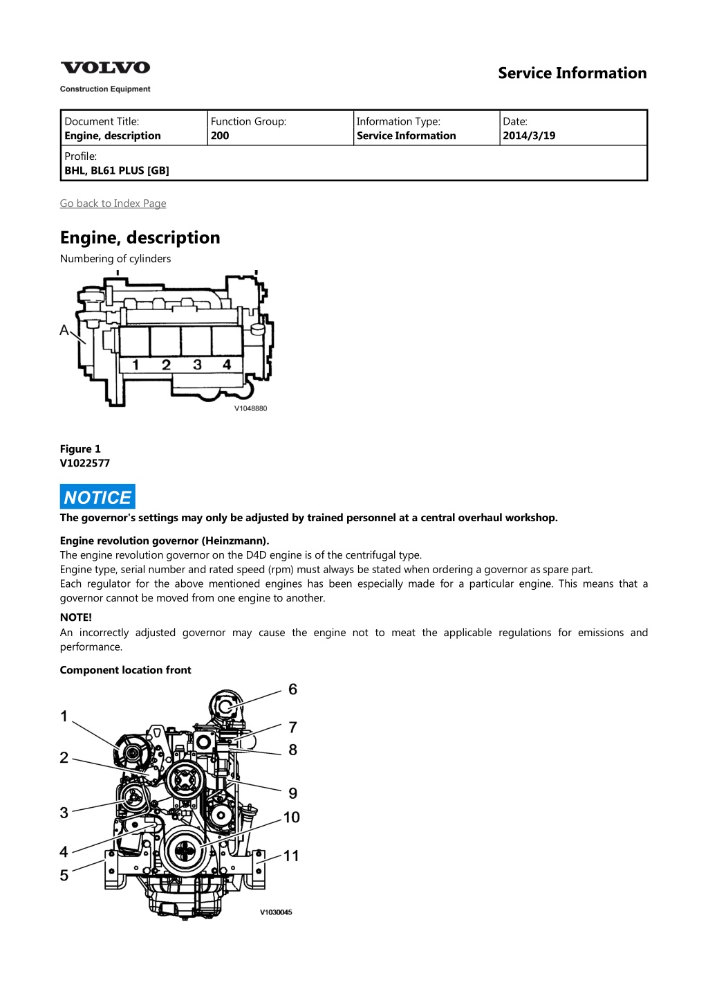
Service Information Document Title: Engine, description Function Group: 200 Information Type: Service Information Date: 2014/3/19 Profile: BHL, BL61 PLUS [GB] Go back to Index Page Engine, description Numbering of cylinders Figure 1 V1022577 NOTICE The governor's settings may only be adjusted by trained personnel at a central overhaul workshop. Engine revolution governor (Heinzmann). The engine revolution governor on the D4D engine is of the centrifugal type. Engine type, serial number and rated speed (rpm) must always be stated when ordering a governor as spare part. Each regulator for the above mentioned engines has been especially made for a particular engine. This means that a governor cannot be moved from one engine to another. NOTE! An incorrectly adjusted governor may cause the engine not to meat the applicable regulations for emissions and performance. Component location front
Figure 2 1. 2. 3. 4. 5. 6. 7. 8. 9. Alternator Fuel pump Water pump V-belt and tension pulley Right engine mount bracket Turbo charger exhaust Pre heater Coolant out Coolant in Crankshaft pulley Left engine mount bracket 10. 11. Component location left hand side Figure 3 V1030046 1. 2. 3. 4. 5. 6. 7. 8. Engine lifting eyes Coolant out Thermostat Coolant in Oil filler and dipstick Inlet manifold Exhaust manifold Starter motor Component location right hand side
Figure 4 V1030047 1. 2. 3. 4. 5. 6. 7. 8. 9. Injection pumps + Injectors Shutoff solenoid Oil pressure switch Oil drain plug Alternator Cooling fan Oil cooler Fuel filter Engine oil filter Component location rear side
https://www.ebooklibonline.com Hello dear friend! Thank you very much for reading. Enter the link into your browser. The full manual is available for immediate download. https://www.ebooklibonline.com
Figure 5 V1030048 1. 2. 3. 4. 5. 6. 7. 8. Turbocharger Coolant temperature sensor Oil filler and dipstick Cold start solenoid Governor Accelerator Flywheel Sump Component location top view Figure 6 V1030049 1. 2. 3. 4. 5. 6. 7. 8. 1st Cylinder 3rd Cylinder 2nd Cylinder 4th Cylinder Exhaust Governor Rocker cover Air inlet
Service Information Document Title: Engine, description Function Group: 200 Information Type: Service Information Date: 2014/3/19 Profile: BHL, BL61 PLUS [GB] Go back to Index Page Engine, description The engine is a four-cylinder, four-stroke, in-line diesel engine with direct injection, exhaust turbocharger, liquid cooling and internal, unregulated exhaust gas recirculation (EGR). To comply with exhaust gas limit values, the turbocharger is equipped with unregulated, internal exhaust gas recirculation (IEGR), which returns the exhaust gas within the cylinder head to the combustion air. The oxygen content of this exhaust is low. A lower oxygen content reduces the temperature spike during combustion and thereby reduces nitrogen oxide (NO?). The camshaft has an extra cam - the trailing cam. This causes the inlet valve to briefly open during the exhaust stroke so that exhaust gas also enters the engine intake system. In the subsequent induction stroke, this exhaust is sucked back in. There is no regulation of exhaust gas quantity. Engine data plate The engine data plate specifies model, engine number and power data. The engine number is also stamped into the crankcase. Model and engine number must be specified when ordering spare parts. The direction of rotation is found on the flywheel, anticlockwise. Firing order: 1-3-4-2 (cylinder no. 1 on the flywheel side). IMPORTANT! Adjustments to the regulator may only be performed by trained staff in an authorized central repair workshop. Figure 1 Engine data plate A. B. C. D. E. F. Engine type Spare part number Engine number Capacity Rated speed Timing setting Components, servicing view
Figure 2 Components, servicing view 1. 2. 3. 4. 5. 6. 7. 8. 9. Oil filler pipe Coolant pump Fuel pump Vibration damper Oil filter Engine mounting Fuel filter Oil sump Oil dipstick Oil cooler Attachment for power take-off Cylinder head Coolant supply 10. 11. 12. 13. Components, exhaust view
Figure 3 Components, exhaust view 1. 2. 3. 4. 5. 6. 7. 8. 9. Starter motor Turbocharger Engine fan Exhaust manifold Inlet manifold Transport device Crankcase ventilation Speed (rpm) sensor. Flywheel
Service Information Document Title: Engine, removal Function Group: 210 Information Type: Service Information Date: 2014/3/19 Profile: BHL, BL61 PLUS [GB] Go back to Index Page Engine, removal Op nbr 21070-1 14360000 Vacuum pump Lifting chains, min. 1000 kg (2200 lb) WARNING To avoid severe burns, DO NOT attempt the next procedure when the engine is HOT. Wait for the engine, silencer and tailpipe to cool before proceeding. NOTE! In general, all strip clamps that secure hoses and electrical cables must be removed. All disconnected hoses and open connections must be plugged. 821 Engine hood, removal 1. Remove the engine hood, see . 2. Detach cable from the bracket. Figure 1 1. Cable 3. Remove the grille and the front plate.
Figure 2 1. 2. Grille Front plate 4. Remove the clamps from both sides of the cooler. Figure 3 1. Clamp 900 Vacuum pump, connection 5. Connect the vacuum pump, see . 6. Open the locking device and let down the hydraulic oil cooler. Disconnect the hoses (4 hoses) from the hydraulic oil cooler. Turn off the vacuum pump after the hoses have been plugged.
Figure 4 1. 2. Locking device Hoses 7. Connect a drain hose to the valve and place the drain hose down into a container. Open the valve and drain the coolant into the container. Figure 5 1. 2. Valve Drain hose 8. Disconnect the radiator hoses and the lower hose (hidden). Remove the screws radiator-radiator casting. Figure 6 1. 2. 3. 4. 5. Hose Hose Hose Hose Screws 9. Remove the screws from both sides and lift out the hydraulic oil cooler and the radiator.
Figure 7 1. Screw 10. Remove the fan guard and the radiator casting. Figure 8 1. 2. Fan guard Radiator casting 11. Remove the fan. Figure 9 1. Fan
12. Remove the attaching screws (4 attaching screws, 2 underneath). Remove the nuts and remove the silencer. Figure 10 1. 2. Attaching screws Nuts 13. Loosen the hose clamp. Remove the screws and remove the air cleaner. Remove the screws (3 pcs) and remove the bracket. Figure 11 1. 2. 3. 4. Screws Hose clamp Screws Air cleaner 14. Disconnect hose from the engine. Figure 12
1. Hose 15. Disconnect the hoses (2 hoses, one hidden) from the engine and release the fuel filter/pump from the hydraulic tank. Figure 13 1. Hoses 16. Detach the seat , move the seat back, and lift up the rubber mat from the floor against the seat. Figure 14 1. 2. Seat Rubber mat 17. Remove the plate.
Figure 15 1. Plate 18. Remove the shift lever. Figure 16 19. Disconnect the hoses from the gearbox. Figure 17 1. 2. Hose Hose 20. Disconnect the hoses from the gearbox.
Figure 18 1. 2. 3. Hose Hose Hose 21. Disconnect the hose from the gearbox. Figure 19 1. Hose 22. Disconnect ground cables from the gearbox. Figure 20
1. 2. Ground cable Ground cable 23. Turn off the electric power with the battery disconnect switch and disconnect the ground cable. Figure 21 1. 2. Battery disconnect switch Ground cable 24. Disconnect the electrical cables from the starter motor. Figure 22 1. Electrical cable 25. Disconnect the fuel hoses from the fuel filter. Remove the fuel filter from the hydraulic tank. 26. Unscrew the nuts and remove the throttle control cable from the engine.
Figure 23 1. Nut 27. Disconnect the front propeller shaft from the gearbox unit. Figure 24 1. Propeller shaft 28. Disconnect the rear propeller shaft from the gearbox unit. Figure 25 1. Propeller shaft 29. Disconnect the connector from the working pump.
Figure 26 1. Connector 30. Remove the screws (2 screws) gearbox unit - working pump. Figure 27 1. Screw 31. Arrange a strap around the working pump and tighten the string using a pinch-bar. Pull the working pump away from the gearbox. Figure 28
1. 2. Strap Iron-bar lever 32. Remove the attaching screws for the engine. Figure 29 1. 2. Attaching screw Attaching screw 33. Remove the attaching screw from both sides of the gearbox. Figure 30 1. Attaching screw 34. Connect a lifting chain between the lifting eyes and a lifting device. Carefully lift and balance the engine/gearbox unit when the unit is lifted out.
Suggest: If the above button click is invalid. Please download this document first, and then click the above link to download the complete manual. Thank you so much for reading
Figure 31 1. 2. Lifting eye Lifting eye 35. Place the engine on stable supports. Make sure that the gearbox unit is dismountable. See .Gearbox, removal in Section 4 Figure 32
https://www.ebooklibonline.com Hello dear friend! Thank you very much for reading. Enter the link into your browser. The full manual is available for immediate download. https://www.ebooklibonline.com