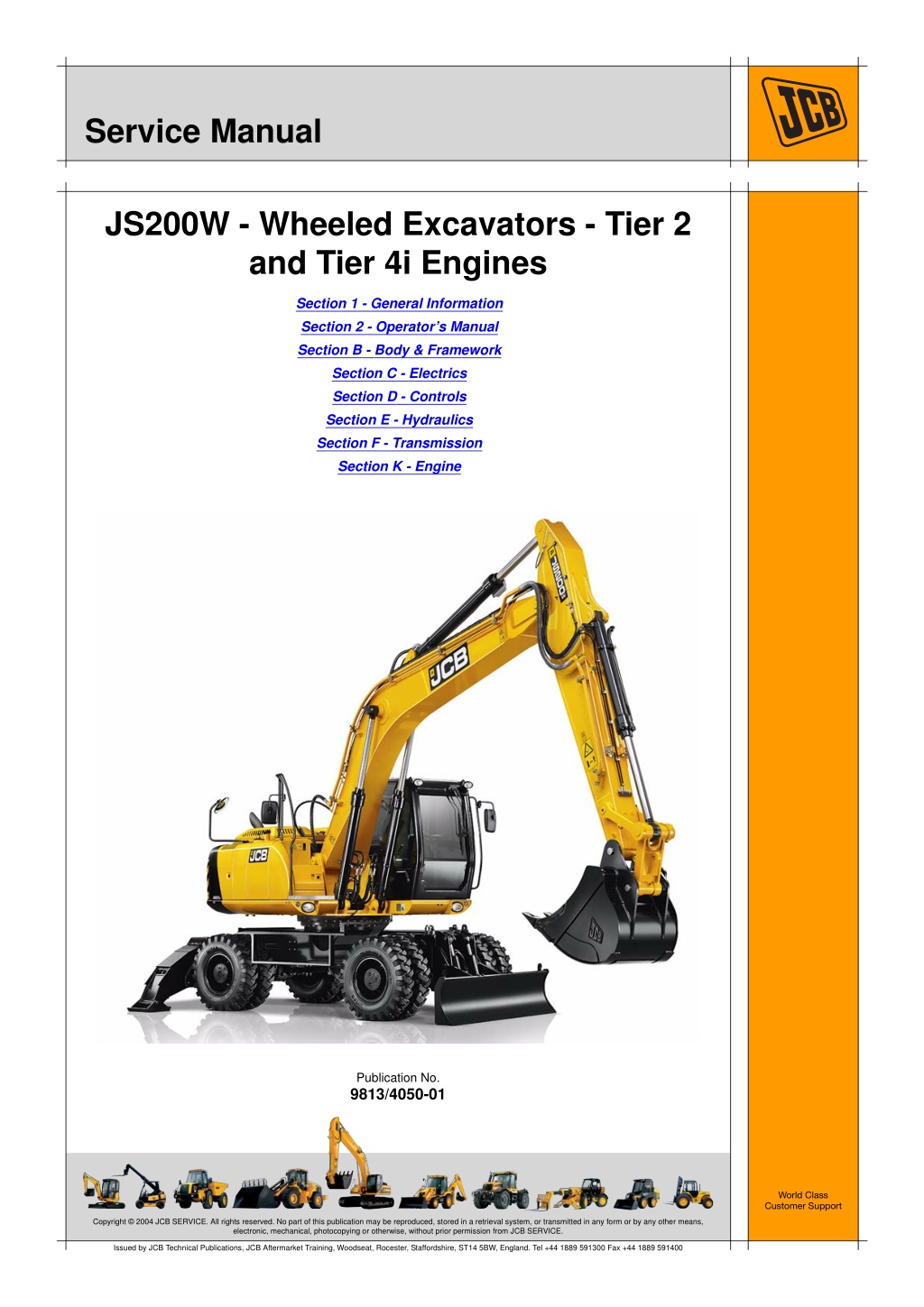
JCB JS200W Tier 2 and Tier 4i Wheeled Excavator Service Repair Manual Instant Download (From 2436101 To 2436300; From 2143861 To 2144192)
Please open the website below to get the complete manualnn//
Download Presentation

Please find below an Image/Link to download the presentation.
The content on the website is provided AS IS for your information and personal use only. It may not be sold, licensed, or shared on other websites without obtaining consent from the author. Download presentation by click this link. If you encounter any issues during the download, it is possible that the publisher has removed the file from their server.
E N D
Presentation Transcript
Service Manual JS200W - Wheeled Excavators - Tier 2 and Tier 4i Engines Section 1 - General Information Section 2 - Operator s Manual Section B - Body & Framework Section C - Electrics Section D - Controls Section E - Hydraulics Section F - Transmission Section K - Engine Publication No. 9813/4050-01 World Class Customer Support Copyright 2004 JCB SERVICE. All rights reserved. No part of this publication may be reproduced, stored in a retrieval system, or transmitted in any form or by any other means, electronic, mechanical, photocopying or otherwise, without prior permission from JCB SERVICE. Issued by JCB Technical Publications, JCB Aftermarket Training, Woodseat, Rocester, Staffordshire, ST14 5BW, England. Tel +44 1889 591300 Fax +44 1889 591400
Section 1 General Information Service Manual - JS200W - Wheeled Excavators - Tier 2 and Tier 4i Engines Section 1 - General Information Section 2 - Operator s Manual Section B - Body & Framework Section C - Electrics Section D - Controls Section E - Hydraulics Section F - Transmission Section K - Engine Publication No. 9813/4050-01 World Class Customer Support Copyright 2004 JCB SERVICE. All rights reserved. No part of this publication may be reproduced, stored in a retrieval system, or transmitted in any form or by any other means, electronic, mechanical, photocopying or otherwise, without prior permission from JCB SERVICE. Issued by JCB Technical Publications, JCB Aftermarket Training, Woodseat, Rocester, Staffordshire, ST14 5BW, England. Tel +44 1889 591300 Fax +44 1889 591400
Section 1 - General Information Contents Introduction Identifying Your Machine ........................................................................... 1-1 Page No. Safety Introduction ................................................................................................ 1-3 Use Introduction ................................................................................................ 1-5 Scope ........................................................................................................ 1-6 Personnel ..............................................................................................1-6 Applications ...........................................................................................1-6 Newest Data ..........................................................................................1-6 Format ....................................................................................................... 1-7 Left Side, Right Side .................................................................................. 1-8 Hydraulic Schematic Codes ...................................................................... 1-9 Colour Codes ........................................................................................1-9 Routine Maintenance Maintenance Schedules .......................................................................... 1-11 General Procedures Introduction .............................................................................................. 1-13 Parking the Machine and Making it Safe ................................................. 1-14 Venting the Hydraulic Pressure ............................................................... 1-15 Connecting/Disconnecting Hydraulic Hoses ............................................ 1-16 Battery Disconnection/Connection .......................................................... 1-17 Removing and Replacing Components ................................................... 1-18 Preparation ..........................................................................................1-18 Original Components ...........................................................................1-18 New Components ................................................................................1-18 Torques and Fixings ............................................................................1-18 Battery Charging System Precautions ..................................................... 1-19 Gas Hydraulic Bladder Accumulators ...................................................... 1-20 Replacement .......................................................................................1-20 Charging ..............................................................................................1-20 Service Consumables Introduction .............................................................................................. 1-23 Sealing and Retaining Compounds ......................................................... 1-24 Torque Settings Introduction .............................................................................................. 1-25 Zinc Plated Fasteners and Dacromet Fasteners ..................................... 1-26 Introduction ..........................................................................................1-26 Bolts and Screws .................................................................................1-26 Hydraulic Connections ............................................................................. 1-30 'O' Ring Face Seal System ..................................................................1-30 'Torque Stop' Hose System .................................................................1-36 `Positional Type' Hydraulic Adaptors ....................................................... 1-37 Fitting Procedure .................................................................................1-37 Service Tools Numerical List .......................................................................................... 1-39 1-i 1-i
https://www.ebooklibonline.com Hello dear friend! Thank you very much for reading. Enter the link into your browser. The full manual is available for immediate download. https://www.ebooklibonline.com
Section 1 - General Information Contents Contents Tool Detail Reference .............................................................................. 1-42 Section B - Body and Framework ........................................................1-42 Section C - Electrics ............................................................................1-46 Section E - Hydraulics .........................................................................1-47 Section H - Steering ............................................................................1-59 Page No. 1-ii 1-ii
Section 1 - General Information Introduction Identifying Your Machine For information about identifying your machine and its main components, refer to Section 2, About the Machine, Machine and Component Identification. 1-1 1-1 9813/4050-01
Section 1 - General Information Safety Introduction In this manual and on the machine there are safety notices. The safety notices have different signal words as follows: DANGER WARNING CAUTION Notice For an explanation of the safety notice signal words, refer to Section 2, Introduction, Safety. For general safety notices, refer to Section 2, Introduction, Safety. For maintenance safety notices, refer to Section 2, Maintenance, Maintenance Safety. For safety notices specific to maintenance procedures, refer to the relevant procedure. If you do not fully understand a safety notice ask your employer to explain it. 1-3 1-3 9813/4050-01
Section 1 - General Information Use Introduction This topic contains information about the structure of the manual and how to use the manual. K K Scope ( T T 1-6) K Personnel ( T K Applications ( T K Newest Data ( T T 1-7) T 1-6) T 1-6) T 1-6) K K K K K Format ( T K Left Side, Right Side ( T K Hydraulic Schematic Codes ( T K Colour Codes ( T T 1-8) K T 1-9) K T 1-9) K 1-5 1-5 9813/4050-01
Section 1 - General Information Use Scope Scope Personnel This manual is designed for the benefit of JCB Distributor Service Engineers who are receiving, or have received, training by JCB Technical Training Department. These personnel should have a sound knowledge of workshop practice, safety procedures, and general techniques associated with the maintenance and repair of hydraulic earthmoving equipment. remember above all else SAFETY MUST COME FIRST! Finally, please Applications This manual contains data relevant to a range of machines. Make sure you reference the data for the correct machine. Newest Data From time to time new machines, systems or devices require the manual to be re-issued. Make sure you have the newest issue. Always check the on-line JCB data system for relevant technical information. 1-6 1-6 9813/4050-01
Section 1 - General Information Use Format Format The manual is compiled in sections, the first two are numbered and contain information as follows: General Information - The section includes general information such as torque settings and service tools. 1 Operator Manual - The section contains a copy of the applicable machine Operator Manual. Refer to this section when necessary for information about the main machine components and controls. Refer also to the safety and daily / weekly maintenance information. 2 The remaining sections are alphabetically coded and deal with dismantling, overhaul etc. of specific components, for example: A B Attachments Body and Framework...etc. Each section contains data such as technical data, descriptions, fault finding and test procedures. Some sections contain procedures and specifications for different variants. This happens because of market requirements, or when the machine specification changes after a period of time. Where applicable, a table contains information to help you identify the correct data and procedures. 1-7 1-7 9813/4050-01
Section 1 - General Information Use Left Side, Right Side Left Side, Right Side In this manual, 'left' A and 'right' B mean your left and right when you are seated correctly in the machine. B A T017280-1 Fig 1. 1-8 1-8 9813/4050-01
Section 1 - General Information Use Hydraulic Schematic Codes Hydraulic Schematic Codes Colour Codes The following colour coding, used on illustrations to denote various conditions of oil pressure and flow, is standardised throughout JCB Service Publications. Full Pressure: Pressure generated from operation of a service. Depending on application this may be anything between neutral circuit pressure and LSRV operating pressure. Red Pressure: Pressure that is above neutral circuit pressure but lower than that denoted by Red. Pink Pilot: Oil pressure used in controlling a device (Pilot). Orange Neural: Neutral circuit pressure. Blue Green Exhaust: Cavitation: Oil subjected to a partial vacuum due to a drop in pressure (cavitation). Light Green Lock Up: Oil trapped within a chamber or line, preventing movement of components (lock up). Yellow 1-9 1-9 9813/4050-01
Section 1 - General Information Routine Maintenance Maintenance Schedules This publication contains procedures for carrying out the routine maintenance tasks listed on the maintenance schedules. Refer to Section 2, Maintenance Schedules. The procedures for the daily and weekly (10 and 50 hour) tasks are given in Section 2, Maintenance. The procedures for the 100 hour and above tasks are given in the related sections of this publication. For example the procedures for engine related tasks are given in Section K. 1-11 1-11 9813/4050-01
Section 1 - General Information General Procedures Introduction When work is done on the machine it is important that the correct care is taken. This will help to prevent personal injury and reduce the risk of component failure. As part of the procedures in this manual you will need to do some general procedures. Two examples of these general procedures are; parking the machine and making it safe, and venting hydraulic pressure. These procedures are given here as an alternative to again and again in the manual. Where applicable you will see a cross reference to this section so that you can refer to the detailed procedures. K K Parking the Machine and Making it Safe ( T K Venting the Hydraulic Pressure ( T K Connecting/Disconnecting Hydraulic Hoses ( T K Battery Disconnection/Connection ( T K Removing and Replacing Components ( T K Battery Charging System Precautions ( T K Gas Hydraulic Bladder Accumulators ( T T 1-14) T 1-15) K T 1-16) K T 1-17) K T 1-18) T 1-19) T 1-20) K K K 1-13 1-13 9813/4050-01
Section 1 - General Information General Procedures Parking the Machine and Making it Safe Parking the Machine and Making it Safe For the correct procedures to park and make the machine safe, refer to Section 2, Maintenance, Maintenance Positions. 1-14 1-14 9813/4050-01
Section 1 - General Information General Procedures Venting the Hydraulic Pressure Venting the Hydraulic Pressure !MWARNING Hydraulic Pressure Hydraulic fluid at system pressure can injure you. Before disconnecting or connecting hydraulic hoses or couplings, vent the pressure trapped in the hoses in accordance with the instructions given in this publication. HYD-1-5 For the correct procedures to vent the hydraulic pressure, refer to Section 2, Maintenance, Hydraulic System, General, Discharge. 1-15 1-15 9813/4050-01
Section 1 - General Information General Procedures Connecting/Disconnecting Hydraulic Hoses Connecting/Disconnecting Hydraulic Hoses !MWARNING Hydraulic Pressure Hydraulic fluid at system pressure can injure you. Before disconnecting or connecting hydraulic hoses or couplings, vent the pressure trapped in the hoses in accordance with the instructions given in this publication. HYD-1-5 For the correct procedures to connect/disconnect hydraulic hoses, refer to Section 2, Attachments, Connecting/Disconnecting Hydraulic Hoses. 1-16 1-16 9813/4050-01
Section 1 - General Information General Procedures Battery Disconnection/Connection Battery Disconnection/Connection For the correct procedures to disconnect/connect the battery, refer to Section 2, Maintenance, Electrical System, Battery. 1-17 1-17 9813/4050-01
Section 1 - General Information General Procedures Removing and Replacing Components Removing and Replacing Components Preparation Make sure that all the applicable component assemblies are correct. Make sure that the applicable fixings are to the correct specification. If necessary discard the original fixings and replace them with new ones. The relevant procedures indicate when this is necessary. Make sure that the applicable fixings and threaded holes are free from contamination. This includes; dirt, debris, old sealants and compounds, fluids and lubricants. Before removing and replacing components do the following: To prevent contamination of the machine systems, clean the machines in the area of the applicable components. Refer to Section 2, Preservation and Storage, Cleaning the Machine. Make sure that the correct maintenance procedures are available. Make sure that the correct tools and equipment are available. Make sure that the correct replacement parts, consumables, fluids and lubricants are available. This manual provides reference to the correct torque settings as follows: Where no torque setting is given in the applicable procedure, use the standard torque setting. To obtain the correct standard torque setting refer to Torque Settings in this section. Where torque settings are given in the applicable procedure use the settings given. These settings may be different to the standard torque settings in the case of special fixings for example. Original Components Always Install new oil seals, gaskets, etc. Components showing obvious signs of wear or damage should be replaced with new ones. Before re-installing original components do the following: Clean components using the applicable cleaning materials. Inspect components for signs of excessive wear or defects. Check the component specifications such as wear limits where applicable. New Components Make sure that the correct new components are installed. Do not substitute components from another machine. Components may look the same but may not be interchangeable. Refer to the JCB parts systems. Torques and Fixings When replacing components always tighten the applicable fixings to the correct torque. For the torque setting to be effective do the following before installing the fixings: 1-18 1-18 9813/4050-01
Section 1 - General Information General Procedures Battery Charging System Precautions Battery Charging System Precautions Obey the procedures below to prevent damage to the alternator and battery. Ensure that the battery negative terminal is connected to the earthing cable. Never make or break connections to the battery or alternator, or any part of the charging circuit whilst the engine is running. Disregarding this instruction will result in damage to the regulator or rectifying diodes. Main output cables are 'live' even when the engine is not running. Take care not to earth connectors in the moulded plug if it is removed from the alternator. When arc welding on the machine, protect the alternator by removing the moulded plug (or if separate output cables fitted, remove the cables). Follow the correct procedures when jump starting the engine. Refer to Section 2, Operation, Moving a Disabled Machine. 1-19 1-19 9813/4050-01
Section 1 - General Information General Procedures Gas Hydraulic Bladder Accumulators Gas Hydraulic Bladder Accumulators !MWARNING Some hydraulic circuits and valve blocks are fitted with gas hydraulic bladder type accumulators. Use only nitrogen gas to charge accumulators. The use of any other gas can cause the accumulators to explode. Remember that although nitrogen is not poisonous you can be killed by suffocation if it displaces the air in your workplace. Do not allow excessive quantities of nitrogen to be discharged into the atmosphere. Before removing accumulators make sure hydraulic pressure is vented. K K Venting Pressure ( T T 1-15) the Hydraulic Even when the hydraulic pressure is vented the accumulator still contains pressurised nitrogen gas. DO NOT attempt to discharge the gas pressure. B-3-1-6 DO NOT transport accumulators charged with pressurised gas by air freight. Replacement 2 1 Replacement accumulators are generally supplied in a discharged state with no nitrogen gas. A label attached to the accumulator indicates the gas charge state. 8 Charging 3 K K Fig 1. ( T T 1-20) 4 7 5 Important: The following charging procedure is only applicable to accumulators supplied in a discharged state. 6 To carry out the charging procedure the following is required: Pressurised bottle of nitrogen gas with a suitable pressure reducing valve (3). Correct gas bottle adaptor depending on territory. Charging kit 892/00239. Refer to Section 1. C110540-C2 Fig 1. Operating charge pressures; accumulators are charged to different operating pressures depending on the application. For the correct charge pressure refer to the applicable system specifications. Hold the accumulator upright and remove the plastic cap from the top of the accumulator. 1 Note: Some accumulators are supplied with a measured quantity of oil inside the gas chamber. Take care to prevent oil loss. Before fitting a replacement accumulator charge it with nitrogen gas as follows: Using a suitable allen key, slowly remove the filler plug 2. 2 Lightly oil the sealing washer beneath. Replace the washer and plug. Loosen the plug by 1/8 of a turn. 1-20 1-20 9813/4050-01
Section 1 - General Information General Procedures Gas Hydraulic Bladder Accumulators Connect the accumulator adaptor 1 (from kit 892/ 00239) to the accumulator. Connect the charging unit 6 to the accumulator adaptor. 3 Connect the charging hose to the pressure regulator 3 using the correct adaptor. Set the pressure regulator 3 to the minimum pressure. 1 Via the charging tool knob 7, open the filler plug 2 by three turns. 4 Open the discharge valve 5 on the charging unit. 5 3 2 Carefully open the nitrogen gas bottle valve 4 and confirm that the nitrogen gas flows freely. Shut the gas bottle valve and the discharge valve 5. Carefully open the gas bottle valve. Slowly increase the pressure using the gas bottle pressure regulator and watching the gauge 8 on the charging unit, allow nitrogen to flow until the pressure reading reaches 4 bar (72.5 psi) ABOVE the operating charge pressure. 6 C110550 Fig 2. K K Fig 2. ( T 3 and attach the pressurised warning label 2 at position 1 on the accumulator. T 1-21) Remove the discharged state label 12 Important: DO NOT exceed the maximum working pressure of the accumulator. The maximum working pressure is marked on the accumulator body. Install the accumulator and make sure the pressurised warning label is clearly visible. Close the gas bottle valve. Wait 10 minutes to dissipate the heat generated during charging. 7 Reduce the pressure in the accumulator to the specified operating charge pressure by carefully opening and closing the discharge valve 5. Turn the knob 7 to shut the filler plug 2 and tighten to a torque of 20 Nm (15 lb ft). 8 Release the pressure from the charging hose by opening the discharge valve 5. 9 Disconnect the charging unit and adaptor from the accumulator. Check the gas-tightness of filler plug 2 by pouring some oil around it. 10 Replace the plastic cap. 11 1-21 1-21 9813/4050-01
Section 1 - General Information Service Consumables Introduction Consumables such as sealing and retaining compounds are necessary to complete some procedures. Before you start work make sure that the consumables show in the tables are available. K K Sealing and Retaining Compounds ( T T 1-24) 1-23 1-23 1-07-01 Issue 01
Section 1 - General Information Service Consumables Sealing and Retaining Compounds Sealing and Retaining Compounds T11-001_4 Table 1. Type JCB Multi-Gasket Description A medium strength sealant suitable for all sizes of gasket flanges, and for hydraulic fittings of 25-65 mm diameter. A high strength locking fluid for use with threaded components. Gasketing for all sizes of flange where the strength of the joint is important. For all retaining parts which are unlikely to be dismantled. Part No. 4102/1212 Quantity 50 ml JCB High Strength Threadlocker 4102/0551 50 ml JCB Retainer (High Strength) 4101/0601 4101/0651 4101/0250 4101/0251 10 ml 50 ml 10 ml 50 ml JCB Threadlocker and Sealer A medium strength locking fluid for sealing and retaining nuts, bolts, and screws up to 50 mm diameter, and for hydraulic fittings up to 25 mm diameter. A high strength locking fluid for sealing and retaining nuts, bolts, and screws up to 50 mm diameter, and for hydraulic fittings up to 25 mm diameter. A medium strength thread sealing compound. A cleaning primer which speeds the curing rate of anaerobic products. JCB Threadlocker and Sealer (High Strength) 4101/0550 4101/0552 10 ml 200 ml JCB Threadseal JCB Activator 4102/1951 4104/0251 4104/0253 4104/1557 50 ml 200 ml (Aerosol) 1 ltr (Bottle) 400 ml (Aerosol) JCB Cleaner/Degreaser For degreasing components prior to use of anaerobic adhesives and sealants. For one pane of glass; comprises of: Direct Glazing Kit 993/55700 1 x Ultra Fast Adhesive (310 ml) 1 x Active Wipe 205 (30 ml) 1 x Black Primer 206J (30 ml) plus applicator nozzle etc. For direct glazing. For direct glazing. For direct glazing. To seal butt jointed glass. To seal plastic to metal joints. To finish exposed edges of laminated glass. Ultra Fast Adhesive Active Wipe 205 Black Primer 206J Clear Silicone Sealant Plastic to Metal Bonder Black Polyurethane Sealant 4103/2109 4104/1203 4201/4906 4102/0901 4103/0956 4102/2309 310 ml 250 ml 30 ml 50 g 310 ml 1-24 1-24 1-07-01 Issue 01
Suggest: If the above button click is invalid. Please download this document first, and then click the above link to download the complete manual. Thank you so much for reading
Section 1 - General Information Torque Settings Introduction This topic contains information about torques. Torque values are given for types and sizes of bolts and hydraulic connectors and adaptors. Where a torque is given as a single figure it may be varied by plus or minus 3%. Torque figures are given for fasteners with different surface treatments. Make sure you use the correct torque figures. Where torques are given in topics within the other sections always use these values. K K Zinc Plated Fasteners and Dacromet Fasteners ( T K Introduction ( T T 1-26) K Bolts and Screws ( T K Hydraulic Connections ( T K 'O' Ring Face Seal System ( T K 'Torque Stop' Hose System ( T K `Positional Type' Hydraulic Adaptors ( T K Fitting Procedure ( T T 1-26) K T 1-26) K T 1-30) K T 1-30) T 1-36) T 1-37) K K K T 1-37) K 1-25 1-25 1-05-01 Issue 02
https://www.ebooklibonline.com Hello dear friend! Thank you very much for reading. Enter the link into your browser. The full manual is available for immediate download. https://www.ebooklibonline.com

