Understanding Mobile Robot Kinematics for Navigation
Exploring the kinematics of wheeled locomotion in mobile robots, this content covers forward and inverse kinematics, instantaneous center of curvature, and the use of kinematics for robot navigation. Highlighting the challenges of measuring robot position and the integration of wheel velocities for motion estimation, it emphasizes the importance of expressing constraints in the global inertial frame for accurate positioning.

Download Presentation

Please find below an Image/Link to download the presentation.
The content on the website is provided AS IS for your information and personal use only. It may not be sold, licensed, or shared on other websites without obtaining consent from the author. Download presentation by click this link. If you encounter any issues during the download, it is possible that the publisher has removed the file from their server.
E N D
Presentation Transcript
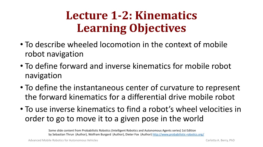
Lecture 1-2: Kinematics Learning Objectives To describe wheeled locomotion in the context of mobile robot navigation To define forward and inverse kinematics for mobile robot navigation To define the instantaneous center of curvature to represent the forward kinematics for a differential drive mobile robot To use inverse kinematics to find a robot s wheel velocities in order to go to move it to a given pose in the world Some slide content from Probabilistic Robotics (Intelligent Robotics and Autonomous Agents series) 1st Edition by Sebastian Thrun (Author), Wolfram Burgard (Author), Dieter Fox (Author) http://www.probabilistic-robotics.org/ Advanced Mobile Robotics for Autonomous Vehicles Carlotta A. Berry, PhD
Locomotion of Wheeled Robots Wheeled robots roll along the x-axis Examples of a differential drive robot would be the Pioneer 2-DX Also, some wheels may rotate about the z-axis Robots that are not holonomic cannot move along the y-axis Advanced Mobile Robotics for Autonomous Vehicles Carlotta A. Berry, PhD
Mobile Robot Kinematics Mobile Robot Kinematics is the dynamic model of how a mobile robot behaves Kinematics is a description of mechanical behavior of the robot for design and control Mobile Robot Kinematics is used for: Position estimation Motion estimation Some slide content from Probabilistic Robotics (Intelligent Robotics and Autonomous Agents series) 1st Edition by Sebastian Thrun (Author), Wolfram Burgard (Author), Dieter Fox (Author) http://www.probabilistic-robotics.org/ Advanced Mobile Robotics for Autonomous Vehicles Carlotta A. Berry, PhD
Mobile Robot Kinematics Mobile robots move unbounded with respect to their environment There is no direct way to measure robot position Position must be integrated over time from velocity (v = dp/dt) The integration leads to inaccuracies in position and motion estimation Each wheel contributes to the robot s motion and imposes constraints on the robot s motion All of the constraints must be expressed with respect to the reference frame (global inertial frame) Some slide content from Probabilistic Robotics (Intelligent Robotics and Autonomous Agents series) 1st Edition by Sebastian Thrun (Author), Wolfram Burgard (Author), Dieter Fox (Author) http://www.probabilistic-robotics.org/ Advanced Mobile Robotics for Autonomous Vehicles Carlotta A. Berry, PhD
Robot Reference Frame The robot s reference frame is three dimensional including position on the plane and the orientation, {XR, YR, } The axes {XG, YG},define the inertial global reference frame with origin, O The angular difference between the global and reference frames is Point P on the robot chassis in the global reference frame is specified by coordinates (x, y) The vectorGPR describes the location of the robot with respect to the inertial global reference frame. = T P x y G R Advanced Mobile Robotics for Autonomous Vehicles Carlotta A. Berry, PhD
Orthogonal Rotation Matrix The orthogonal rotation matrix is used to map motion in the global reference frame {XG, YG}to motion in the robot s local reference frame {XR, YR} The orthogonal rotation matrix is used to convert robot velocity in the global reference frame {XG, YG} to components of motion along the robot s local axes {XR, YR} The vectorPR describes the location of the robot with respect to the local reference frame. cos sin sin cos 0 0 0 1 ( ) = R 0 T ( ) ( ) = = G P R P R x y R R Advanced Mobile Robotics for Autonomous Vehicles Carlotta A. Berry, PhD
Rotation Example 1: Global to Local Reference Frame Suppose that a robot is at point P and = /2 and the robot s velocity with respect to the global reference frame is Find the robot s motion with respect to the local reference frame {XR, YR} The motion along XR and YR due to is ( , y , x ) 0 1 0 1 0 0 0 x y y = = = G 0 1 P R P x R R 2 Advanced Mobile Robotics for Autonomous Vehicles Carlotta A. Berry, PhD
Rotation Example 2: Local to Global Reference Frame Now suppose that a robot is at point P and = /2 and the robot s velocity with respect to its local frame is Find the robot s motion in the global reference frame {XG, YG} The motion along XG and YG due to is ( , y , x ) ( ) P P = 1 R G R R 0 1 0 0 1 x y y 1 = = = G 1 0 0 P R V x R R 2 0 Advanced Mobile Robotics for Autonomous Vehicles Carlotta A. Berry, PhD
Forward versus Inverse Kinematics Forward Kinematics involves estimating a mobile robot s motion and /or pose given the angular and linear velocity Inverse Kinematics involves determining the robot s angular and linear velocity to achieve a given robot motion and/or pose Some slide content from Probabilistic Robotics (Intelligent Robotics and Autonomous Agents series) 1st Edition by Sebastian Thrun (Author), Wolfram Burgard (Author), Dieter Fox (Author) http://www.probabilistic-robotics.org/ Advanced Mobile Robotics for Autonomous Vehicles Carlotta A. Berry, PhD
Forward Kinematics Model Forward Kinematicsprovides an estimate of the robot s position given its geometry and speed of its wheels It requires accurate measurement of the wheel velocities over time However, position error (accumulation error) grows with time Some slide content from Probabilistic Robotics (Intelligent Robotics and Autonomous Agents series) 1st Edition by Sebastian Thrun (Author), Wolfram Burgard (Author), Dieter Fox (Author) http://www.probabilistic-robotics.org/ Advanced Mobile Robotics for Autonomous Vehicles Carlotta A. Berry, PhD
Path and Trajectory Considerations There is a difference between DOF granted by steering versus direction control of wheel velocity The difference is in the context of trajectories rather than paths A trajectory is like a path but it has the additional dimension of time Motion control (kinematic control) is not straight forward because mobile robots are non-holonomic systems. Some slide content from Probabilistic Robotics (Intelligent Robotics and Autonomous Agents series) 1st Edition by Sebastian Thrun (Author), Wolfram Burgard (Author), Dieter Fox (Author) http://www.probabilistic-robotics.org/ Advanced Mobile Robotics for Autonomous Vehicles Carlotta A. Berry, PhD
Path and Trajectory Considerations A robot has a goal trajectory where it moves along the XI axis at a constant speed of 1 m/s for 1 second. Then the wheels adjust for 1 second. The robot then spins counterclockwise at 90 degrees in 1 second. Then the wheels adjust for 1 second. Finally, the robot moves parallel to axis YI for 1 final second. Advanced Mobile Robotics for Autonomous Vehicles Carlotta A. Berry, PhD
Forward Kinematics Model: Differential Drive Robot Consider a differential drive robot which has 2 wheels with radius r, a point P centered between the 2 drive wheels and each wheel is a distancel from P If the rotational speed of the 2 wheels is and then the forward kinematic model is x P = = y , r , l ( f , , ) G 2 1 R 1 2 Some slide content from Probabilistic Robotics (Intelligent Robotics and Autonomous Agents series) 1st Edition by Sebastian Thrun (Author), Wolfram Burgard (Author), Dieter Fox (Author) http://www.probabilistic-robotics.org/ Advanced Mobile Robotics for Autonomous Vehicles Carlotta A. Berry, PhD
Linear Velocity for Differential Drive Robot y For a differential drive linear velocity is given by the following equations where (x, y, ) is the pose, R is the radius of the ICC, l is the width of the robot, vl and vr are the linear velocity. ICC vl R r x (x,y) For linear velocity in the x direction, each wheel contributes one half of the total speed v vr l/2 Since wheels cannot move sideways, the velocity in the y direction is zero ( ) ( ) t ( v ) ( ) ( ) = = = = 1 2 1 2 x r v = 1 2 1 2 x r v 1 1 r l 2 2 r r x + x r 1 r 2 Advanced Mobile Robotics for Autonomous Vehicles Carlotta A. Berry, PhD
Angular Velocity for Differential Drive Robot The angular velocity about is calculated from the contribution from each of the two wheels working alone. The right wheel contributes counterclockwise rotation 1 around the left wheel. The left wheel contributes clockwise rotation 2 about the right wheel. Each rotation has a radius of 2l. r = 1 1 l 2 r = 2 2 l 2 + = = ( ( / 2) / 2) + R R l l v v r l ( ) ) l v v v l r = R 2 ( v v r v l r l = Advanced Mobile Robotics for Autonomous Vehicles Carlotta A. Berry, PhD l
Forward Kinematics for Differential Drive Robot ' ' ' cos( sin( ) ) sin( cos( ) 0 0 1 ICC ICC ICC ICC x y t t t x y x x = + ) t y y 0 0 t t = ( ) cos[ ( )] ( ) x t v d 0 t = ( ) sin[ ( )] ( ) y t v d 0 t = ( ) t ( ) d 0 Advanced Mobile Robotics for Autonomous Vehicles Carlotta A. Berry, PhD
Forward Kinematics for Differential Drive Robot ' ' ' cos( sin( ) ) sin( cos( ) 0 0 1 ICC ICC ICC ICC x y t t t x y x x = + ) t y y 0 0 t t 1 2 = + ( )] cos[ ( )] ( ) x t [ ( ) r v v d l 0 t 1 2 = + ( )] sin[ ( )] ( ) y t [ ( ) r v v d l 0 t 1 l = ( )] ( ) t [ ( ) r v v d l 0 Advanced Mobile Robotics for Autonomous Vehicles Carlotta A. Berry, PhD
Complete Forward Kinematics Model for Differential Drive Robot Given the robot s rotation with respect to the global reference frame, wheel velocities, radius of the wheels and distance between the wheels it is possible to find the robot s velocity with respect to the global reference frame. The complete forward kinematic model is x r ( ) ( ) P P = = 1 1 R R y G R R r r r r + + cos sin sin cos 0 0 0 1 x x l r r l 2 2 ( ) 1 = = G 0 0 P R R 0 r r l r l r l 2 2 l Advanced Mobile Robotics for Autonomous Vehicles Carlotta A. Berry, PhD
Lecture 1-2: Kinematics Learning Objectives To define forward and inverse kinematics for mobile robot navigation To define the instantaneous center of curvature to represent the forward kinematics for a differential drive mobile robot To use inverse kinematics to find a robot s wheel velocities in order to go to move it to a given pose in the world Some slide content from Probabilistic Robotics (Intelligent Robotics and Autonomous Agents series) 1st Edition by Sebastian Thrun (Author), Wolfram Burgard (Author), Dieter Fox (Author) http://www.probabilistic-robotics.org/ Advanced Mobile Robotics for Autonomous Vehicles Carlotta A. Berry, PhD
Instantaneous Center of Curvature (Rotation) In order for the robot to roll, each wheel must roll along the x-axis where their y axes intersect at the instantaneous center of curvature [ICC] (rotation) [ICR] ICC Advanced Mobile Robotics for Autonomous Vehicles Carlotta A. Berry, PhD
Instantaneous Center of Rotation The ICR has a zero-motion line drawn through the horizontal axis perpendicular to the wheel plane The wheel moves along a radius R with center on the zero-motion line, the center of the circle is the ICR ICR is the point around which each wheel of the robot makes a circular course The ICR changes over time as a function of the individual wheel velocities Larger difference in wheel velocities make small radius Smaller difference in wheel velocities makes larger radius ICR ICR ICR Advanced Mobile Robotics for Autonomous Vehicles Carlotta A. Berry, PhD
Instantaneous Center of Rotation When R is infinity, wheel velocities are equivalent, and the robot moves in a straight line When R is zero, wheel velocities are the negatives of each other and the robot spins in place All other cases, R is finite and non-zero and the robot follows a curved trajectory about a point which is a distance R from the robot s center Note that differential drive robots are very sensitive to the velocity differences between the two wheels making it hard to move in a perfectly straight line Advanced Mobile Robotics for Autonomous Vehicles Carlotta A. Berry, PhD
ICC for Differential Drive Robot y For a differential drive robot, the ICC is given by the following equation where R is the radius of the ICC, and (x, y, ) is the pose of the robot ICC vl R x (x,y) vr = + l/2 ICC [ sin , cos ] x R y R Advanced Mobile Robotics for Autonomous Vehicles Carlotta A. Berry, PhD
Forward Kinematics with the ICR Assume that at each instance of time, the robot is following the ICR with radius R at angular rate ( ) 1 v v V = robot forward velocity = 2 l 2 v1 right wheel velocity v2 left wheel velocity - robot angular velocity ( ( ) + V l v v = = R 1 2 ) v v 1 2 l distance from robot center to wheel Advanced Mobile Robotics for Autonomous Vehicles Carlotta A. Berry, PhD
Forward Kinematics with the ICR Given some control parameters (e.g. wheel velocities) determine the pose of the robot The position can be determined recursively as a function of the velocity and position, pR(t + ) = F(v1, v2) pR(t) To solve for the ICR center at an instance of time use the following ICR(t) = (ICRx, ICRy) = (x t R sin t, y t + R cos t) Advanced Mobile Robotics for Autonomous Vehicles Carlotta A. Berry, PhD
Forward Kinematics: Instantaneous Pose At time t + , the robot s pose with respect to the ICR is ( ) + = + 1 p t ( R ) R p ) t ( R ICR ) t ( G ( ( ( ) ) ) ( ( 0 ) ) ( 0 ) + cos x t cos sin 0 x ) t ( ICR G R R x ( ) + = + = + p t ( ) y t sin 0 y ) t ( ICR G G R R R y + t 1 ) t ( G R R Advanced Mobile Robotics for Autonomous Vehicles Carlotta A. Berry, PhD
Forward Kinematics: Linear Displacement When v1 = v2 = vt, R = , the robot moves in a straight line so ignore the ICR and use the following equations: x(t + ) = xt + vt cos t y(t + ) = yt + vt sin t (t + ) = t Advanced Mobile Robotics for Autonomous Vehicles Carlotta A. Berry, PhD
Forward Kinematics Example 1 Linear Displacement A differential steering robot with l = 5.3 cm starts at (xo, yo) = (20 cm, 20 cm), = 0 , t = 0 seconds The robot moves both wheels at 2 cm/sec and moves for 10 seconds Where is the robot at t = 10 seconds? x(t + ) = xt + vt cos t x(10) = x(0) + v(0) (10) cos(0 ) = 40 cm y(t + ) = yt + vt sin t y(10) = y(0) + v(0) (10) sin(0 ) = 20 cm (t + ) = t (10) = (0) = 0 y Robot at (20 cm, 10 cm, 0 ) at 0 seconds Robot at (40 cm, 20 cm, 0 ) at 10 seconds x Advanced Mobile Robotics for Autonomous Vehicles Carlotta A. Berry, PhD
Forward Kinematics Example 2 Counterclockwise turn A differential steering robot with l = 5.3 cm now sets the right wheel to 3 cm/s and the left wheel to 2 cm/s and moves for 10 more seconds R = l(v1 + v2)/(v1 - v2) = (5.3)(3+2)/(3-2) = 26.5 cm = (v1 - v2)/2l = 0.094 rad/s x(t + ) = Rcos( ) sin( t) + Rsin ( ) cos ( t) + xt - R sin( t) x(20) = (26.5)(0.587)(0)+26.5(0.810) (1) + 40-26.5(0) = 61.465 cm y(t + ) = Rsin( ) sin( t) - Rcos( ) cos ( t) + yt + Rcos( t) y(20) = (26.5)(0.810)(0) - 26.5(1)(0.587)+ 20 + 26.5(1) = 30.95 cm Where is the robot at t = 20 seconds, = 10 seconds? (t + ) = t + (20) = (10) + (10) = 0 + (0.09433 rad/s)(10 sec) = 54 Advanced Mobile Robotics for Autonomous Vehicles Carlotta A. Berry, PhD
Forward Kinematics Example 2 Counterclockwise turn y ICR R Robot at (20 cm, 10 cm, 0 ) at 0 seconds Robot at (40 cm, 20 cm, 0 ) at 10 seconds Robot at (61 cm, 31 cm, 54 ) at 20 seconds x Advanced Mobile Robotics for Autonomous Vehicles Carlotta A. Berry, PhD
Forward Kinematics Example 3 Counterclockwise spin Now set the robots right wheel to 2 cm/s and the left wheel to -2 cm/s for 5 seconds Where is the robot at t = 25 s, = 5 seconds? = (v1 - v2)/2l = (2 (- 2)cm/s)/10.6 cm = 0.37736 rad/s x(25) = 61.465 cm, y(25) = 30.95 cm, (25) = (20) + = 54 + (0.377rad/s)(5s) = 162 y Robot at (61 cm, 31 cm, 162 ) at 25 seconds Robot at (20 cm, 10 cm, 0 ) at 0 seconds Robot at (40 cm, 20 cm, 0 ) at 10 seconds Robot at (61 cm, 31 cm, 54 ) at 20 seconds x Advanced Mobile Robotics for Autonomous Vehicles Carlotta A. Berry, PhD
Forward Kinematics Example 3 Counterclockwise spin Now set the robots right wheel to 2 cm/s and the left wheel to -2 cm/s for 5 seconds Where is the robot at t = 25 s, = 5 seconds? = (v1 - v2)/2l = (2 (- 2)cm/s)/10.6 cm = 0.37736 rad/s x(25) = 61.465 cm, y(25) = 30.95 cm, (25) = (20) + = 54 + (0.377rad/s)(5s) = 162 Advanced Mobile Robotics for Autonomous Vehicles Carlotta A. Berry, PhD
Forward Kinematics Example 3 Counterclockwise spin y Robot at (61 cm, 31 cm, 162 ) at 25 seconds Robot at (20 cm, 10 cm, 0 ) at 0 seconds Robot at (40 cm, 20 cm, 0 ) at 10 seconds Robot at (61 cm, 31 cm, 54 ) at 20 seconds x Advanced Mobile Robotics for Autonomous Vehicles Carlotta A. Berry, PhD
Forward Kinematics Example 3 Counterclockwise spin Now set the robots right wheel to 2 cm/s and the left wheel to -2 cm/s for 5 seconds Where is the robot at t = 25 s, = 5 seconds? = (v1 - v2)/2l = (2 (- 2)cm/s)/10.6 cm = 0.37736 rad/s x(25) = 61.465 cm, y(25) = 30.95 cm, (25) = (20) + = 54 + (0.377rad/s)(5s) = 162 y Robot at (61 cm, 31 cm, 162 ) at 25 seconds Robot at (20 cm, 10 cm, 0 ) at 0 seconds Robot at (40 cm, 20 cm, 0 ) at 10 seconds Robot at (61 cm, 31 cm, 54 ) at 20 seconds x Advanced Mobile Robotics for Autonomous Vehicles Carlotta A. Berry, PhD
Forward Kinematics: Clockwise Turn Now set the robot s right wheel to 3 cm/s and the left wheel to 3.5 cm/sec for 15 seconds Where is the robot at t = 40 seconds, = 15 seconds? x(40) = 23.52 cm y(40) = 60.55 cm (40) = (25) + = 162 - (0.047 rad/s)(15 sec) = 121 Advanced Mobile Robotics for Autonomous Vehicles Carlotta A. Berry, PhD
Forward Kinematics: Clockwise Turn Robot at (24 cm, 61 cm, 121 ) at 40 seconds Robot at (61 cm, 31 cm, 162 ) at 25 seconds Robot at (20 cm, 10 cm, 0 ) at 0 seconds Robot at (40 cm, 20 cm, 0 ) at 10 seconds Robot at (61 cm, 31 cm, 54 ) at 20 seconds Advanced Mobile Robotics for Autonomous Vehicles Carlotta A. Berry, PhD
Forward Kinematics: Clockwise Pivot Finally, the robot sets the right wheel to 0 cm/s and the left wheel to 3 cm/s for 10 s. Where is the robot at t = 50 s, = 10 s? R = (5.3)( 3 + 0)/(0 - 3) = -5.3 cm = (0 3)/10.6 = -0.28202 rad/s x(50) = 31.5 cm y(50) = 67.47 cm (50) = (40) + = 121 - (0.283 rad/s)(10 sec) = -41 Advanced Mobile Robotics for Autonomous Vehicles Carlotta A. Berry, PhD
Robot at (32 cm, 67 cm, -41) at 50 seconds Forward Kinematics: Clockwise Pivot Robot at (24 cm, 61 cm, 121 ) at 40 seconds Robot at (61 cm, 31 cm, 162 ) at 25 seconds Robot at (20 cm, 10 cm, 0 ) at 0 seconds Robot at (40 cm, 20 cm, 0 ) at 10 seconds Robot at (61 cm, 31 cm, 54 ) at 20 seconds
Lecture 1-2: Kinematics Learning Objectives To define forward and inverse kinematics for mobile robot navigation To define the instantaneous center of curvature to represent the forward kinematics for a differential drive mobile robot To use inverse kinematics to find a robot s wheel velocities in order to go to move it to a given pose in the world Some slide content from Probabilistic Robotics (Intelligent Robotics and Autonomous Agents series) 1st Edition by Sebastian Thrun (Author), Wolfram Burgard (Author), Dieter Fox (Author) http://www.probabilistic-robotics.org/ Advanced Mobile Robotics for Autonomous Vehicles Carlotta A. Berry, PhD
Kinematic Controller The objective of a kinematic controlleris to have the robot follow a trajectory described by its position and/or velocity profiles as function of time. A trajectory is like a path, but it has the additional dimension of time Motion control (kinematic control) is not straight forward because mobile robots are non- holonomic systems (and may require the derivative of a position variable). Advanced Mobile Robotics for Autonomous Vehicles Carlotta A. Berry, PhD
Kinematic Controller yI goal One method is to divide the trajectory (path) into motion segments of clearly defined shape: straight lines and segments of a circle. (open loop control) control problem: pre-compute a smooth trajectory based on line and circle segments xI Advanced Mobile Robotics for Autonomous Vehicles Carlotta A. Berry, PhD
Kinematic Model Assume that the goal of the robot is the origin of the global inertial frame. The kinematics for the differential drive mobile robot with respect to the global reference frame are: x cos 0 v = = PR y sin 0 G 0 1 Advanced Mobile Robotics for Autonomous Vehicles Carlotta A. Berry, PhD
Feedback Control Example Given a robot with an arbitrary position and orientation and a predefined goal position and orientation. Design a control matrix for a real-state feedback controller to drive the pose error to zero. yR x ) t ( v R xR error + _ v(t) y K ) t ( R (t) R start e Transducer (encoder) goal Advanced Mobile Robotics for Autonomous Vehicles Carlotta A. Berry, PhD
Kinematic Model (cartesian) Assume that the goal of the robot is the origin of the global inertial frame. The kinematics for the differential drive mobile robot with respect to the global reference frame are: I x cos 0 v = y sin 0 0 1 y Advanced Mobile Robotics for Autonomous Vehicles Carlotta A. Berry, PhD
Kinematic Model (polar) Robot is facing the goal point Robot s back is to the goal point 2 ( 2 ( ( , 2 , 2 , Advanced Mobile Robotics for Autonomous Vehicles Carlotta A. Berry, PhD
The Control Law The controls signals v and must be designed to drive the robot from ( o, o, o) to the goal position Consider the control law, v = k and = k +k The closed loop system description becomes,
Kinematic Position Control Advanced Mobile Robotics for Autonomous Vehicles Carlotta A. Berry, PhD
Inverse Kinematics Inverse Kinematics is determining the control parameters (wheel velocities) that will make the robot move to a new pose from its current pose This is a very difficult problem Too many unknowns, not enough equations and multiple solutions The easy solution is to Spin the robot to the desired angle Move forward to the desired location Advanced Mobile Robotics for Autonomous Vehicles Carlotta A. Berry, PhD
Inverse Kinematics Approximate a desired path with arcs based upon computing ICR values Result is a set of straight-line paths and ICR arc potions Either set the robot drive time and compute velocities for each portion of the path Or set velocities and compute drive time for each portion of the path Advanced Mobile Robotics for Autonomous Vehicles Carlotta A. Berry, PhD
Inverse Kinematics: Spin Time and Velocities The spin time is determined from the wheel velocities ( t + ) = (t) + = [ ( t + ) - ( t)]/ Since = (v1 v2)/(2l) and v1 = -v2 = v1 /l = l [ ( t + ) - ( t)]/v1 Alternately, set the spin time and calculate the wheel velocities v1 = l ( ( t + ) - ( t) )/ Advanced Mobile Robotics for Autonomous Vehicles Carlotta A. Berry, PhD


")


")
")