Caterpillar Cat 307 TRACK-TYPE EXCAVATOR (Prefix 2PM) Service Repair Manual Instant Download 8
Please open the website below to get the complete manualnn//

Download Presentation

Please find below an Image/Link to download the presentation.
The content on the website is provided AS IS for your information and personal use only. It may not be sold, licensed, or shared on other websites without obtaining consent from the author. Download presentation by click this link. If you encounter any issues during the download, it is possible that the publisher has removed the file from their server.
E N D
Presentation Transcript
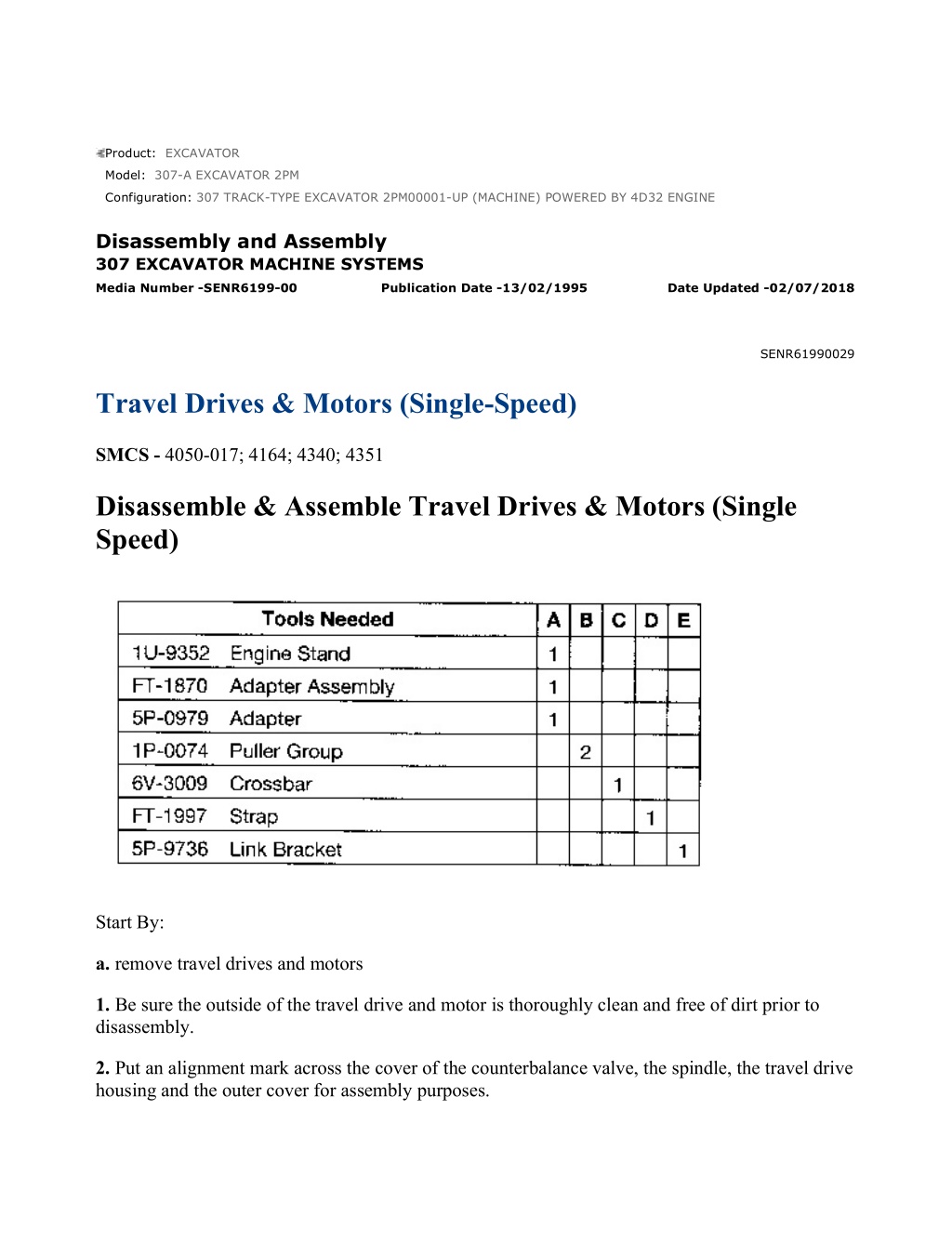
w 1/23(W) Product: EXCAVATOR Model: 307-A EXCAVATOR 2PM Configuration: 307 TRACK-TYPE EXCAVATOR 2PM00001-UP (MACHINE) POWERED BY 4D32 ENGINE Disassembly and Assembly 307 EXCAVATOR MACHINE SYSTEMS Media Number -SENR6199-00 Publication Date -13/02/1995 Date Updated -02/07/2018 SENR61990029 Travel Drives & Motors (Single-Speed) SMCS - 4050-017; 4164; 4340; 4351 Disassemble & Assemble Travel Drives & Motors (Single Speed) Start By: a. remove travel drives and motors 1. Be sure the outside of the travel drive and motor is thoroughly clean and free of dirt prior to disassembly. 2. Put an alignment mark across the cover of the counterbalance valve, the spindle, the travel drive housing and the outer cover for assembly purposes. https://127.0.0.1/sisweb/sisweb/techdoc/techdoc_print_page.jsp?returnurl=/sisweb/sis... 2021/12/26
w 2/23(W) 3. Remove 12 bolts (1) that hold sprocket (2) to the travel drive assembly. Using two persons, remove the sprocket from the travel drive. The weight of the sprocket is approximately 23 kg (50 lb). 4. Fasten the travel drive and motor to Tooling (A) with the outer cover facing up. The weight of the travel drive and motor, without the sprocket, is 55 kg (210 lb). Drain the oil from the travel drive and motor into a suitable container for storage or disposal. The capacity of the travel drive and motor is 2.4 liters (.6 U.S. gal). 5. Using a screwdriver or a .010 to .015 in feeler gauge, remove ring (3) from the groove between the cover and the travel drive housing. 6. Temporarily remove the fill and drain plugs from the outer cover. Install Tooling (B) in the fill and drain plug holes. Remove outer cover (4) from the travel drive housing with Tooling (B). https://127.0.0.1/sisweb/sisweb/techdoc/techdoc_print_page.jsp?returnurl=/sisweb/sis... 2021/12/26
w 3/23(W) 7. Remove O-ring seal (5) from outer cover (4). 8. Remove three retaining rings (6) and three gears (7). Remove the retaining ring and gear (8). Remove spacer (9) from each shaft. 9. Remove and disassemble the counterbalance valve as follows: a. Using Tooling (A), turn the travel drive and motor over. b. Remove six socket head bolts (10) and counterbalance valve (11) from the travel drive and motor. https://127.0.0.1/sisweb/sisweb/techdoc/techdoc_print_page.jsp?returnurl=/sisweb/sis... 2021/12/26
https://www.ebooklibonline.com Hello dear friend! Thank you very much for reading. Enter the link into your browser. The full manual is available for immediate download. https://www.ebooklibonline.com
w 4/23(W) c. Remove eight springs (12) from the cover. d. Put an alignment mark on timing plate (13) and the cover for assembly purposes. Remove timing plate (13) from the cover. e. Remove bearing (14) from the cover. f. If necessary, remove two dowels (15) from the cover. g. Remove valve (16) from the cover. h. Using a small diameter steel rod, push down on seat (18). While holding pressure on the seat, remove retaining ring (17). Remove seat (18), spring (19) and valve (20) from the cover. Remove O-ring seal (21) from the seat. https://127.0.0.1/sisweb/sisweb/techdoc/techdoc_print_page.jsp?returnurl=/sisweb/sis... 2021/12/26
w 5/23(W) i. Remove two plugs (22), two springs (23) and two spring retainers (26) from the cover. Remove spool (24) from the cover. Remove O-ring seal (25) from each plug (22). j. Remove two plugs (27), two springs (28) and two valves (29) from the cover. Remove O-ring seal (30) from each plug (27). 10. Remove O-ring seals (31) and (33) from the spindle. If necessary, remove two dowels (32) from the spindle. https://127.0.0.1/sisweb/sisweb/techdoc/techdoc_print_page.jsp?returnurl=/sisweb/sis... 2021/12/26
w 6/23(W) Piston (34) must be removed from the spindle with shop air. The piston can come out of the spindle with force during the removal procedure. To prevent possible personal injury, install Tool (C) as shown. Tool (C) will retain the piston in the spindle when applying shop air pressure. 11. Install Tool (C) on the spindle as shown. Use suitable sized bolts and large flat washers to hold Tool (C) in place. Apply shop air pressure (free of water) of approximately 525 kPa (75 psi) to release port (X). The piston will move up and out of the bore in the spindle. Remove Tool (C) and piston (34) from the spindle. 12. Remove back-up rings (35) and (37) and O-ring seals (36) and (38) from piston (34). 13. Remove friction plates and separator plates (39) from the spindle. NOTICE During removal of barrel assembly (40) from the spindle, do not let the components fall apart. The piston assemblies in the barrel assembly should be reinstalled in their original bores in the retainer plate and the barrel. 14. Using Tooling (A), turn the travel drive assembly on its side, and remove barrel assembly (40). https://127.0.0.1/sisweb/sisweb/techdoc/techdoc_print_page.jsp?returnurl=/sisweb/sis... 2021/12/26
w 7/23(W) 15. Disassemble barrel assembly (40) as follows: a. Put identification marks on nine piston assemblies (41) as to their location in retainer plate (42) and barrel (40). Remove the piston assemblies from the retainer plate and barrel. b. Remove guide (43) and spacer (44) from barrel (40). Remove the three pins from the barrel. There is spring force against washer (46). When retaining ring (45) is removed, the spring force will be released. To prevent possible personal injury, removal of the internal components in barrel (40) should be performed in a press in order to retain spring (47) and washer (46). https://127.0.0.1/sisweb/sisweb/techdoc/techdoc_print_page.jsp?returnurl=/sisweb/sis... 2021/12/26
w 8/23(W) c. Put barrel (40) in a press. Install a suitable size drive plate [one which will provide clearance for removal of retaining ring (45)] on washer (46). Put slight compression on washer (46) with the press. Remove retaining ring (45), and slowly release the spring compression. NOTE: Washers (46) and (48) are the same. d. Remove washer (46), spring (47) and washer (48) from barrel (40). 16. Remove swashplate (49) and shaft (50) as a unit. Using a soft faced hammer, tap the end of the shaft from the reduction gear side of the travel drive. Remove swashplate (49) from shaft (50). 17. Remove bearing (51) from shaft (50) with a press. 18. Remove oil seal (53) from the spindle. 19. If necessary, remove pin (52) from the spindle. https://127.0.0.1/sisweb/sisweb/techdoc/techdoc_print_page.jsp?returnurl=/sisweb/sis... 2021/12/26
w 9/23(W) NOTE: Tool (D) is used to hold the spindle and travel drive housing together as a unit. 20. Using suitable sized bolts, washers and nuts, install Tool (D) over the spindle as shown. 21. Turn the spindle and housing over. 22. Put an identification marks on retaining rings (54) and flange plate (56) as to their location. The flange plate and retaining rings must be reinstalled in its original position in the housing and on the three shafts. 23. Remove three retaining rings (54). NOTICE The thread lock compound used on reamer bolts (55) may cause the bolts to seize during removal. The reamer bolts should be removed slowly by hand. Do not use an impact wrench. If the reamer bolts will no longer turn during the removal procedure, do not use force to complete the removal. Instead, re-tighten the reamer bolts; then try loosening them again. 24. Slowly remove three reamer bolts (55) by hand. 25. Remove flange plate (56) from the spindle. https://127.0.0.1/sisweb/sisweb/techdoc/techdoc_print_page.jsp?returnurl=/sisweb/sis... 2021/12/26
w 10/23(W) 26. Remove three retaining rings (58) and three races (57) from the flange plate. 27. Remove inner race (59) from the flange plate with a hammer and punch. 28. Remove balls (60) from the outer race. 29. Remove gear assembly (61) from the spindle. The gear assembly is removed by lifting it straight up by two of the shafts. 30. Put identification marks on gears (64) and (65) and three shafts (63) as to their position in gear assembly (61). https://127.0.0.1/sisweb/sisweb/techdoc/techdoc_print_page.jsp?returnurl=/sisweb/sis... 2021/12/26
w 11/23(W) 31. Remove bearing (62) from the end of each shaft (63); then separate gear (64) from gear (65). Remove the needle bearing from each shaft (63). Remove three shafts (63) from gear (65). Remove the remaining needle bearing and bearing from each shaft. 32. Remove 36 pins (66) from the travel drive housing. 33. Turn the housing and spindle over. Remove Tool (D). Fasten Tool (E) to spindle (67). Remove spindle (67) from housing (69). The weight of the spindle is 25 kg (55 lb). NOTE: Balls (68) may fall out of the travel drive housing when spindle (67) is removed. 34. Remove balls (68) from the outer race in housing (69). 35. Remove three outer races (70) and Duo-Cone seal (72) from the spindle. Using a hammer and punch, remove inner race (71) from the spindle. https://127.0.0.1/sisweb/sisweb/techdoc/techdoc_print_page.jsp?returnurl=/sisweb/sis... 2021/12/26
w 12/23(W) 36. Remove retainer (73) from the housing. Remove the O-ring seal that is located under the retainer, from the housing. Using a hammer and punch, remove outer races (74) and (75) from the housing. NOTE: The following steps are for the assembly of the travel drive and motor. 37. Check the condition of all parts in the travel drive and motor for wear or damaged. If any parts are worn or damaged, use new parts for replacement. Be sure all parts are thoroughly clean prior to assembly. NOTICE Malfunction or premature failure of the travel motor portion of the travel drive assembly will result if the travel drive assembly is not assembled correctly. Renewal of housing (69), spindle (67), flange plate (56) and the two large ball bearings used in the housing, will required a bearing preload adjustment. Renewal of housing (69), spindle (67), flange plate (56), retaining rings (54), and gear assembly (61), will require a retaining ring thickness adjustment. Renewal of housing (69), spindle (67), flange plate (56), swash plate (49), barrel assembly (40) and plate (13) will require a washer thickness adjustment. These adjustments must be made prior to final assembly of the travel drive assembly. See the topic /bq/Travel Motor And Drive/eq/ in the 307 Excavators Hydraulic System Specifications module, SENR6194, for the correct adjusting procedures. 38. Check the bearing preload, retaining ring thickness and washer thickness prior to final assembly of the travel drive assembly. See the topic "Travel Motor And Drive" in the 307 Excavators Hydraulic System specifications module, SENR6194, for the correct adjusting procedures. https://127.0.0.1/sisweb/sisweb/techdoc/techdoc_print_page.jsp?returnurl=/sisweb/sis... 2021/12/26
w 13/23(W) 39. Fasten housing (69) to Tool (A). Install outer races (74) and (75) in the housing with a hammer and punch. Install the races evenly and until they make contact with the counterbores in the housing. 40. Check the condition of the O-ring seal used under retainer (73). Apply 5P-0960 Multipurpose Grease on the O-ring seal, and install it in the groove in the housing. Install retainer (73). It may be necessary to use a plastic hammer to install the retainer. NOTICE See, "Assembly And Installation Of Conventional Duo-Cone Seals" in this module. NOTE: The rubber seals and all surfaces that make contact with the seals must be clean and dry. After installation of the seals, put clean SAE 30 oil on the contact surfaces of the metal seals. 41. Install Duo-Cone seal (72) in the spindle as shown. 42. Install inner race (71) on the spindle with a hammer and punch. Install the race until it makes contact with the shoulder on the spindle. 43. Install three outer races (70) in the spindle. Put clean hydraulic oil on the races. 44. Apply Loctite LB 8632 Silicone Lubricant (North America), Loctite LB 8104 Silicone Lubricant (EAME), Loctite LB 8801 Silicone Lubricant (Asia Pacific Division), or Loctite LB Superlube (South America) on balls (68), and install them in outer race (74). NOTICE https://127.0.0.1/sisweb/sisweb/techdoc/techdoc_print_page.jsp?returnurl=/sisweb/sis... 2021/12/26
w 14/23(W) During installation of spindle (67) in housing (69), do not let balls (68) fall out of outer race (74). 45. Fasten Tool (E) and a hoist to spindle (67). Put the spindle in its original position in housing (69). Be sure none of balls (68) fall out of the outer race during installation of the spindle. NOTE: Tool (D) is used to hold the spindle and housing together as a unit. 46. Fasten spindle (67) to housing (69) with Tool (D). Turn the spindle and housing over. 47. Apply a thin coat of Loctite LB 8632 Silicone Lubricant (North America), Loctite LB 8104 Silicone Lubricant (EAME), Loctite LB 8801 Silicone Lubricant (Asia Pacific Division), or Loctite LB Superlube (South America) on 36 pins (66). Install the pins in the housing as shown. 48. Install a bearing and a needle bearing on the non-splined end of each shaft (63). Install the shafts in their original positions in gear (65). Install the other needle bearing on each shaft (62); then install gear (64) in its original position on gear (65). Install bearing (62) on the end of each shaft (63). 49. Apply a thin coat of 2S-3230 Bearing Lubricant on the bearings of gear assembly (61). Install gear assembly (61) in its original position in the spindle. https://127.0.0.1/sisweb/sisweb/techdoc/techdoc_print_page.jsp?returnurl=/sisweb/sis... 2021/12/26
w 15/23(W) 50. Apply a thin coat of Loctite LB 8632 Silicone Lubricant (North America), Loctite LB 8104 Silicone Lubricant (EAME), Loctite LB 8801 Silicone Lubricant (Asia Pacific Division), or Loctite LB Superlube (South America) on balls (60), and install them in the outer race in the travel drive housing as shown. 51. Install inner race (59) on the flange plate with a hammer and punch. Install the race until it makes contact with the shoulder on the flange plate. 52. Install three races (57) and three retaining rings (58) in the flange plate. NOTICE During installation of flange plate (56), keep it level and true. If the flange plate is not kept level and true, galling of the flange plate will result. 53. Press flange plate (56) in its original position in the travel drive housing. Keep the flange plate level and true during installation. https://127.0.0.1/sisweb/sisweb/techdoc/techdoc_print_page.jsp?returnurl=/sisweb/sis... 2021/12/26
w 16/23(W) NOTICE If bolts (55) are not tightened evenly, a small amount at a time, flange plate (56) will tilt resulting in seizure of the bolts. Also, the seating face of each bolt must be in face-to-face contact with the flange plate after they are tightened to the specified torque value. 54. Be sure bolts (55) are thoroughly clean and dry. Put 5P-3931 Anti-Seize Compound on the shank of each bolt and 9S-3263 Thread Lock on the threads of each bolt. Install the bolts, and tighten evenly, a small amount at a time, until the seating face of each bolt is in contact with the flange plate. Remove Tool (D). Tighten the bolts to a final torque value of 368 59 N m (270 44 lb ft). NOTE: Retaining ring (54) is available in several thicknesses. See the Parts Manual. The thickness of retaining ring (54) determines the amount of preload on the bearings on each shaft in gear assembly (61). The preload on the bearings should be 0 to 0.05 mm (0 to 0.002 in) tight. 55. Install retaining rings (54) in their original locations. 56. Install pin (52) in the spindle. 57. Install oil seal (53) in the spindle. Install the seal until it makes contact with the counterbore in the spindle and with the sealing lip facing toward the travel drive housing. Put clean hydraulic oil on the lip of the oil seal. 58. Install bearing (51) on shaft (50) with a press. Install the bearing until it makes contact with the shoulder on the shaft. https://127.0.0.1/sisweb/sisweb/techdoc/techdoc_print_page.jsp?returnurl=/sisweb/sis... 2021/12/26
w 17/23(W) 59. Install shaft (50) in the spindle. Be sure the bearing is seated against the counterbore in the spindle. Install swash plate (49) over the shaft. Be sure the swash plate engages with pin (52) in the spindle. Also, be sure the swash plate is flat against the counterbore in the spindle. 60. Assemble barrel assembly (40) as follows: a. Install washer (48), spring (47) and washer (46) in barrel (40). Install the cylinder block in a press. Compress spring (47) until snap ring (45) can be installed. Install retaining ring (45). b. Install the three rollers in barrel (40). Install washer (44). Install the washer with the chamfered inside diameter toward the barrel. Install guide (43) on barrel (40). https://127.0.0.1/sisweb/sisweb/techdoc/techdoc_print_page.jsp?returnurl=/sisweb/sis... 2021/12/26
w 18/23(W) c. Put clean hydraulic oil on nine piston assemblies (41). Install the piston assemblies in their original bore in retainer plate (42). Install the retainer plate with the piston assemblies in their original bores in barrel (40). NOTICE Do not let the barrel assembly fall apart when it is installed over shaft (50) and in the spindle. 61. Turn the spindle and travel drive housing on its side. Install barrel assembly (40) over shaft (50) and in the spindle. 62. Put clean hydraulic oil on two friction plates and two separator plates (39). Install the plates in alternating order in the spindle. Start with a separator plate, and end with a friction plate. 63. Check the condition of back-up rings (35) and (37) and O-ring seals (36) and (38). If the rings or seals are worn or damaged, use new parts for replacement. Install back-up rings (35) and (37) and O-ring seals (36) and (38) on piston (34) as shown. Put clean hydraulic oil on the rings and seals. https://127.0.0.1/sisweb/sisweb/techdoc/techdoc_print_page.jsp?returnurl=/sisweb/sis... 2021/12/26
w 19/23(W) 64. Install piston (34) in the spindle. 65. Check the condition of O-ring seals (31) and (33). If the seals are worn or damaged, use new parts for replacement. Install O-ring seals (31) 66. Assemble and install the counterbalance valve as follows: a. Check the condition of O-ring seals (30). If the seals are damaged, use a new part for replacement. Install an O-ring seal on each plug (27). Put clean hydraulic oil on valves (29). Install valves (29), springs (28) and plugs (27) from the cover. Tighten plugs (27) to a torque of 125 15 N m (90 11 lb ft). b. Check the condition of O-ring seals (25). If the seals are worn or damaged, use new parts for replacement. Install O-ring seals (25) on plugs (22). Put clean hydraulic oil on spool (24). Install the spool in the cover. Install two spring retainers (26), two springs (23) and two plugs (22). Tighten plugs (22) to a torque of 350 39 N m (260 29 lb ft). https://127.0.0.1/sisweb/sisweb/techdoc/techdoc_print_page.jsp?returnurl=/sisweb/sis... 2021/12/26
w 20/23(W) c. Install two pins (15) in the cover. d. Install valve (16) in the cover. Check the condition of O-ring seal (21). If the seal is worn or damaged, use a new part for replacement. Install the O-ring seal on valve seat (18). Put clean hydraulic oil on all parts of the slow return valve. Install valve (20), spring (19) and seat (18) in the cover as shown. Using a small diameter steel rod, push down on the seat until retaining ring (17) can be installed. Install the retaining ring. 67. Install bearing (14) in the cover until it makes contact with the counterbore in the cover. 68. Install eight springs (12) in the cover. 69. Put a thin coat of 2S-3230 Bearing Lubricant on the mating surface of plate (13). Install the plate in its original position on the cover. https://127.0.0.1/sisweb/sisweb/techdoc/techdoc_print_page.jsp?returnurl=/sisweb/sis... 2021/12/26
w 21/23(W) 70. Put counterbalance valve (11) in its original position on the travel drive assembly. Install six socket head bolts (10) that hold it. 71. Turn the travel drive assembly over. 72. Install spacer (9) on each shaft. https://127.0.0.1/sisweb/sisweb/techdoc/techdoc_print_page.jsp?returnurl=/sisweb/sis... 2021/12/26
w 22/23(W) 73. Install three gears (7) on the shafts with their positional match marks as shown. Install three retaining rings (6) that hold the gears. 74. Install gear (8) and the retaining ring which holds it. 75. Check the condition of O-ring seal (5). If the seal is damaged, use new part for replacement. Install O-ring seal (5) on outer cover (4). Put clean hydraulic oil on the O-ring seal. NOTICE Do not hit cover (4) hard with the soft faced hammer when it is installed in the housing. Damage to O-ring seal (5) will result. 76. Put outer cover (4) in its original position on the housing. Use a soft faced hammer to force the outer cover into the housing. Be sure the O-ring seal on the outer cover is in the groove in the housing. 77. Install wire ring (3) into the groove in the housing. 78. Fill the travel drive and motor with oil to the correct level. See the Operation & Maintenance Manual for the specific type of oil. Apply 5P3413 Pipe Sealant on the threads of the fill and drain plug. Install the fill and drain plugs in outer cover (4), and tighten them to a torque of 39 15 N m (29 11 lb ft). 79. Using two persons, put sprocket (2) in position on the travel drive assembly. Put 9S-3263 Thread Lock on the threads of 12 bolts (1) that hold the sprocket to the travel drive assembly. Install the bolts, and tighten them to a torque of 175 30 N m (130 22 lb ft). End By: https://127.0.0.1/sisweb/sisweb/techdoc/techdoc_print_page.jsp?returnurl=/sisweb/sis... 2021/12/26
w 23/23(W) a. Install travel drives and motors https://127.0.0.1/sisweb/sisweb/techdoc/techdoc_print_page.jsp?returnurl=/sisweb/sis... 2021/12/26
w 1/31(W) Product: EXCAVATOR Model: 307-A EXCAVATOR 2PM Configuration: 307 TRACK-TYPE EXCAVATOR 2PM00001-UP (MACHINE) POWERED BY 4D32 ENGINE Disassembly and Assembly 307 EXCAVATOR MACHINE SYSTEMS Media Number -SENR6199-00 Publication Date -13/02/1995 Date Updated -02/07/2018 SENR61990030 Travel Drives & Motors (Two-Speed) SMCS - 4050-017; 4164; 4340; 4351 Disassemble & Assemble Travel Drives & Motors (Two- Speed) https://127.0.0.1/sisweb/sisweb/techdoc/techdoc_print_page.jsp?returnurl=/sisweb/sis... 2021/12/26
w 2/31(W) Start By: a. remove travel drives and motors NOTE: During disassembly, put identification marks on all parts of the travel drive and motor for assembly purposes. NOTICE The travel drive and motor will be rotated using Tooling (C) during disassembly and assembly. Be sure the travel drive and motor is centered properly in Tooling (C) when it is mounted for correct balancing. 1. Fasten Tool (A) and a hoist to travel drive and motor (1) as shown. The weight of the travel drive and motor is 118 kg (260 lb). Fasten the travel drive and motor to Tooling (C) as shown. Drain the oil from the travel drive and motor into a suitable container for storage or disposal. The capacity of the final drive is 3.4 liters (.9 U.S. gal). https://127.0.0.1/sisweb/sisweb/techdoc/techdoc_print_page.jsp?returnurl=/sisweb/sis... 2021/12/26
w 3/31(W) 2. Using a .010 to .015 in feeler gauge, remove ring (2) from the groove between cover (4) and travel drive housing (3). 3. Remove the fill and drain plugs from cover (4) of the travel drive. Install a 3B-7255 Bushing [part of Tooling (B)] in each threaded hold in the cover. Fasten a 1U-7600 Puller Group to each bushing as shown. Carefully remove cover (4) from the housing. 4. Remove O-ring seal (5) from cover (4). 5. Remove gear assembly (8) from the travel drive. 6. Using Tool (F), remove three retaining rings (6). Remove three gears (7) from the shafts. https://127.0.0.1/sisweb/sisweb/techdoc/techdoc_print_page.jsp?returnurl=/sisweb/sis... 2021/12/26
w 4/31(W) 7. Remove spacers (9) from each shaft. 8. Disassemble gear assembly (8). Remove ball (10) from the end of shaft (13). Using Tool (F), remove retaining ring (11). Remove gear (12) from shaft (13). 9. Remove coupling (14) from the flange plate in the travel drive. 10. Using Tooling (C), turn the travel drive and motor over as shown. 11. Remove four socket head bolts (15) and surge cut valve (16). 12. Remove four fittings (18) from the cover assembly. 13. Remove eight socket head bolts (19). Carefully remove cover assembly (17) from the travel drive housing. 14. Disassemble surge cut valve (16) as follows: https://127.0.0.1/sisweb/sisweb/techdoc/techdoc_print_page.jsp?returnurl=/sisweb/sis... 2021/12/26
w 5/31(W) a. Remove plug (25), spring (23), spring (22), stopper (21) and spool (20) from the valve body. b. Remove O-ring seal (24) from plug (25). 15. Disassemble cover assembly (17) as follows: a. Remove eight springs (26) from the cover assembly. b. Mark the position of timing plate (27) in relation to the cover assembly for installation purposes. Remove timing plate (27) from the cover assembly. https://127.0.0.1/sisweb/sisweb/techdoc/techdoc_print_page.jsp?returnurl=/sisweb/sis... 2021/12/26
Suggest: If the above button click is invalid. Please download this document first, and then click the above link to download the complete manual. Thank you so much for reading
w 6/31(W) c. Remove bearing (28) from the cover assembly. d. Remove two dowels (29) from the cover assembly. e. Remove and disassemble brake pilot valve (30). Using a small diameter steel rod, push down on seat (32). While hold pressure on the seat, remove retaining ring (31) with a seal pick. Remove seat (32), spring (33) and valve (34) from the rear flange. Remove O-ring seal (35) from the seat. f. Remove three O-ring seals (39) and plug (36) from the cover. g. Remove and disassemble displacement change valve (37). Remove the plug, spool assembly (43) and spring (42). Remove O-ring seal (44) from the plug. h. Remove and disassemble two check valves (38). Remove the two plugs and two balls (40). Remove O-ring seal (41) from each plug. https://127.0.0.1/sisweb/sisweb/techdoc/techdoc_print_page.jsp?returnurl=/sisweb/sis... 2021/12/26
https://www.ebooklibonline.com Hello dear friend! Thank you very much for reading. Enter the link into your browser. The full manual is available for immediate download. https://www.ebooklibonline.com