Caterpillar Cat 307 TRACK-TYPE EXCAVATOR (Prefix 2PM) Service Repair Manual Instant Download
Please open the website below to get the complete manualnn//

Download Presentation

Please find below an Image/Link to download the presentation.
The content on the website is provided AS IS for your information and personal use only. It may not be sold, licensed, or shared on other websites without obtaining consent from the author. Download presentation by click this link. If you encounter any issues during the download, it is possible that the publisher has removed the file from their server.
E N D
Presentation Transcript
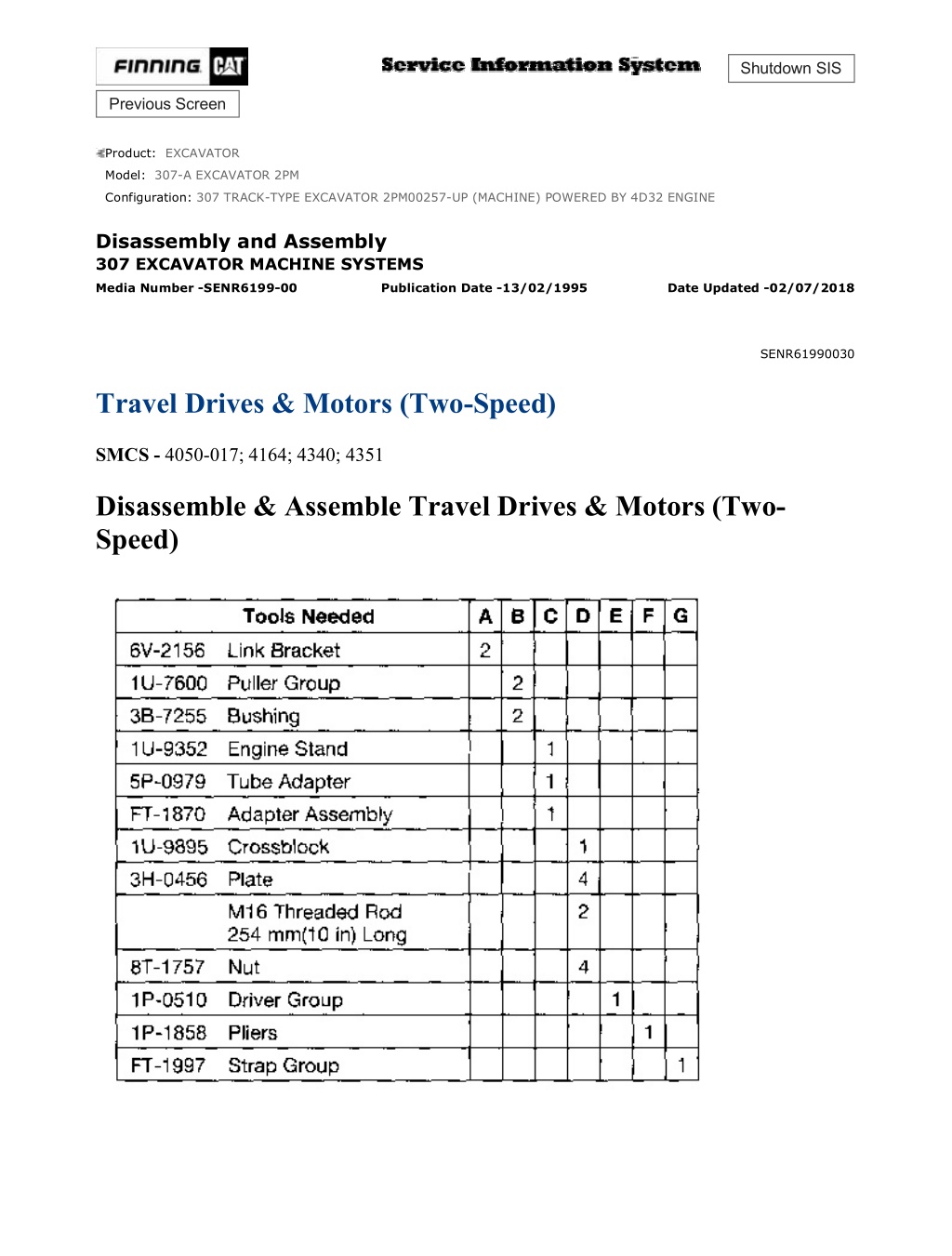
w 1/31(W) Shutdown SIS Previous Screen Product: EXCAVATOR Model: 307-A EXCAVATOR 2PM Configuration: 307 TRACK-TYPE EXCAVATOR 2PM00257-UP (MACHINE) POWERED BY 4D32 ENGINE Disassembly and Assembly 307 EXCAVATOR MACHINE SYSTEMS Media Number -SENR6199-00 Publication Date -13/02/1995 Date Updated -02/07/2018 SENR61990030 Travel Drives & Motors (Two-Speed) SMCS - 4050-017; 4164; 4340; 4351 Disassemble & Assemble Travel Drives & Motors (Two- Speed) https://127.0.0.1/sisweb/sisweb/techdoc/techdoc_print_page.jsp?returnurl=/sisweb/sis... 2021/12/26
w 2/31(W) Start By: a. remove travel drives and motors NOTE: During disassembly, put identification marks on all parts of the travel drive and motor for assembly purposes. NOTICE The travel drive and motor will be rotated using Tooling (C) during disassembly and assembly. Be sure the travel drive and motor is centered properly in Tooling (C) when it is mounted for correct balancing. 1. Fasten Tool (A) and a hoist to travel drive and motor (1) as shown. The weight of the travel drive and motor is 118 kg (260 lb). Fasten the travel drive and motor to Tooling (C) as shown. Drain the oil from the travel drive and motor into a suitable container for storage or disposal. The capacity of the final drive is 3.4 liters (.9 U.S. gal). https://127.0.0.1/sisweb/sisweb/techdoc/techdoc_print_page.jsp?returnurl=/sisweb/sis... 2021/12/26
w 3/31(W) 2. Using a .010 to .015 in feeler gauge, remove ring (2) from the groove between cover (4) and travel drive housing (3). 3. Remove the fill and drain plugs from cover (4) of the travel drive. Install a 3B-7255 Bushing [part of Tooling (B)] in each threaded hold in the cover. Fasten a 1U-7600 Puller Group to each bushing as shown. Carefully remove cover (4) from the housing. 4. Remove O-ring seal (5) from cover (4). 5. Remove gear assembly (8) from the travel drive. 6. Using Tool (F), remove three retaining rings (6). Remove three gears (7) from the shafts. https://127.0.0.1/sisweb/sisweb/techdoc/techdoc_print_page.jsp?returnurl=/sisweb/sis... 2021/12/26
https://www.ebooklibonline.com Hello dear friend! Thank you very much for reading. Enter the link into your browser. The full manual is available for immediate download. https://www.ebooklibonline.com
w 4/31(W) 7. Remove spacers (9) from each shaft. 8. Disassemble gear assembly (8). Remove ball (10) from the end of shaft (13). Using Tool (F), remove retaining ring (11). Remove gear (12) from shaft (13). 9. Remove coupling (14) from the flange plate in the travel drive. 10. Using Tooling (C), turn the travel drive and motor over as shown. 11. Remove four socket head bolts (15) and surge cut valve (16). 12. Remove four fittings (18) from the cover assembly. 13. Remove eight socket head bolts (19). Carefully remove cover assembly (17) from the travel drive housing. 14. Disassemble surge cut valve (16) as follows: https://127.0.0.1/sisweb/sisweb/techdoc/techdoc_print_page.jsp?returnurl=/sisweb/sis... 2021/12/26
w 5/31(W) a. Remove plug (25), spring (23), spring (22), stopper (21) and spool (20) from the valve body. b. Remove O-ring seal (24) from plug (25). 15. Disassemble cover assembly (17) as follows: a. Remove eight springs (26) from the cover assembly. b. Mark the position of timing plate (27) in relation to the cover assembly for installation purposes. Remove timing plate (27) from the cover assembly. https://127.0.0.1/sisweb/sisweb/techdoc/techdoc_print_page.jsp?returnurl=/sisweb/sis... 2021/12/26
w 6/31(W) c. Remove bearing (28) from the cover assembly. d. Remove two dowels (29) from the cover assembly. e. Remove and disassemble brake pilot valve (30). Using a small diameter steel rod, push down on seat (32). While hold pressure on the seat, remove retaining ring (31) with a seal pick. Remove seat (32), spring (33) and valve (34) from the rear flange. Remove O-ring seal (35) from the seat. f. Remove three O-ring seals (39) and plug (36) from the cover. g. Remove and disassemble displacement change valve (37). Remove the plug, spool assembly (43) and spring (42). Remove O-ring seal (44) from the plug. h. Remove and disassemble two check valves (38). Remove the two plugs and two balls (40). Remove O-ring seal (41) from each plug. https://127.0.0.1/sisweb/sisweb/techdoc/techdoc_print_page.jsp?returnurl=/sisweb/sis... 2021/12/26
w 7/31(W) i. Remove and disassemble the counterbalance valve. Remove plugs (53) and (62). Remove springs (49) and (60). Remove seats (47) and (58). Remove spool (55). Remove O-ring seal (51) from plug (53). Remove O-ring seal (61) from plug (62). j. Remove and disassemble the two check valves. Remove plugs (52) and (59). Remove springs (48) and (56). Remove valves (46) and (54). Remove O-ring seal (50) from plug (52). Remove O- ring seal (57) from plug (59). 16. Remove two dowels (63) from the spindle. 17. Remove two O-ring seals (64) from the spindle. Piston (66) must be removed from the spindle with shop air. The piston can come out of the spindle with force during the removal procedure. To prevent possible personal injury, install Tool (D) as shown. Tool (D) will retain the piston in the spindle when applying shop air pressure. https://127.0.0.1/sisweb/sisweb/techdoc/techdoc_print_page.jsp?returnurl=/sisweb/sis... 2021/12/26
w 8/31(W) 18. Fasten Tool (D) to the spindle as shown. Apply shop air pressure (free of water) of approximately 525 kPa (75 psi) to release port (65). The piston will move up and out of the bore in the spindle. Remove Tool (D) and piston (66) from the spindle. 19. Remove two O-ring seals (67) and two back-up rings (68) from piston (66). 20. Using a seal pick, remove two separator plates (69) and two friction plates (70). NOTICE During removal of the barrel assembly from the spindle, do not let the components come apart. All parts in the barrel assembly should be installed in their original location. https://127.0.0.1/sisweb/sisweb/techdoc/techdoc_print_page.jsp?returnurl=/sisweb/sis... 2021/12/26
w 9/31(W) 21. Using Tooling (C), turn the travel drive housing and spindle on its side as shown. Carefully remove the barrel assembly from the shaft. 22. Disassemble the barrel assembly as follows: a. Put identification marks on nine piston assemblies (72) as to their location in retainer plate (73) and barrel (71). Remove nine piston assemblies (72) and retainer plate (73), as a unit, from barrel (71). Separate the piston assemblies from the retainer plate. b. Remove guide (74) and three pins (75) from barrel (71). https://127.0.0.1/sisweb/sisweb/techdoc/techdoc_print_page.jsp?returnurl=/sisweb/sis... 2021/12/26
w 10/31(W) There is spring force against washer (77). When retaining ring (76) is removed the spring force will be released. To prevent possible personal injury, removal of the internal components in barrel (71) should be performed in a press in order to retain spring (78) and washer (77). NOTE: Washers (77) and (79) are the same and can be interchanged. c. Put barrel (71) in a press. Install Tool (E) on washer (77). Put a slight amount of compression on washer (77). Use Tool (F) to remove retaining ring (76). Slowly release the spring compression. Remove washer (77), spring (78) and washer (79) from barrel (71). 23. Using Tooling (C), turn the travel drive housing and spindle so the spindle is facing up as shown. Remove shaft assembly (80) and swashplate (81), as a unit, from the spindle. If may be necessary to use a soft faced hammer to remove the components. Tap the shaft from the opposite side to free it. 24. Remove swashplate (81) from shaft assembly (80). 25. Remove plate (82) from swahsplate (81). 26. Disassemble shaft assembly (80) as follows: https://127.0.0.1/sisweb/sisweb/techdoc/techdoc_print_page.jsp?returnurl=/sisweb/sis... 2021/12/26
w 11/31(W) a. Put shaft assembly (80) in a press. Using Tool (E) and the press, push shaft (83) out of bearing (84). 27. Remove piston assembly (85) and spring (87) located under the piston assembly. 28. Remove two pivots (86) and two dowels (88). A dowel is located under each pivot. 29. Remove lip-type seal (89) from the spindle. https://127.0.0.1/sisweb/sisweb/techdoc/techdoc_print_page.jsp?returnurl=/sisweb/sis... 2021/12/26
w 12/31(W) NOTE: Spindle (90) slides into travel drive housing (91). Tooling (G) is used to hold the two components together. 30. Install Tooling (G) over spindle (90), and fasten it to travel drive housing (91) as shown. 31. Using Tooling (C), turn the travel drive housing and spindle over as shown. 32. Put identification marks on three shaft assemblies (94), three retaining rings (93) and three bearings (96) as to their location in flange plate (95). Also, identify the position of a spline tooth on each shaft assembly for reassembly purposes. NOTICE The thread lock compound used on reamer bolts (92) may cause the bolts to seize during removal. The reamer bolts should be slowly removed by hand. Do not use an impact wrench to remove the reamer bolts. If the reamer bolts will no longer turn during the removal procedure, do not use force to complete the removal. Instead, re- tighten the bolts; then try loosening them again. 33. Carefully remove three reamer bolts (92). https://127.0.0.1/sisweb/sisweb/techdoc/techdoc_print_page.jsp?returnurl=/sisweb/sis... 2021/12/26
w 13/31(W) 34. Use Tool (H) to remove flange plate (95) from the travel drive housing. 35. Use Tool (J) to remove three retaining rings (97) from flange plate (95). 36. Remove three bearing cups (98) from flange plate (95). The bearing cups are a slip fit. 37. Using Tooling (C), turn the travel drive housing and spindle over as shown. NOTICE Duo-Cone seal (99) can fall out of spindle (90) when the spindle is removed from travel drive housing (91). Carefully remove the spindle from the travel drive housing so the Duo-Cone seal does not fall out of place. 38. Remove Tooling (G) from over spindle (90). Fasten Tool (K) and a hoist to spindle (90). Carefully remove spindle (90) from travel drive housing (91). The weight of the spindle is 23 kg (50 lb). https://127.0.0.1/sisweb/sisweb/techdoc/techdoc_print_page.jsp?returnurl=/sisweb/sis... 2021/12/26
w 14/31(W) 39. Remove Duo-Cone seal (99) from spindle (90). Remove three bearing cups (100) from the spindle. 40. Remove retainer (101) from the travel drive housing. The retainer is a slip fit. 41. Using a seal pick, carefully remove O-ring seal (102) from the travel drive housing. 42. Use a hammer and a brass punch to remove bearing (103) from the travel drive housing. 43. Remove collar (104) from the travel drive housing. The collar is a slip fit. https://127.0.0.1/sisweb/sisweb/techdoc/techdoc_print_page.jsp?returnurl=/sisweb/sis... 2021/12/26
w 15/31(W) NOTE: Gear kit (107) consists of two gear plates (105) and (108) and three shaft assemblies (106). 44. Identify the orientation of three shaft assemblies (106) in relation to gear plate (105). The orientation marks should match the marks made on gear plate (108). 45. Put a suitable container under the travel drive housing. Rollers (109) may fall out of the travel drive housing when gear kit (107) is removed. Remove gear kit (107). 46. Remove 24 rollers (109) from the travel drive housing. 47. Use hammer and a brass punch to remove bearing (110) from the travel drive housing. 48. Disassemble gear kit (107) as follows: https://127.0.0.1/sisweb/sisweb/techdoc/techdoc_print_page.jsp?returnurl=/sisweb/sis... 2021/12/26
w 16/31(W) a. Separate gear plates (105) and (108) from three shaft assemblies (106). b. Disassemble the three shaft assemblies. Remove bearing cones (112) and (115) from shaft (111). Remove two bearings (113) and (114) from shaft (111). NOTE: The following steps are for the assembly of the travel drive and motor. NOTICE Malfunction or premature failure of the travel motor portion of the travel drive assembly will result if the travel drive assembly is not assembled properly. Adjustment of bearing (110) end play is required when either travel drive housing (91), flange plate (95) and/or gear plate (105) is replaced. For proper bearing end play adjustment, see the topic "Travel Motor And Drive" in the 307 Excavators Hydraulic System Specifications module, SENR6194. 49. Check the condition of all parts used in the travel drive and motor for wear or damage. If any of the parts are worn or damaged, use new parts for replacement. Be sure all parts are thoroughly clean prior to assembly. 50. Assemble gear kit (107) as follows: a. Heat bearings (113) and (114), and install them on shaft (111). Seat the bearings against the shoulder on the shaft. b. Heat bearing cones (112) and (115). Install the bearing cones on shaft (111). Seat the bearing cones against the bearings. https://127.0.0.1/sisweb/sisweb/techdoc/techdoc_print_page.jsp?returnurl=/sisweb/sis... 2021/12/26
w 17/31(W) c. Install three shaft assemblies (106) in gear plate (105) in their original locations. Position the spline of each shaft assembly in its original identified location. NOTE: There is a single mark (116) on gear plate (105). There are two marks on gear plate (108). The holes next to these marks match. The marks face outward away from each other. d. Install gear plate (108) in its original position. NOTE: Gear kit (107) can be tied together until time for installation. 51. Install collar (104) in travel drive housing (91). The collar is a slip fit. 52. Using a hammer and a brass punch, install bearing (103) in the travel drive housing with the inner race facing out as shown. https://127.0.0.1/sisweb/sisweb/techdoc/techdoc_print_page.jsp?returnurl=/sisweb/sis... 2021/12/26
w 18/31(W) 53. Install O-ring seal (102) in the travel drive housing as shown. 54. Apply 1U-6396 O-ring Assembly Compound on retainer (101). Install retainer (101) in the travel drive housing. The retainer is a slip fit. 55. Install three bearing cups (100) in the spindle. It may be necessary to use a brass punch and a hammer to seat the bearing cups properly in the spindle. NOTICE See the topic "Assembly And Installation Of Conventional Duo-Cone Seals" in this module. NOTE: The rubber seals and all surfaces that make contact with the seals must be clean and dry. After installation of the seals, put clean SAE 30 oil on the contact surfaces of the metal seals. https://127.0.0.1/sisweb/sisweb/techdoc/techdoc_print_page.jsp?returnurl=/sisweb/sis... 2021/12/26
w 19/31(W) 56. Using Tool (L), install Duo-Cone seal (99) in spindle (90). NOTICE Duo-Cone seal (99) can fall out of spindle (90) when the spindle is installed in travel drive housing (91). Carefully install the spindle in the travel drive housing so the Duo-Cone seal does not fall out of place. 57. Carefully turn spindle (90) over. Fasten Tool (J) and a hoist to the spindle as shown. Carefully install spindle (90) in travel drive housing (91). 58. Using Tool (E), install lip-type seal (89) in the spindle. Install the seal until it makes contact with the counterbore in the spindle and with the lip facing toward the outside of the spindle (side opposite the travel drive). https://127.0.0.1/sisweb/sisweb/techdoc/techdoc_print_page.jsp?returnurl=/sisweb/sis... 2021/12/26
w 20/31(W) 59. Install Tooling (G) over spindle (90), and fasten it to travel drive housing (91) as shown. Tooling (G) will keep the components together. 60. Using Tooling (C), turn the spindle and travel drive housing over as shown. 61. Install gear kit (107) in the travel drive housing as shown. Be sure the gear kit is seated against the bearing in the travel drive housing. 62. Install 24 rollers (109) in the travel drive housing. 63. Using a hammer and a brass punch, install bearing (110) in the travel drive housing with the inner race facing out as shown. https://127.0.0.1/sisweb/sisweb/techdoc/techdoc_print_page.jsp?returnurl=/sisweb/sis... 2021/12/26
w 21/31(W) 64. Install three bearing cups (98) in flange plate (95). Install each bearing cup until they it is even with the retaining ring groove in the flange plate. 65. Install flange plate (95) in bearing (110) and over the appropriate shaft assemblies. Be sure the flange plate is installed straight. If the flange plate is not straight, reamer bolts (92) will seize during installation. 66. Apply 5P-3931 Anti-Seize Compound on the reamer portion of three reamer bolts (92). Apply 9S-3263 Thread Lock on the threads of three reamer bolts (92). Install the three reamer bolts, and evenly tighten them to a torque of 412 64 N m (310 48 lb ft). 67. Use a hammer and a brass punch to properly seat three bearing cups (98). https://127.0.0.1/sisweb/sisweb/techdoc/techdoc_print_page.jsp?returnurl=/sisweb/sis... 2021/12/26
w 22/31(W) NOTE: Adjustment of bearing (112) end play is required when either travel drive housing (91), flange plate (95), spindle (90) and/or gear plate (105) is replaced. See the topic "Travel Motor And Drive" in the 307 Excavator Hydraulic System Specifications module, SENR6194. 68. Using Tool (J), install three retaining rings (97). 69. Use a hammer and a brass punch to properly seat three retaining rings (97). 70. Assemble the barrel assembly as follows: NOTE: Washers (77) and (79) are the same and can be interchanged. a. Install washer (79), spring (78) and washer (77) in barrel (71). Put the barrel in a press. Install Tool (E) on washer (77). Using Tool (E) and the press, compress spring (78) until retaining ring (76) can be installed. Use Tool (F) to install the retaining ring. b. Install three pins (75) and guide (74) on barrel (71). https://127.0.0.1/sisweb/sisweb/techdoc/techdoc_print_page.jsp?returnurl=/sisweb/sis... 2021/12/26
w 23/31(W) c. Put clean hydraulic oil on nine piston assemblies (72). Install the piston assemblies in their original bores in plate (73). Install the plate with the piston assemblies in their original bores in barrel (71). 71. Assemble shaft assembly (80). Using a press, install shaft (83) in bearing (84). 72. Install plate (82) in swashplate (81). The rounded edge on plate (82) must face toward the swashplate. https://127.0.0.1/sisweb/sisweb/techdoc/techdoc_print_page.jsp?returnurl=/sisweb/sis... 2021/12/26
w 24/31(W) 73. Install spring (87) in the spindle. Apply Loctite LB 8632 Silicone Lubricant (North America), Loctite LB 8104 Silicone Lubricant (EAME), Loctite LB 8801 Silicone Lubricant (Asia Pacific Division), or Loctite LB Superlube (South America) on piston assembly (85). Install the piston assembly in the spindle. 74. Apply Loctite LB 8632 Silicone Lubricant (North America), Loctite LB 8104 Silicone Lubricant (EAME), Loctite LB 8801 Silicone Lubricant (Asia Pacific Division), or Loctite LB Superlube (South America) in two dowels (88) and two pivots (86). Install two dowels (88) and two pivots (86) in the spindle. 75. Put swashplate (81) on shaft assembly (80). Install the shaft assembly and swashplate, as a unit, in spindle (90). Be sure two pivots (86) fit in the indentations in the bottom of the swashplate properly. NOTICE Do not let the components of the barrel assembly fall apart when it is installed in the spindle. https://127.0.0.1/sisweb/sisweb/techdoc/techdoc_print_page.jsp?returnurl=/sisweb/sis... 2021/12/26
Suggest: If the above button click is invalid. Please download this document first, and then click the above link to download the complete manual. Thank you so much for reading
w 25/31(W) 76. Using Tooling (C), turn the spindle and travel drive housing on its side as shown. Carefully install the barrel assembly in the spindle. 77. Using Tooling (C), turn the spindle and travel drive housing in the position shown. Install two friction plates (70) and two separator plates (69) in the spindle in alternating order. Start with a friction plate and end with a separator plate. Be sure the top separator plate is above the shoulder in the spindle as shown. 78. Install two back-up rings (68) and two O-ring seals (67) on piston (66) in the positions shown. Apply clean hydraulic oil on the O-ring seals and back-up rings. 79. Install piston (66) in the spindle. Be sure the piston is seated properly in the spindle. If necessary, use a soft faced hammer to install the piston. https://127.0.0.1/sisweb/sisweb/techdoc/techdoc_print_page.jsp?returnurl=/sisweb/sis... 2021/12/26
https://www.ebooklibonline.com Hello dear friend! Thank you very much for reading. Enter the link into your browser. The full manual is available for immediate download. https://www.ebooklibonline.com