Caterpillar Cat D6H and D6H LGP SERIES II TRACTOR (Prefix 1KD) Service Repair Manual Instant Download (1KD04074 and up)
Please open the website below to get the complete manualnn// n

Download Presentation

Please find below an Image/Link to download the presentation.
The content on the website is provided AS IS for your information and personal use only. It may not be sold, licensed, or shared on other websites without obtaining consent from the author. Download presentation by click this link. If you encounter any issues during the download, it is possible that the publisher has removed the file from their server.
E N D
Presentation Transcript
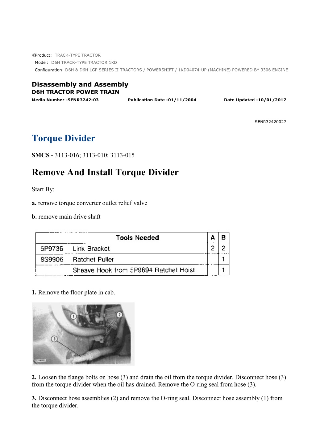
w 1/17(W) Product: TRACK-TYPE TRACTOR Model: D6H TRACK-TYPE TRACTOR 1KD Configuration: D6H & D6H LGP SERIES II TRACTORS / POWERSHIFT / 1KD04074-UP (MACHINE) POWERED BY 3306 ENGINE Disassembly and Assembly D6H TRACTOR POWER TRAIN Media Number -SENR3242-03 Publication Date -01/11/2004 Date Updated -10/01/2017 SENR32420027 Torque Divider SMCS - 3113-016; 3113-010; 3113-015 Remove And Install Torque Divider Start By: a. remove torque converter outlet relief valve b. remove main drive shaft 1. Remove the floor plate in cab. 2. Loosen the flange bolts on hose (3) and drain the oil from the torque divider. Disconnect hose (3) from the torque divider when the oil has drained. Remove the O-ring seal from hose (3). 3. Disconnect hose assemblies (2) and remove the O-ring seal. Disconnect hose assembly (1) from the torque divider. https://127.0.0.1/sisweb/sisweb/techdoc/techdoc_print_page.jsp?returnurl=/sisweb/siswe... 2022/2/4
w 2/17(W) 4. Remove elbow (5) from the bottom of the flywheel housing. Remove the O-ring seal from elbow (5). 5. Remove sleeve (4). Remove two O-ring seals from sleeve (4). 6. The weight of the torque divider is 145 kg (320 lb). Install tooling (A) onto the torque divider. 7. Install tooling (B) to the ceiling of the cab, as shown. Attach tooling (B) to tooling (A). 8. Remove the twelve bolts that fasten the torque divider to the flywheel housing. Separate the torque divider from the flywheel housing. Use tooling (B) and lower the torque divider to the ground. 9. Remove the large O-ring seal from the torque divider housing. https://127.0.0.1/sisweb/sisweb/techdoc/techdoc_print_page.jsp?returnurl=/sisweb/siswe... 2022/2/4
w 3/17(W) NOTE: The following steps are for installation of the torque divider. 10. Install the O-ring seal onto the torque divider housing. 11. Use tooling (A), tooling (B), and two 3/8" guide bolts and put the torque divider in position on the flywheel housing. 12. Make sure the teeth are aligned with the flywheel, and install the twelve bolts that hold the torque divider to the flywheel housing. Remove tooling (A) and (B). 13. Install the O-ring seals onto sleeve (4) and elbow (5). Install the sleeve and elbow onto the bottom of the torque divider. 14. Put the O-ring seal in position on hose assemblies (2). Connect hose assemblies (2) and (1) to the torque divider. 15. Put the O-ring seal in position on hose assembly (3) and connect it to the torque divider housing. 16. Install the floor plate in cab. 17. Check the power train oil level and add as necessary. See the Operation and Maintenance Guide for the type of oil and capacity. End By: a. install torque converter outlet relief valve b. install main drive shaft Disassemble Torque Divider Start By: a. remove torque divider NOTICE https://127.0.0.1/sisweb/sisweb/techdoc/techdoc_print_page.jsp?returnurl=/sisweb/siswe... 2022/2/4
https://www.ebooklibonline.com Hello dear friend! Thank you very much for reading. Enter the link into your browser. The full manual is available for immediate download. https://www.ebooklibonline.com
w 4/17(W) When a torque converter or divider has a failure, the complete oil system for the torque converter, torque divider and transmission must be thoroughly cleaned. Any foreign material which is not removed from the oil system for the torque converter will move through the hydraulic system for the transmission. 1. Use tool (A), and remove retaining ring (1) from the shaft. 2. Remove planetary carrier (2). 3. Remove retainer (4) and retaining ring (3) from the planetary carrier. 4. Use a hammer and a punch to push pin (8) into shaft (7). 5. Remove shaft (7), two washers (9) and gear (6). https://127.0.0.1/sisweb/sisweb/techdoc/techdoc_print_page.jsp?returnurl=/sisweb/siswe... 2022/2/4
w 5/17(W) 6. Remove bearings (5) from the gear. 7. Remove the pin from shaft (7). 8. Remove the bolt, retainer, O-ring seal and yoke. 9. Put wood blocks under the converter group, as shown, so the cover can be removed. 10. Remove eight bolts (10). 11. The weight of cover (12) is 68 kg (150 lb). Install tooling (B), and attach a hoist. Install two 3/8 "-16 NC forcing screws (11) in the cover. Tighten the forcing screws evenly, and remove cover (12). 12. Remove O-ring seal (14) and lip-type seal (13). https://127.0.0.1/sisweb/sisweb/techdoc/techdoc_print_page.jsp?returnurl=/sisweb/siswe... 2022/2/4
w 6/17(W) 13. Remove two bolts (15) and washers 180 apart from each other. Drain the oil from the converter. 14. Use tool (C), and remove retaining ring (17). 15. Remove shaft assembly (16) and the bearing. 16. Remove seal ring (21) from shaft assembly (19). 17. Remove bearing (20) from the shaft assembly. NOTE: Race (18) will be destroyed if it is removed from the shaft assembly. 18. Remove race (18) from the shaft assembly if necessary. 19. Remove the remaining thirty-four bolts (15) and washers. Install two 3/8 "-16 NC forcing screws (23) into impeller wheel (22). 20. The weight of impeller wheel (22) and the carrier assembly is 30 kg (66 lb). Install tooling (D), and attach a hoist. Tighten two forcing screws (23) evenly, and remove the impeller wheel and carrier assembly. NOTICE Use care to avoid causing damage to the stator when it is removed. https://127.0.0.1/sisweb/sisweb/techdoc/techdoc_print_page.jsp?returnurl=/sisweb/siswe... 2022/2/4
w 7/17(W) 21. Remov eight bolts (24), and remove stator assembly (25). 22. Support the wheel and carrier assembly as close to the center as possible with wood blocks. Use tooling (E) on the inside diameter of pins (26), and remove carrier (27). 23. Remove seal ring (28) and pins (26) from the carrier. 24. Remove the eight bolts that fasten retainer (29) to the impeller wheel. Use two 3/8 "-24 NF forcing screws, and remove retainer (29). 25. Use tool (F), and remove carrier (30) and the bearing. 26. Use tool (F), and remove bearing (31) from carrier (30). https://127.0.0.1/sisweb/sisweb/techdoc/techdoc_print_page.jsp?returnurl=/sisweb/siswe... 2022/2/4
w 8/17(W) 27. Use tool (G), and remove retaining ring (33) from the flange. 28. Remove turbine wheel (32) from housing (34) and the flange assembly. Remove the spacer that is under turbine wheel (32). 29. The weight of the housing with gear and flange assembly is 35.5 kg (78 lb). Turn the housing over, and remove two stop pins (35). 30. Compress the retaining ring, and remove gear (36). Remove the retaining ring. 31. Install two 3/8 "-16 NC forcing screws in flange assembly (37). Tighten the forcing screws evenly, and remove flange assembly (37) from the housing. 32. Remove seal (40) from carrier (39) on flange assembly (37). NOTE: Carrier (39) will be destroyed if it is removed from the flange assembly. https://127.0.0.1/sisweb/sisweb/techdoc/techdoc_print_page.jsp?returnurl=/sisweb/siswe... 2022/2/4
w 9/17(W) 33. If carrier (39) is to be removed, use a chisel to break the carrier, and remove it. 34. Use tooling (E), and remove two bearings (38) from flange assembly (37). 35. Remove the six bolts and retainer (41) from the housing. 36. Use tooling (F), and remove bearing (42) from housing (34). Assemble Torque Divider NOTE: Before the torque divider is assembled, measurements of certain clearances must be made if the torque divider is to operate with efficiency. 1. Check the clearance between the turbine wheel and stator as follows: https://127.0.0.1/sisweb/sisweb/techdoc/techdoc_print_page.jsp?returnurl=/sisweb/siswe... 2022/2/4
w 10/17(W) a. Put stator (3) in position in turbine wheel (2). Hold the stator against one side of the turbine wheel, and use a feeler gauge (1) to find the clearance between the stator and the turbine wheel. b. The clearance across the diameters between the stator and the turbine wheel must be 0.33 to 0.43 mm (.013 ot .017 in). Check the clearance at four points on the turbine wheel. The maximum permissible clearance across the diameters is 0.76 mm (.030 in). c. The running clearance is one half of the clearance across the diameters between the stator and the turbine wheel. The running clearance must be 0.165 to 0.215 mm (.0065 to .0085 in). The maximum permissible running clearance is 0.38 mm (.015 in). 2. Check the clearance between the impeller wheel and stator as follows. a. Use an outside diameter micrometer (4), and make a measurement of the diameter of the stator flange at four points on stator. Make a record of the lowest reading. b. Use an inside diameter micrometer (6), and make a measurement of the inside diameter of outer edge of flange on impeller wheel (5) at four points. Make a record of the highest reading. c. The clearance across the diameters between the impeller and stator is the difference between the highest reading on impeller and the lowest reading on stator. The clearance must be 0.25 to 0.35 mm (.010 to .014 in). Maximum permissible clearance across the diameters is 0.61 mm (.024 in). d. The running clearance is one half of the measurement made across the diameters. Running clearance must be 0.125 to 0.175 mm (.005 to .007 in). Maximum permissible running clearance is 0.30 mm (.012 in). https://127.0.0.1/sisweb/sisweb/techdoc/techdoc_print_page.jsp?returnurl=/sisweb/siswe... 2022/2/4
w 11/17(W) 3. Use tooling (A), and install bearing (7) into housing (8). 4. Put retainer (10) in position on the housing, and install six bolts (9). Tighten bolts (9) to a torque of 50 7 N m (37 5 lb ft). 5. Use tooling (B), and install two bearings (12) and (13) in flange assembly (11). a. Bearing (12) should be installed to a depth of 25.4 mm (1.0 in) below the surface of flange assembly (11). b. Bearing (13) should be installed flush with the surface of flange assembly (11). c. Bearings (12) and (13) should have an inside diameter of 44.501 0.013 mm (1.7520 .0005 in) after installation. https://127.0.0.1/sisweb/sisweb/techdoc/techdoc_print_page.jsp?returnurl=/sisweb/siswe... 2022/2/4
w 12/17(W) 6. If carrier (14) was removed from flange assembly (11), heat the carrier to a temperature of 138 C to 166 C (280 F to 330 F) for a maximum time of ten minutes. Install carrier (14) on flange assembly (11). Install seal ring (15) on the carrier. NOTICE When the flange assembly is installed into the housing, use care to avoid causing damage to seal ring (15). 7. Put SAE 30 oil on seal ring (15). Pull the ends of the seal ring together, and install flange assembly (11) into housing (8). 8. Put retaining ring (17) in position in the groove on flange assembly (11). Compress the ring, and install gear (18). Make sure retaining ring (17) engages the slot in gear (18) to hold it into position. 9. Install two pins (16) to hold the retaining ring in position. 10. Hold gear (18) and flange assembly (11) to prevent them from sliding, and turn housing (8) over. Put spacer (21) in position on the flange assembly. 11. Install turbine wheel (20) onto the flange assembly. 12. Use tool (C), and install retaining ring (19) onto the flange assembly. https://127.0.0.1/sisweb/sisweb/techdoc/techdoc_print_page.jsp?returnurl=/sisweb/siswe... 2022/2/4
w 13/17(W) 13. Use tooling (A), and install bearing (23) into carrier (22). 14. Use two 3/8 " - 24 NF guide bolts, and put carrier (22) in position in impeller wheel (24). Use tooling (A), and install carrier. 15. Turn impeller wheel (24) over, and put the retainer in position. Install eight bolts (25), and tighten to a torque of 50 7 N m (37 5 lb ft). https://127.0.0.1/sisweb/sisweb/techdoc/techdoc_print_page.jsp?returnurl=/sisweb/siswe... 2022/2/4
w 14/17(W) 16. Install six pins (26) into carrier (27). 17. Install seal ring (28) onto the carrier. NOTICE When the carrier is installed into the impeller wheel, use care to avoid causing damage to seal ring (28). 18. Put SAE 30 oil on seal ring (28). Pull the ends of the seal ring together, and put carrier (27) into position on the impeller wheel. 19. Use tooling (A), and install carrier (27) into impeller wheel (24). 20. Turn the impeller wheel over, and install two 3/8" guide bolts. Put stator (29) in position, and install the eight bolts. Tighten the eight bolts evenly to a torque of 30 5 N m (22 4 lb ft). 21. Turn the impeller wheel over. Install tooling (E) onto impeller wheel (24) and the carrier, and attach a hoist. Put the impeller wheel and carrier in position on housing (8). Remove tooling (E), and install the thirty-six bolts. Tighten the thirty-six bolts to a torque of 30 5 N m (22 4 lb ft). 22. Heat race (30) to a temperature of 135 C (275 F) for a maximum time of ten minutes, and install the race onto shaft assembly (31). https://127.0.0.1/sisweb/sisweb/techdoc/techdoc_print_page.jsp?returnurl=/sisweb/siswe... 2022/2/4
w 15/17(W) 23. Install seal ring (33) onto the shaft assembly. 24. Heat bearing (32) to a temperature of 135 C (275 F) for a maximum time of ten minutes. Install bearing (32) onto the shaft assembly. NOTICE When the shaft assembly is installed into the converter group, use care to avoid causing damage to seal ring (33). 25. Put SAE 30 oil on seal ring (33). Pull the ends of the seal ring together, and install shaft assembly (31) and the bearing into the converter group. 26. Use tool (F), and install retaining ring (34). 27. Install O-ring seal (36) onto carrier (27). Put SAE 30 oil on the seal. 28. Install lip-type seal (35) into the carrier with the lip of the seal toward the bearing. Put SAE 30 oil on the lip of the seal. 29. Install tooling (E) onto cover (37), and attach a hoist. 30. Use two 3/8 " - 24 NF guide bolts, and install cover (37) onto the converter group. Make sure O-ring seal (36) stays in position when the cover is installed. https://127.0.0.1/sisweb/sisweb/techdoc/techdoc_print_page.jsp?returnurl=/sisweb/siswe... 2022/2/4
w 16/17(W) 31. Install eight bolts (42), and tighten to a torque of 54 3 N m (40 2 lb ft). 32. Install yoke (41). Install retainer (39) and bolt (38). Tighten bolt (38) to a torque of 47 9 N m (34 6 lb ft). 33. Put bearing (43) in gear (44). Put gear (44) and one disc (47) on each side of the gear in position in the carrier, and install shaft (45). 34. Align the hole in shaft (45) with the hole in the carrier, and install pin (46) flush with the surface of the carrier. 35. Install spiral ring (49) into the inner diameter of carrier (48). Put retainer (50) in position next to the spiral ring. https://127.0.0.1/sisweb/sisweb/techdoc/techdoc_print_page.jsp?returnurl=/sisweb/siswe... 2022/2/4
Our support email: ebooklibonline@outlook.com
https://www.ebooklibonline.com Hello dear friend! Thank you very much for reading. Enter the link into your browser. The full manual is available for immediate download. https://www.ebooklibonline.com