Overview of Aquaflair and Uniflair Chillers
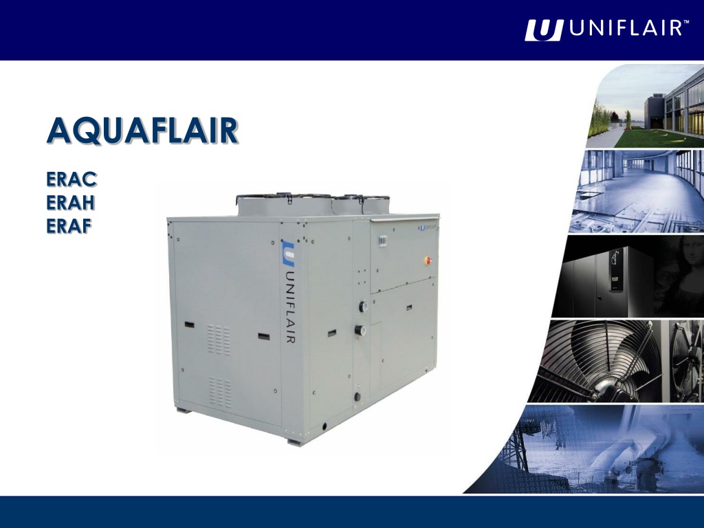


AQUAFLAIR
AQUAFLAIR
ERAC
ERAC
ERAH
ERAH
ERAF
ERAF


L
R
A
6
-
4
0
k
W
E
R
A
-
I
S
A
5
0
-
1
1
0
k
W
A
R
A
1
0
0
-
2
6
0
k
W
B
R
E
4
0
0
-
1
2
0
0
k
W
B
C
W
3
0
0
-
1
2
5
0
k
W
B
R
W
3
0
0
-
1
2
0
0
k
W
UNIFLAIR CHILLERS
UNIFLAIR CHILLERS
OVERVIEW
Product Range
R
e
f
r
i
g
e
r
a
n
t
:
R
4
1
0
A
C
o
o
l
i
n
g
C
a
p
a
c
i
t
y
:
5
0
–
1
1
0
k
W
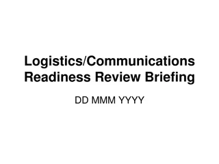
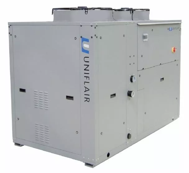
ERAC
Air-Cooled Water Chiller with Axial Fans
ERAH
Air / Water Heat Pump with Axial Fans
ERAF
Air-Cooled Water Chillers with Axial Fans and Free-Cooling System
The new ERAC chillers, ERAH heat pumps and ERAF units with free-
cooling system, feature state-of-the-art technology ensuring maximum
reliability, safety, quiet operation and respect for the environment.
ERA-C C/F/H
ERA-C C/F/H
OVERVIEW OF THE UNIT
ERA-C C/F/H
ERA-C C/F/H
OVERVIEW OF THE UNIT
60
70
80
90
40
50
100
110
120
0521A
0621A
0721A
0821A
0921A
1021A
1221A
kW
0922A
1022A
1222A
ERA-C C/F/H
ERA-C C/F/H
OVERVIEW OF THE UNIT
ERA-C C/F/H
ERA-C C/F/H
OVERVIEW OF THE UNIT
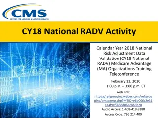
Free-cooling
ERAF
Axial fans
Heat pump
ERAH
Cooling only
ERAC
ERA C/F/H
ERA C/F/H
OVERVIEW OF THE UNIT
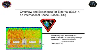
Free-cooling
ERCF
Ducted fans
Heat pump
ERCH
Cooling only
ERCC
ERC C/F/H
ERC C/F/H
OVERVIEW OF THE UNIT
T
h
e
A
Q
U
A
F
L
A
I
R
E
R
A
C
/
H
/
F
s
e
r
i
e
s
i
s
c
o
m
p
o
s
e
d
o
f
t
e
n
c
h
i
l
l
e
r
s
w
i
t
h
n
o
m
i
n
a
l
c
o
o
l
i
n
g
c
a
p
a
c
i
t
i
e
s
r
a
n
g
i
n
g
f
r
o
m
5
0
t
o
1
1
0
k
W
.
T
h
e
v
a
r
i
o
u
s
v
e
r
s
i
o
n
s
c
a
n
b
e
m
a
n
a
g
e
d
b
y
a
U
E
C
H
4
0
0
c
o
n
t
r
o
l
(
m
i
c
r
o
p
r
o
c
e
s
s
o
r
a
n
d
l
o
c
a
l
u
s
e
r
t
e
r
m
i
n
a
l
i
n
a
s
i
n
g
l
e
e
l
e
m
e
n
t
)
o
r
b
y
a
U
p
C
O
1
m
s
y
s
t
e
m
c
o
m
p
o
s
e
d
o
f
a
b
a
s
i
c
i
n
t
e
r
f
a
c
e
b
o
a
r
d
a
n
d
a
l
o
c
a
l
u
s
e
r
t
e
r
m
i
n
a
l
.
T
h
e
U
E
C
H
c
o
n
t
r
o
l
a
l
l
o
w
s
r
e
m
o
t
e
c
o
n
t
r
o
l
b
u
t
d
o
e
s
n
’
t
p
e
r
m
i
t
c
o
n
n
e
c
t
i
o
n
t
o
t
h
e
U
n
i
f
l
a
i
r
s
u
p
e
r
v
i
s
i
o
n
s
y
s
t
e
m
;
t
h
e
U
p
C
O
1
m
i
s
s
u
i
t
a
b
l
e
f
o
r
c
o
n
f
i
g
u
r
a
t
i
o
n
w
i
t
h
a
L
A
N
c
a
r
d
,
I
/
O
c
o
n
t
a
c
t
,
c
l
o
c
k
c
a
r
d
,
R
S
4
8
5
s
e
r
i
a
l
a
d
a
p
t
e
r
f
o
r
c
o
n
n
e
c
t
i
o
n
t
o
t
h
e
U
n
i
f
l
a
i
r
s
u
p
e
r
v
i
s
i
o
n
s
y
s
t
e
m
o
r
a
B
M
S
(
B
u
i
l
d
i
n
g
M
a
n
a
g
e
m
e
n
t
S
y
s
t
e
m
)
.
H
e
r
m
e
t
i
c
s
c
r
o
l
l
c
o
m
p
r
e
s
s
o
r
s
,
e
n
v
i
r
o
n
m
e
n
t
a
l
l
y
f
r
i
e
n
d
l
y
R
4
1
0
A
r
e
f
r
i
g
e
r
a
n
t
a
n
d
a
n
e
l
e
c
t
r
o
n
i
c
t
h
e
r
m
o
s
t
a
t
i
c
v
a
l
v
e
(
i
n
v
e
r
s
i
o
n
s
w
i
t
h
U
p
C
O
1
m
c
o
n
t
r
o
l
)
a
l
l
o
w
i
n
c
r
e
a
s
e
d
e
n
e
r
g
y
e
f
f
i
c
i
e
n
c
y
i
n
a
l
l
o
p
e
r
a
t
i
n
g
c
o
n
d
i
t
i
o
n
s
.
ERA-C C/F/H
ERA-C C/F/H
OVERVIEW OF THE UNIT
R410A gas, whose behaviour is almost azeotropic (vapour and solution
have the same concentration), is characterized by the absence of glide
during state changing phases, which thus occur at a constant pressure
without energy loss.
The greater thermal exchange capacity and a considerable reduction in
the load loss, mean it is possible to install compact components with
the same power output, thus benefiting from significant reductions in
volume and a considerable increase in efficiency.
ERA-C C/F/H
ERA-C C/F/H
MAIN COMPONENTS: R410A REFRIGERANT
Less pressure drops:
– 20%
*
in the condenser
– 40%
*
in the evaporator
Better exchange capacity (
internal
)
+35%
*
+50%
**
Hardly any glide
*
Compared to R22 /
**
compared to R407C
ERA-C C/F/H
ERA-C C/F/H
MAIN COMPONENTS: R410A REFRIGERANT
Easier to service
Simplicity and speed of maintenance
R410A
No need to remove all of the
gas in the event of a leak
E.E.V.
Monitoring refrigerant leaks
Same vapour pressure
In the event of a leak the
blend composition remains
unchanged
R410A
ERA-C C/F/H
ERA-C C/F/H
MAIN COMPONENTS: R410A REFRIGERANT
Excellent performance:
High Intrinsic Efficiency
(complete
absence of glide
very low energy
losses during the change of state phases
)
Single-Component
Limited Direct Environmental Impact
(G.W.P. = Greeenhouse Warming Potential)
(O.D.P. = Ozone Depletion Potential)
Limited Indirect Environmental Impact
(T.E.W.I. =
Total Equivalent Warming Impact
)
R410a Refrigerant
ERA-C C/F/H
ERA-C C/F/H
MAIN COMPONENTS: REFRIGERANT
N
O
T
E
:
•
G
.
W
.
P
.
d
e
s
c
r
i
b
e
s
t
h
e
r
e
l
a
t
i
o
n
s
h
i
p
b
e
t
w
e
e
n
t
h
e
o
v
e
r
a
l
l
w
a
r
m
i
n
g
c
a
u
s
e
d
b
y
a
p
a
r
t
i
c
u
l
a
r
s
u
b
s
t
a
n
c
e
a
n
d
t
h
e
o
n
e
c
a
u
s
e
d
b
y
C
O
2
c
a
r
b
o
n
d
i
o
x
i
d
e
.
•
O
.
D
.
P
.
i
s
a
p
a
r
a
m
e
t
e
r
t
h
a
t
e
x
p
r
e
s
s
e
s
t
h
e
c
o
n
t
r
i
b
u
t
i
o
n
t
o
t
h
e
d
e
g
r
a
d
a
t
i
o
n
o
f
o
z
o
n
e
T
.
E
.
W
.
I
.
Total Equivalent Warming Impact
refrigerant emission during the ‘lifecycle’ of the unit
indirect emissions resulting from the CO
2
emissions
during energy production
R410a Refrigerant
ERA-C C/F/H
ERA-C C/F/H
MAIN COMPONENTS: REFRIGERANT
ERA-C C/F/H
ERA-C C/F/H
MAIN FEATURES: EASY ACCESSIBILITY FOR MAIN COMPONENTS
Panels equipped with quarter-turn
fasteners and handles
Upper panel is not riveted
Dedicated access for:
Electrical sect.
Hydraulic sect.
Refrigerant sect.
Simplicity and speed of maintenance
•
Compressors and refigerant circuits
•
Water tank
•
Pump group
•
Pumps
ERA-C C/F/H
ERA-C C/F/H
MAIN FEATURES: EASY ACCESSIBILITY FOR MAIN COMPONENTS
E
L
E
C
T
R
I
C
A
L
P
A
N
E
L
The panel conforms to EC directives and features:
•
IP54 protection grade;
•
12 / 24 V and 230 V auxiliary transformer;
•
General door interlock switch;
•
Thermo-magnetic protection for the compressors, fans and auxiliaries;
•
Remote control switches for the compressors;
•
Anti condensation heaters;
•
Motor protection for the pump/s and the free cooling pump (ERAF).
ERA-C C/F/H
ERA-C C/F/H
MAIN COMPONENTS: ELECTRICAL PANEL
U
E
C
H
C
O
N
T
R
O
L
The UECH microprocessor control is integrated with the local user terminal where the regulation
software is housed. This control includes the following components:
•
User terminal with LCD display and signal lights;
•
Outlet chilled water temperature regulation;
•
Anti-freeze protection;
•
Free-cooling management (ERAF);
•
Protection and timing of compressors and pumps;
•
Modulating condensing pressure control;
•
Total / partial heat recovery management;
•
High pressure transducers;
•
Alarm code signalling and centralisation for general alarm reports as a clean contact;
•
Remote cycle inversion control (ERAH)
•
ON-OFF remote control.
M
I
C
R
O
P
R
O
C
E
S
S
O
R
C
O
N
T
R
O
L
For the ERAC/H/F chillers and heat pumps the following types of control are available:
•
UECH
•
UpCO1m
ERA-C C/F/H
ERA-C C/F/H
MAIN COMPONENTS: MICROPROCESSOR CONTROL – UECH CONTROL
U
p
C
O
1
m
C
O
N
T
R
O
L
The UpCO1m control system consists of two sections:
1)
a control board which consists of one I/O board containing the regulation software and which is fitted on
the electrical panel of the unit;
2)
a User Terminal which consists of a user interface and which can be installed locally or remotely.
Features:
•
16 bit microprocessor, 14 MHz, internal registers and operations at 16 bit, 512 byte of internal RAM;
•
Flash Memory up to 2 Mb per programme;
•
128 kb static RAM;
•
RS485 serial output for LAN;
•
24 Vac/Vdc power supply;
•
Telephonic connection for the user terminal;
•
LED indication of power supply.
ERA-C C/F/H
ERA-C C/F/H
MAIN COMPONENTS: MICROPROCESSOR CONTROL – UpCO1m CONTROL
C
O
M
P
R
E
S
S
O
R
S
All the units are equipped with two highly efficient hermetic Scroll
compressors with a low sound power level and integrated thermal
protection.
ERAC/F units with the suffix **21 are provided with two
compressors connected in parallel on the same refrigerant circuit:
the unit therefore features two partialisation steps, ensuring
modulation of the cooling capacity.
W
A
T
E
R
S
I
D
E
E
X
C
H
A
N
G
E
R
The direct expansion brazed plate evaporator / condenser is entirely made
of stainless steel and features counter flow.
The exchange surface is configured in such a way as to maximize the
exchange coefficient with reduced pressure drops.
The inlet and outlet connections are equipped with air bleeding and draining.
The closed-cell expanded neoprene insulation prevents the formation of
condensation and reduces heat dispersion.
ERA-C C/F/H
ERA-C C/F/H
MAIN COMPONENTS: COMPRESSOR & WATER SIDE EXCHANGER
A
I
R
S
I
D
E
E
X
C
H
A
N
G
E
R
The condenser (evaporator) is sized in order to operate at high ambient
temperatures, it is composed of a finned pack exchange coil with
aluminium fins and mechanically expanded copper piping to obtain
improved metallic contact for maximum exchange capacity.
F
A
N
S
ERAC/H/F units are equipped with new generation axial
fans made from a composite material: aluminium and
reinforced plastic.
This solution creates significant advantages in terms of
efficiency, reliability and noise level.
ERA-C C/F/H
ERA-C C/F/H
MAIN COMPONENTS: AIR SIDE EXCHANGER & FANS
H
Y
D
R
A
U
L
I
C
C
I
R
C
U
I
T
ERAC/H/F units are available with the following hydraulic configurations:
•
Without pump;
•
Unit equipped with 1 pump;
•
Unit equipped with 2 pumps;
•
Unit equipped with 1 pump and a water tank;
•
Unit equipped with 2 pumps and a water tank;
•
Unit equipped with 1 pump and a water tank in primary/secondary configuration;
•
Unit equipped with a water tank only.
Main hydraulic components:
•
Dryer filter;
•
Liquid sight glass;
•
Dual flow thermostatic expansion valve with external equalisation in stainless steel;
•
High and low pressure switches;
•
Cycle inversion valve (ERAH);
•
Liquid receiver (ERAH);
•
Differential water flow pressure switch.
•
Direct onboard connections for:
- Checking the liquid sight glass;
- Setting the expansion valve;
- Refrigerant load.
ERA-C C/F/H
ERA-C C/F/H
MAIN COMPONENTS: HYDRAULIC CIRCUIT
E
L
E
C
T
R
O
N
I
C
E
X
P
A
N
S
I
O
N
V
A
L
V
E
Units equipped with UpCO1m control use an
electronic expansion valve driven by a driver which
sends signals to open and close the valve depending
on the level of super-heating required.
When the compressor is idle, refrigerant doesn’t flow
through the valve. When there is a request for cooling,
and the compressor is activated, the driver is informed
of the action which is taking place and it starts to
control the mass flow of refrigerant, positioning the
electronic expansion valve in the operating conditions
required according to the operation of the system.
A
N
T
I
V
I
B
R
A
T
I
O
N
S
U
P
P
O
R
T
S
Both rubber and spring anti-vibration supports
are available as optional to insulate the unit
from the support slub.
ERA-C C/F/H
ERA-C C/F/H
MAIN COMPONENTS: ELECTRONIC EXPANSION VALVE & ANTIVIBRATION SUPPORTS
Tandem units are equipped with two separated compressors on the same circuit.
The exchange surfaces are constant and sized for the maximum available power which can be supplied;
this means that, when the power is reduced (partialized unit), the thermal difference in the heat
exchangers are reduced (due to an increase in the evaporation temperature and a decrease in the
condensing temperature of the refrigerant cycle) allowing elevated efficiency even during operation at
partial load.
ERA-C C/F/H
ERA-C C/F/H
MAIN FEATURES: TANDEM CIRCUIT
ERAF are free-cooling chillers which exploit the
external low temperature to reduce, or even
eliminate (depending on the external temperature
itself), the use of the refrigeration cycle, i.e. the
compressors, which are the components principally
responsible for energy consumption.
This system exploits the air / water exchangers
which are integrated in the unit itself. In this way,
chilled water is produced using external air; energy
consumption is therefore limited to the fans.
ERA-C C/F/H
ERA-C C/F/H
MAIN FEATURES: FREE-COOLING SYSTEM
ERA-C C/F/H
ERA-C C/F/H
MAIN FEATURES: PARTIAL HEAT RECOVERY
In the AQUAFLAIR ERA range, both partial and total heat recovery are carried out
by plate heat exchangers placed between the discharge section of the
compressor and the air condenser; the following diagram shows the recovery
circuit within the unit and
the circuit used.
For correct operation of the chiller it is necessary to avoid supplying the recovery
exchanger (R) with water which is too cold (temperatures lower than 30°C).
For this reason, it is advisable to install a 3-way valve
(MV ) as shown in the diagram.
P
a
r
t
i
a
l
H
e
a
t
R
e
c
o
v
e
r
y
ERA-C C/F/H
ERA-C C/F/H
MAIN FEATURES: OPERATING LIMITS
All the versions are equipped with modulating condensation control as standard, but in order to
o
p
e
r
a
t
e
w
i
t
h
e
x
t
e
r
n
a
l
t
e
m
p
e
r
a
t
u
r
e
s
l
o
w
e
r
t
h
a
n
0
°
C
,
i
t
i
s
n
e
c
e
s
s
a
r
y
t
o
f
i
t
t
h
e
u
n
i
t
s
w
i
t
h
c
r
a
n
k
c
a
s
e
h
e
a
t
e
r
s
f
o
r
t
h
e
c
o
m
p
r
e
s
s
o
r
s
a
n
d
a
n
a
n
t
i
c
o
n
d
e
n
s
a
t
i
o
n
h
e
a
t
e
r
f
o
r
t
h
e
e
l
e
c
t
r
i
c
a
l
b
o
a
r
d
.
T
h
e
s
e
d
e
v
i
c
e
s
a
r
e
i
n
t
h
e
“
L
o
w
a
m
b
i
e
n
t
t
e
m
p
e
r
a
t
u
r
e
”
o
p
t
i
o
n
.
W
h
e
n
t
h
e
u
n
i
t
i
s
s
e
l
e
c
t
e
d
w
i
t
h
“
L
o
w
a
m
b
i
e
n
t
t
e
m
p
e
r
a
t
u
r
e
”
o
p
t
i
o
n
,
t
h
e
u
n
i
t
i
s
f
i
t
t
e
d
w
i
t
h
a
n
t
i
f
r
e
e
z
e
h
e
a
t
e
r
s
o
n
e
v
a
p
o
r
a
t
o
r
,
e
v
a
p
o
r
a
t
o
r
a
n
d
p
u
m
p
/
s
,
e
v
a
p
o
r
a
t
o
r
a
n
d
w
a
t
e
r
t
a
n
k
,
e
v
a
p
o
r
a
t
o
r
,
p
u
m
p
/
s
a
n
d
w
a
t
e
r
t
a
n
k
a
c
c
o
r
d
i
n
g
t
o
t
h
e
u
n
i
t
’
s
c
o
n
f
i
g
u
r
a
t
i
o
n
.
O
p
e
r
a
t
i
n
g
L
i
m
i
t
s
ERA-C C/F/H
ERA-C C/F/H
MAIN FEATURES: WORKING SPACE
The diagram below shows the minimum recommended distance to be left clear for correct unit operation
and to allow access to the unit for
maintenance.
W
A
R
N
I
N
G
:
p
r
e
v
e
n
t
a
i
r
r
e
c
i
r
c
u
l
a
t
i
o
n
b
e
t
w
e
e
n
t
h
e
a
i
r
d
i
s
c
h
a
r
g
e
d
a
n
d
t
h
e
a
i
r
t
a
k
e
n
i
n
b
y
t
h
e
c
o
n
d
e
n
s
e
r
.
W
o
r
k
i
n
g
S
p
a
c
e
N
O
T
E
:
I
f
t
h
r
e
e
o
f
t
h
e
d
i
m
e
n
s
i
o
n
s
H
,
P
,
D
,
S
a
r
e
a
t
t
h
e
i
r
m
i
n
i
m
a
l
l
i
m
i
t
,
i
t
i
s
a
d
v
i
s
e
d
t
h
a
t
t
h
e
o
t
h
e
r
d
i
m
e
n
s
i
o
n
s
a
r
e
l
e
a
s
t
t
h
r
e
e
t
i
m
e
s
t
h
a
t
o
f
t
h
e
m
i
n
i
m
a
l
l
i
m
i
t
l
i
s
t
e
d
o
n
t
h
e
a
b
o
v
e
t
a
b
l
e
.
ERA-C C/F/H
ERA-C C/F/H
REGULATION PROGRAM
ERA-C C/F/H
ERA-C C/F/H
REGULATION PROGRAM: GENERAL FEATURES
The microprocessor control manages unit operation.
The control is essentially formed of:
a microprocessor control board, housed inside the electrical panel;
a graphic user interface.
All control algorithms are resident in the microprocessor control card, and all operating
parameters, which can be viewed and set via the user terminal, are stored there.
By pressing the key, you can see the version of the
control program burnt in the Flash EPROM.
T
h
i
s
i
n
f
o
r
m
a
t
i
o
n
i
s
e
s
s
e
n
t
i
a
l
w
h
e
n
y
o
u
w
a
n
t
t
o
a
d
d
a
n
e
w
u
n
i
t
t
o
a
g
r
o
u
p
o
f
u
n
i
t
s
c
o
n
n
e
c
t
e
d
i
n
a
L
o
c
a
l
A
r
e
a
N
e
t
w
o
r
k
b
e
c
a
u
s
e
a
l
l
t
h
e
u
n
i
t
s
c
o
n
n
e
c
t
e
d
w
i
t
h
e
a
c
h
o
t
h
e
r
i
n
a
L
A
N
m
u
s
t
h
a
v
e
t
h
e
s
a
m
e
s
o
f
t
w
a
r
e
v
e
r
s
i
o
n
.
Also, when contacting a service centre, it is important to
quote the version of the control program contained in the Flash
EPROM accurately.
ERA-C C/F/H
ERA-C C/F/H
REGULATION PROGRAM: PROGRAM VERSION
ERA-C C/F/H
ERA-C C/F/H
REGULATION PROGRAM: ACCESS TO DATA IN CONSULTING OR PROGRAMMING MODE
Control
parameter consulting and programming modes can be entered directly using
the keys on the user terminal:
1.
A
C
C
E
S
S
I
N
R
E
A
D
-
O
N
L
Y
M
O
D
E
:
a
l
l
o
w
s
y
o
u
t
o
c
o
n
s
u
l
t
d
a
t
a
,
b
u
t
y
o
u
a
r
e
n
o
t
a
l
l
o
w
e
d
t
o
e
d
i
t
t
h
e
m
;
2
.
A
C
C
E
S
S
I
N
P
R
O
G
R
A
M
M
I
N
G
(
R
E
A
D
I
N
G
A
N
D
W
R
I
T
I
N
G
)
M
O
D
E
a
l
l
o
w
s
y
o
u
t
o
a
l
t
e
r
s
t
o
r
e
d
d
a
t
a
a
n
d
e
n
t
a
i
l
s
:
2
.
a
.
p
r
e
s
s
i
n
g
t
h
e
k
e
y
f
o
r
a
s
e
c
o
n
d
(
u
n
t
i
l
y
o
u
h
e
a
r
a
u
d
i
b
l
e
f
e
e
d
b
a
c
k
)
;
2
.
b
.
i
m
m
e
d
i
a
t
e
l
y
p
r
e
s
s
i
n
g
o
n
e
o
f
t
h
e
f
o
l
l
o
w
i
n
g
k
e
y
s
:
2
.
c
.
e
n
t
e
r
i
n
g
t
h
e
P
A
S
S
W
O
R
D
c
o
n
t
a
i
n
e
d
i
n
t
h
e
s
e
a
l
e
d
e
n
v
e
l
o
p
e
s
u
p
p
l
i
e
d
w
i
t
h
t
h
i
s
m
a
n
u
a
l
i
n
t
e
n
d
e
d
f
o
r
t
h
e
h
e
a
d
o
f
m
a
i
n
t
e
n
a
n
c
e
.
The yellow LED associated with each key has the following function:
-
L
E
D
l
i
t
:
a
c
c
e
s
s
t
o
f
o
r
m
s
i
n
r
e
a
d
-
o
n
l
y
m
o
d
e
;
-
L
E
D
f
l
a
s
h
i
n
g
:
a
c
c
e
s
s
t
o
f
o
r
m
s
i
n
p
r
o
g
r
a
m
m
i
n
g
m
o
d
e
(
w
h
e
n
o
n
e
o
f
t
h
e
m
e
m
b
r
a
n
e
k
e
y
s
h
a
s
b
e
e
n
p
r
e
s
s
e
d
i
n
s
e
q
u
e
n
c
e
w
i
t
h
t
h
e
"
P
"
k
e
y
)
ERA-C C/F/H
ERA-C C/F/H
REGULATION PROGRAM: ACCESS TO DATA IN CONSULTING OR PROGRAMMING MODE
W
h
e
n
t
h
e
u
n
i
t
i
s
p
o
w
e
r
e
d
b
u
t
n
o
t
r
u
n
n
i
n
g
,
3
f
i
e
l
d
s
a
r
e
a
c
t
i
v
e
o
n
t
h
e
u
s
e
r
t
e
r
m
i
n
a
l
d
i
s
p
l
a
y
:
ERA-C C/F/H
ERA-C C/F/H
REGULATION PROGRAM:
DISPLAY INFORMATION WITH UNIT OFF
A. Time and date (only in units featuring a clock card);
B. Outlet water temperature;
C. One of the following messages indicating what has switched
the unit off:
1. ON/OFF button;
2. Remote control;
3. Supervision system;
4. Timed switch-off - in units with clock card - indicating what
time the next restart is programmed for;
5. Automatic unit inversion cycle;
6.
Manual switch-off (on by remote control);
7.
Setback mode;
8. Forced switch-off subsequent to water flow alarm.
W
h
e
n
t
h
e
u
n
i
t
i
s
r
u
n
n
i
n
g
,
t
h
e
S
T
A
T
U
S
S
C
R
E
E
N
a
p
p
e
a
r
s
o
n
t
h
e
d
i
s
p
l
a
y
f
e
a
t
u
r
i
n
g
6
a
c
t
i
v
e
f
i
e
l
d
s
:
A.
C
u
r
r
e
n
t
t
i
m
e
(
o
n
l
y
i
n
u
n
i
t
s
f
e
a
t
u
r
i
n
g
a
c
l
o
c
k
c
a
r
d
)
,
o
u
t
l
e
t
w
a
t
e
r
t
e
m
p
e
r
a
t
u
r
e
.
B
.
F
u
n
c
t
i
o
n
s
i
n
p
r
o
g
r
e
s
s
;
t
h
e
f
o
l
l
o
w
i
n
g
m
e
s
s
a
g
e
s
a
r
e
g
i
v
e
n
d
e
p
e
n
d
i
n
g
o
n
t
h
e
w
o
r
k
i
n
g
c
o
n
d
i
t
i
o
n
s
:
COOLING"/"HEATING“ / "RECOVERY HEAT";
"PUMP-DOWN CIRC. 1”/ "PUMP-DOWN CIRC. 2”;
"PUMP-DOWN CIRC. 1-2” / ”DEFROST CIRC.1”;
DEFROST CIRC.2” / ”DEFROST CIRC.1-2”.
C
.
W
h
e
r
e
a
p
p
l
i
c
a
b
l
e
,
i
t
i
n
d
i
c
a
t
e
s
a
u
t
o
m
a
t
i
c
c
y
c
l
e
o
p
e
r
a
t
i
o
n
o
v
e
r
r
i
d
e
:
"
M
A
N
"
i
n
o
p
e
r
a
t
i
n
g
m
o
d
e
w
i
t
h
m
a
n
u
a
l
c
o
n
t
r
o
l
;
"
F
O
R
C
E
"
w
h
e
n
s
w
i
t
c
h
i
n
g
o
n
u
s
i
n
g
m
a
n
u
a
l
f
o
r
c
i
n
g
;
"
W
A
T
C
H
"
w
h
e
n
t
h
e
u
n
i
t
e
n
t
e
r
s
“
s
e
t
b
a
c
k
m
o
d
e
”
t
o
k
e
e
p
t
e
m
p
e
r
a
t
u
r
e
p
a
r
a
m
e
t
e
r
s
w
i
t
h
i
n
t
h
e
s
e
t
l
i
m
i
t
s
.
ERA-C C/F/H
ERA-C C/F/H
REGULATION PROGRAM:
INFORMATION DISPLAYED WITH THE UNIT RUNNING
D
.
i
n
d
i
c
a
t
e
s
u
n
i
t
’
s
s
l
a
v
e
s
t
a
t
u
s
,
w
h
i
c
h
c
a
n
b
e
o
n
e
o
f
t
h
e
f
o
l
l
o
w
i
n
g
:
"
O
N
"
:
i
f
t
h
e
u
n
i
t
w
a
s
s
w
i
t
c
h
e
d
o
n
b
y
t
h
e
u
s
e
r
t
e
m
i
n
a
l
"
R
E
M
O
T
E
"
:
t
o
a
r
e
m
o
t
e
c
o
n
t
a
c
t
;
"
S
U
P
E
R
V
.
"
:
t
o
a
S
u
p
e
r
v
i
s
o
r
;
"
C
Y
C
L
E
"
:
t
o
a
u
t
o
m
a
t
i
c
c
y
c
l
e
i
n
v
e
r
t
i
n
g
s
t
a
n
d
a
r
d
u
n
i
t
s
a
n
d
s
t
a
n
d
b
y
u
n
i
t
s
;
"
T
I
M
E
"
:
t
o
a
p
r
o
g
r
a
m
m
e
f
o
r
o
p
e
r
a
t
i
o
n
b
a
s
e
d
o
n
t
i
m
e
b
a
n
d
s
.
E
.
i
n
d
i
c
a
t
e
s
t
r
o
u
b
l
e
s
t
a
t
u
s
,
w
h
i
c
h
c
a
n
b
e
o
n
e
o
f
t
h
e
f
o
l
l
o
w
i
n
g
:
"
A
L
A
R
M
"
:
w
h
e
n
t
h
e
r
e
i
s
a
n
a
l
a
r
m
;
"
S
E
R
V
"
:
w
h
e
n
a
m
e
t
e
r
t
o
t
a
l
l
i
n
g
h
o
u
r
s
o
f
o
p
e
r
a
t
i
o
n
e
x
c
e
e
d
s
t
h
e
t
h
r
e
s
h
o
l
d
.
F
.
i
d
e
n
t
i
f
i
e
s
w
i
t
h
"
L
A
N
0
1
"
,
"
L
A
N
0
2
"
,
…
w
h
e
n
a
n
u
m
b
e
r
o
f
u
n
i
t
s
a
r
e
c
o
n
n
e
c
t
e
d
i
n
L
A
N
.
In this case, if a shared user terminal is used, it is possible to scroll among the units on the same LAN by
pressing + keys at the same time.
ERA-C C/F/H
ERA-C C/F/H
REGULATION PROGRAM:
INFORMATION DISPLAYED WITH THE UNIT RUNNING
T
h
i
s
p
a
r
t
o
f
t
h
e
p
r
o
g
r
a
m
i
s
u
s
e
d
t
o
d
e
t
e
r
m
i
n
e
s
e
r
v
i
c
e
i
n
t
e
r
v
a
l
s
f
o
r
t
h
e
u
n
i
t
’
s
c
o
m
p
o
n
e
n
t
s
:
w
h
e
n
t
h
e
d
e
v
i
c
e
i
n
q
u
e
s
t
i
o
n
e
x
c
e
e
d
s
t
h
e
o
p
e
r
a
t
i
n
g
h
o
u
r
s
t
h
r
e
s
h
o
l
d
i
n
d
i
c
a
t
e
d
,
t
h
e
m
i
c
r
o
p
r
o
c
e
s
s
o
r
r
e
p
o
r
t
s
t
h
e
s
e
r
v
i
c
e
r
e
q
u
e
s
t
b
y
a
c
t
i
v
a
t
i
n
g
t
h
e
a
l
a
r
m
c
o
n
d
i
t
i
o
n
a
n
d
s
e
n
d
i
n
g
t
h
e
“
S
E
R
V
”
m
e
s
s
a
g
e
u
p
o
n
t
h
e
m
a
i
n
f
o
r
m
.
There are also two forms featuring the number of times the compressor starts (with
the option of resetting the count).
The forms give the number of hours accumulated and operating thresholds. To edit limits
and/or reset the hour-meter, you must call up the subroutine in programming mode.
The functions regard the following unit components:
1. Compressors;
2. Water circulation pumps;
3. Compressors starting number;
4. Command manual Defrost circuit;
ERA-C C/F/H
ERA-C C/F/H
REGULATION PROGRAM: HOUR-METER READING AND PROGRAMMING
For each device, it is possible to:
• read the accumulated number of hours of duty;
•
set operating thresholds - setting the
threshold to 0 inhibits the SERVICE request
warning;
• reset the hour-meter (RESET = "OK"), e.g. once
the component has been serviced and/or
replaced.
Parameters can only be edited within the
permissible setting ranges.
Screens on the left feature the progressive number
of starts of the unit’s compressors and pumps, with
the option of resetting the count.
ERA-C C/F/H
ERA-C C/F/H
REGULATION PROGRAM: HOUR-METER READING AND PROGRAMMING
This part of the software, which can be called up directly by pressing the I/O key, allows to
check the state of the board’s inputs and outputs.
T
h
e
c
o
d
e
s
g
i
v
e
n
o
n
t
h
e
d
i
s
p
l
a
y
a
r
e
t
h
e
s
a
m
e
o
n
e
s
u
s
e
d
t
o
i
d
e
n
t
i
f
y
c
o
m
p
o
n
e
n
t
s
i
n
t
h
e
u
n
i
t
a
n
d
i
n
t
h
e
r
e
l
e
v
a
n
t
l
i
t
e
r
a
t
u
r
e
(
e
l
e
c
t
r
i
c
a
l
a
n
d
r
e
f
r
i
g
e
r
a
n
t
d
r
a
w
i
n
g
s
)
.
D
I
G
I
T
A
L
I
N
P
U
T
S
(
I
D
1
-
I
D
1
4
)
:
R
e
m
o
t
e
O
n
-
O
f
f
=
O
n
-
O
f
f
r
e
m
o
t
e
c
o
n
t
a
c
t
H
P
1
-
T
P
1
=
h
i
g
h
p
r
e
s
s
u
r
e
s
w
i
t
c
h
f
o
r
c
i
r
c
u
i
t
1
a
n
d
t
h
e
r
m
o
p
r
o
t
e
c
t
o
r
f
o
r
c
o
m
p
r
e
s
s
o
r
1
H
P
2
-
T
P
2
=
h
i
g
h
p
r
e
s
s
u
r
e
s
w
i
t
c
h
f
o
r
c
i
r
c
u
i
t
1
a
n
d
t
h
e
r
m
o
p
r
o
t
e
c
t
o
r
f
o
r
c
o
m
p
r
e
s
s
o
r
2
H
e
a
t
R
e
c
o
v
e
r
=
s
t
a
r
t
u
p
c
o
n
t
a
c
t
o
f
h
e
a
t
r
e
c
o
v
e
r
y
A
L
I
n
v
e
r
t
e
r
=
a
l
a
r
m
c
o
n
t
a
c
t
i
n
v
e
r
t
e
r
c
o
m
p
r
e
s
s
o
r
T
H
P
E
S
=
t
h
e
r
m
o
p
r
o
t
e
c
t
o
r
s
f
o
r
t
h
e
w
a
t
e
r
c
i
r
c
u
l
a
t
i
o
n
p
u
m
p
F
r
e
e
-
C
o
o
l
i
n
g
F
S
=
f
l
o
w
m
e
t
e
r
T
H
P
E
1
-
2
=
t
h
e
r
m
o
p
r
o
t
e
c
t
o
r
s
f
o
r
t
h
e
w
a
t
e
r
c
i
r
c
u
l
a
t
i
o
n
p
u
m
p
C
h
a
n
g
e
S
E
T
P
.
=
c
o
m
m
u
t
a
t
i
o
n
c
o
n
t
a
c
t
f
o
r
t
h
e
w
o
r
k
i
n
g
s
e
t
p
o
i
n
t
T
e
r
.
F
a
n
=
t
h
e
r
m
o
p
r
o
t
e
c
t
o
r
s
f
a
n
R
S
F
=
p
h
a
s
e
s
e
q
u
e
n
c
e
r
e
l
a
y
I
.
V
.
L
i
m
i
t
S
w
.
=
l
i
m
i
t
s
w
i
t
c
h
f
r
e
e
-
c
o
o
l
i
n
g
v
a
l
v
e
R
e
m
.
S
U
M
/
W
I
N
=
c
o
m
m
u
t
a
t
i
o
n
c
o
n
t
a
c
t
f
o
r
S
U
M
M
E
R
/
W
I
N
T
E
R
o
p
e
r
a
t
i
o
n
ERA-C C/F/H
ERA-C C/F/H
REGULATION PROGRAM:
CONSULTING INPUT AND OUTPUT STATES
A
N
A
L
O
G
U
E
I
N
P
U
T
S
(
B
1
-
B
8
)
:
Supplies the readings of the TEMPERATURE and PRESSURE sensors
connected to the board.
A
N
A
L
O
G
U
E
O
U
T
P
U
T
S
D
I
G
I
T
A
L
O
U
T
P
U
T
S
(
C
1
-
C
1
3
)
:
C
C
1
,
C
C
2
=
c
o
m
p
r
e
s
s
o
r
c
o
n
t
a
c
t
s
;
C
P
E
1
,
C
P
E
2
=
p
u
m
p
c
o
n
t
a
c
t
s
;
E
T
V
C
o
n
d
.
=
s
o
l
e
n
o
i
d
v
a
l
v
e
s
c
o
n
d
e
n
s
i
n
g
c
i
r
c
u
i
t
;
R
A
T
-
R
A
C
=
a
n
t
i
-
f
r
e
e
z
e
h
e
a
t
e
r
s
;
“
A
”
A
l
a
r
m
=
d
i
g
i
t
a
l
o
u
t
p
u
t
f
o
r
“
A
”
t
y
p
e
a
l
a
r
m
s
i
g
n
a
l
s
;
E
T
F
1
,
E
T
F
2
=
s
o
l
e
n
o
i
d
v
a
l
v
e
s
o
n
2
c
i
r
c
u
i
t
s
;
C
P
F
C
=
f
r
e
e
-
c
o
o
l
i
n
g
p
u
m
p
c
o
n
t
r
o
l
;
V
O
1
-
V
O
2
=
s
o
l
e
n
o
i
d
v
a
l
v
e
,
c
o
m
p
r
e
s
s
o
r
o
i
l
V
I
C
=
c
y
c
l
e
i
n
v
e
r
s
i
o
n
v
a
l
v
e
F
C
S
T
D
B
Y
=
F
r
e
e
-
c
o
o
l
i
n
g
v
a
l
v
e
c
o
n
t
a
c
t
;
I
s
o
l
V
a
l
v
e
=
i
s
o
l
a
t
i
n
g
v
a
l
v
e
c
o
n
t
a
c
t
;
“
B
”
A
l
a
r
m
=
d
i
g
i
t
a
l
o
u
t
p
u
t
f
o
r
“
B
”
t
y
p
e
a
l
a
r
m
s
i
g
n
a
l
s
.
A
N
A
L
O
G
U
E
O
U
T
P
U
T
S
(
Y
1
-
Y
4
)
Y
1
V
e
n
t
i
l
r
a
d
.
=
R
a
d
i
a
l
f
a
n
s
p
e
e
d
Y
2
C
o
m
p
.
I
n
v
=
c
o
n
t
r
o
l
s
i
g
n
a
l
o
f
t
h
e
i
n
v
e
r
t
e
r
c
o
m
p
r
e
s
s
o
r
Y
3
V
e
n
t
i
l
a
s
s
.
=
a
x
i
a
l
f
a
n
s
p
e
e
d
a
x
i
a
l
ERA-C C/F/H
ERA-C C/F/H
REGULATION PROGRAM:
CONSULTING INPUT AND OUTPUT STATES
Unit’s configuration mode is accessible by keeping pressed the P programming key until you
hear a short audible signal and then pressing the I/O key.
Once you have entered the password (by factory: 121), the relevant form is called up,
comprising three options: move the cursor vertically to the line you are interested in using the
DOWN key and then call up the forms by pressing the ENTER key.
H
A
R
D
W
A
R
E
C
O
N
F
I
G
U
R
A
T
I
O
N
:
T
h
e
u
n
i
t
c
o
n
t
r
o
l
p
r
o
g
r
a
m
n
e
e
d
s
t
o
b
e
“
c
o
n
f
i
g
u
r
e
d
”
,
i
.
e
.
a
d
a
p
t
e
d
t
o
t
h
e
u
n
i
t
i
t
i
s
i
n
s
t
a
l
l
e
d
i
n
.
D
u
r
i
n
g
t
h
i
s
s
t
a
g
e
,
y
o
u
m
u
s
t
d
e
f
i
n
e
a
l
l
e
l
e
m
e
n
t
s
m
a
k
i
n
g
u
p
t
h
e
u
n
i
t
t
h
a
t
t
h
e
m
i
c
r
o
p
r
o
c
e
s
s
o
r
w
i
l
l
b
e
r
e
q
u
i
r
e
d
t
o
c
o
n
t
r
o
l
.
T
h
i
s
o
p
e
r
a
t
i
o
n
i
s
g
e
n
e
r
a
l
l
y
o
n
l
y
r
e
q
u
i
r
e
d
w
h
e
n
t
h
e
c
o
n
t
r
o
l
l
e
r
i
s
i
n
s
t
a
l
l
e
d
a
c
t
u
a
l
l
y
o
n
t
h
e
u
n
i
t
,
i
n
w
h
i
c
h
c
a
s
e
,
t
h
e
r
e
f
o
r
e
,
i
t
i
s
p
e
r
f
o
r
m
e
d
a
t
t
h
e
f
a
c
t
o
r
y
d
u
r
i
n
g
f
i
n
a
l
t
e
s
t
i
n
g
.
N
o
n
e
t
h
e
l
e
s
s
,
.
c
o
n
f
i
g
u
r
a
t
i
o
n
m
a
y
b
e
r
e
q
u
i
r
e
d
a
s
a
r
e
s
u
l
t
o
f
l
a
t
e
r
c
h
a
n
g
e
s
m
a
d
e
t
o
t
h
e
u
n
i
t
Consequently, forms concerning configuration appear in English and are intended for use by
service engineers only.
ERA-C C/F/H
ERA-C C/F/H
REGULATION PROGRAM:
CONFIGURING THE UNIT DEVICES: "Hardware Config."
D
E
V
I
C
E
S
C
O
N
N
E
C
T
E
D
T
O
T
H
E
U
N
I
T
:
Allows you to:
•
set unit type depending on whether the unit in question is a:
- standard-version chiller
- chiller for low temperatures
- chiller with condensation heat recovery
- heat pump
- heat pump with condensation heat recovery
- chiller with free cooling
•
activate the heat recovery mode if included.
Only some of the following forms will be displayed, depending on the
type of unit.
C
O
N
F
I
G
U
R
A
T
I
O
N
O
F
F
A
N
S
P
E
E
D
R
E
G
U
L
A
T
O
R
:
Allows to set the type of speed regulator used according to the fans
installed.
ERA-C C/F/H
ERA-C C/F/H
REGULATION PROGRAM:
CONFIGURING THE UNIT DEVICES: "Hardware Config."
C
O
N
F
I
G
U
R
A
T
I
O
N
O
F
C
O
M
P
R
E
S
S
O
R
S
P
E
E
D
R
E
G
U
L
A
T
O
R
:
Allows the activation of the speed regulation of the compressor via
inverter.
P
I
D
S
E
T
T
I
N
G
S
:
Allows the proportional band and integral time regulation to be set.
C
O
N
F
I
G
U
R
A
T
I
O
N
O
F
P
U
M
P
S
:
Allows the number of water circulation pumps installed on the unit to
be set.
C
O
N
F
I
G
U
R
A
T
I
O
N
O
F
T
H
E
R
E
F
R
I
G
E
R
A
N
T
A
N
D
E
X
V
:
Allows to set the type of refrigerant gas used and the activation of
the electronic expansion valve present with associated model details.
C
O
O
L
I
N
G
S
E
T
P
O
I
N
T
L
I
M
I
T
S
:
Allows the minimum and maximum set-point limits to be set.
ERA-C C/F/H
ERA-C C/F/H
REGULATION PROGRAM:
CONFIGURING THE UNIT DEVICES: "Hardware Config."
P
U
M
P
-
D
O
W
N
C
O
N
F
I
G
U
R
A
T
I
O
N
:
Allows pump-down mode to be activated and the maximum time for
the procedure to be set.
F
R
E
Q
U
E
N
C
Y
O
F
T
H
E
E
L
E
C
T
R
I
C
N
E
T
W
O
R
K
:
This Screen allows the frequency of the electric network.
F
A
N
R
E
G
U
L
A
T
I
O
N
-
S
T
A
N
D
A
R
D
M
O
D
E
:
This Screen allows the fan modulation parameters to be set on the
basis of the condensing pressure: by disabling the low-noise mode,
the fan speed regulation on a 2 steps regulation, as illustrated in the
diagram below.
ERA-C C/F/H
ERA-C C/F/H
REGULATION PROGRAM:
CONFIGURING THE UNIT DEVICES: "Hardware Config."
F
A
N
R
E
G
U
L
A
T
I
O
N
-
L
O
W
N
O
I
S
E
M
O
D
E
:
By enabling the low-noise mode, the fan speed regulation is based
on a ramp of 3 steps. The Screen on the left allows the parameters
related to the 2nd modulation step.
F
A
N
R
E
G
U
L
A
T
I
O
N
I
N
F
R
E
E
-
C
O
O
L
I
N
G
M
O
D
E
:
This Screen allows the fan speed parameters to be set during the
free-cooling mode with partial or total signal.
ERA-C C/F/H
ERA-C C/F/H
REGULATION PROGRAM:
CONFIGURING THE UNIT DEVICES: "Hardware Config."
S
E
T
-
P
O
I
N
T
F
R
E
E
-
C
O
O
L
I
N
G
A
C
T
I
V
A
T
I
O
N
:
I
n
f
r
e
e
-
c
o
o
l
i
n
g
u
n
i
t
s
,
t
h
i
s
S
c
r
e
e
n
a
p
p
e
a
r
s
t
o
e
n
a
b
l
e
t
h
e
a
c
t
i
v
a
t
i
o
n
Δ
T
t
o
b
e
s
e
t
.
W
h
e
n
t
h
e
e
x
t
e
r
n
a
l
a
i
r
t
e
m
p
e
r
a
t
u
r
e
i
s
l
o
w
e
r
t
h
a
n
t
h
e
i
n
l
e
t
w
a
t
e
r
t
e
m
p
e
r
a
t
u
r
e
,
t
h
e
u
n
i
t
e
n
t
e
r
s
i
n
f
r
e
e
-
c
o
o
l
i
n
g
m
o
d
e
:
t
h
e
w
a
t
e
r
c
i
r
c
u
l
a
t
i
o
n
p
u
m
p
a
c
t
i
v
a
t
e
s
b
y
m
e
a
n
s
o
f
t
h
e
f
r
e
e
-
c
o
o
l
i
n
g
c
o
i
l
a
n
d
t
h
e
c
o
m
p
r
e
s
s
o
r
s
t
e
p
s
c
h
a
n
g
e
i
n
o
r
d
e
r
t
o
i
n
c
r
e
a
s
e
t
h
e
e
f
f
i
c
i
e
n
c
y
o
f
t
h
e
a
i
r
-
w
a
t
e
r
e
x
c
h
a
n
g
e
r
.
T
O
T
A
L
F
R
E
E
-
C
O
O
L
I
N
G
S
E
T
P
O
I
N
T
A
C
T
I
V
A
T
I
O
N
:
This Screen allows to set the
Δ
T between the inlet and outlet water
temperature to enable total free-cooling.
A
C
T
I
V
A
T
I
O
N
O
F
I
N
T
E
L
L
I
G
E
N
T
F
R
E
E
-
C
O
O
L
I
N
G
:
This Screen allows the management of intelligent free-cooling with
the unit in stand-by, when there are more units connected in LAN.
ERA-C C/F/H
ERA-C C/F/H
REGULATION PROGRAM:
CONFIGURING THE UNIT DEVICES: "Hardware Config."
F
A
N
R
E
G
U
L
A
T
I
O
N
I
N
C
H
I
L
L
E
R
/
H
E
A
T
P
U
M
P
M
O
D
E
These masks allow the parameters for fan modulation to be set
depending on the condensation pressure when in Chiller/Heat Pump
mode.
I
n
t
h
e
d
i
a
g
r
a
m
s
h
o
w
n
b
e
l
o
w
,
a
n
e
x
a
m
p
l
e
i
s
s
h
o
w
n
w
h
e
r
e
u
n
i
t
1
i
s
i
n
s
t
a
n
d
-
b
y
a
n
d
u
n
i
t
s
2
a
n
d
3
a
r
e
r
u
n
n
i
n
g
a
n
d
c
o
n
n
e
c
t
e
d
w
i
t
h
i
n
t
e
l
l
i
g
e
n
t
f
r
e
e
-
c
o
o
l
i
n
g
.
I
f
t
h
e
e
x
t
e
r
n
a
l
t
e
m
p
e
r
a
t
u
r
e
i
s
a
b
l
e
t
o
a
c
t
i
v
a
t
e
t
h
e
f
r
e
e
-
c
o
o
l
i
n
g
,
t
h
e
c
o
n
t
r
o
l
s
y
s
t
e
m
o
f
t
h
e
u
n
i
t
s
r
u
n
n
i
n
g
,
c
o
n
t
r
o
l
s
t
h
e
s
t
a
r
t
-
u
p
o
f
t
h
e
f
a
n
s
o
f
t
h
e
u
n
i
t
i
n
s
t
a
n
d
-
b
y
(
1
)
a
n
d
t
h
e
s
t
a
r
t
-
u
p
o
f
t
h
e
f
r
e
e
-
c
o
o
l
i
n
g
p
u
m
p
(
C
)
o
f
t
h
e
u
n
i
t
s
w
h
i
c
h
a
r
e
r
u
n
n
i
n
g
(
2
a
n
d
3
)
.
I
n
t
h
i
s
w
a
y
t
h
e
w
a
t
e
r
i
s
s
e
n
t
t
o
a
l
l
o
f
t
h
e
a
v
a
i
l
a
b
l
e
f
r
e
e
-
c
o
o
l
i
n
g
c
o
i
l
s
.
ERA-C C/F/H
ERA-C C/F/H
REGULATION PROGRAM:
CONFIGURING THE UNIT DEVICES: "Hardware Config."
A
N
T
I
-
F
R
E
E
Z
E
:
T
h
i
s
S
c
r
e
e
n
g
i
v
e
s
t
h
e
p
o
s
s
i
b
i
l
i
t
y
t
o
a
c
t
i
v
a
t
e
o
r
n
o
t
t
h
e
c
i
r
c
u
l
a
t
i
o
n
p
u
m
p
t
h
r
o
u
g
h
t
h
e
f
r
e
e
-
c
o
o
l
i
n
g
c
o
i
l
s
i
n
a
n
t
i
-
f
r
e
e
z
e
o
p
e
r
a
t
i
o
n
.
I
f
t
h
i
s
f
u
n
c
t
i
o
n
i
s
a
c
t
i
v
a
t
e
d
i
n
t
h
e
s
t
a
n
d
-
b
y
u
n
i
t
,
t
h
e
F
C
p
u
m
p
i
s
s
w
i
t
c
h
e
d
o
n
a
s
s
o
o
n
a
s
t
h
e
e
x
t
e
r
n
a
l
t
e
m
p
e
r
a
t
u
r
e
f
a
l
l
s
b
e
l
o
w
4
,
5
°
C
;
i
t
t
u
r
n
s
o
f
f
w
h
e
n
i
t
r
i
s
e
s
a
b
o
v
e
5
.
5
°
C
.
N.B.: Only a correct mix of glycol ensures that the coils do not
freeze if the external temperature falls below zero: the function
indicated cannot guarantee the integrity of the coil, above all in
freezing temperatures.
W
A
T
E
R
I
S
O
L
A
T
I
N
G
V
A
L
V
E
C
O
N
T
R
O
L
:
These Screens allow the activation of the water isolating valve
control by setting:
• activation;
• movement control (switch for end of run or run time)
• delay alarm activation (water flow absence)
ERA-C C/F/H
ERA-C C/F/H
REGULATION PROGRAM:
CONFIGURING THE UNIT DEVICES: "Hardware Config."
A
N
T
I
-
F
R
E
E
Z
E
:
T
h
i
s
m
a
s
k
s
e
t
s
t
h
e
p
e
r
c
e
n
t
a
g
e
o
f
g
l
y
c
o
l
i
n
t
h
e
c
i
r
c
u
i
t
w
a
t
e
r
a
n
d
s
e
t
t
h
e
s
e
t
p
o
i
n
t
t
o
a
c
t
i
v
a
t
e
t
h
e
a
n
t
i
f
r
e
e
z
e
.
L
O
W
P
R
E
S
S
U
R
E
T
R
A
N
S
D
U
C
E
R
-
R
A
N
G
E
R
E
G
U
L
A
T
I
O
N
:
This Screen allows the reading range of the low pressure transducer
to be set.
H
I
G
H
P
R
E
S
S
U
R
E
T
R
A
N
S
D
U
C
E
R
-
R
A
N
G
E
R
E
G
U
L
A
T
I
O
N
:
This Screen allows the reading range of the high pressure
transducer to be set.
S
E
N
S
O
R
A
D
J
U
S
T
M
E
N
T
:
T
h
i
s
S
c
r
e
e
n
a
n
d
t
h
e
f
o
l
l
o
w
i
n
g
o
n
e
s
a
l
l
o
w
t
h
e
t
e
m
p
e
r
a
t
u
r
e
s
e
n
s
o
r
s
w
h
i
c
h
c
a
n
b
e
f
o
u
n
d
i
n
t
h
e
u
n
i
t
t
o
b
e
a
d
j
u
s
t
e
d
(
“
r
e
a
d
v
a
l
u
e
”
)
,
w
h
e
n
t
h
e
r
e
i
s
a
d
i
f
f
e
r
e
n
c
e
b
e
t
w
e
e
n
t
h
e
v
a
l
u
e
m
e
a
s
u
r
e
d
b
y
t
h
e
p
r
o
b
e
a
n
d
t
h
e
a
c
t
u
a
l
t
e
m
p
e
r
a
t
u
r
e
,
m
e
a
s
u
r
e
d
b
y
a
p
r
e
c
i
s
i
o
n
i
n
s
t
r
u
m
e
n
t
.
R
E
M
O
T
E
S
E
T
P
O
I
N
T
:
This Screen allows to set the remote set-point function through the
pCOE expansion board or the RS485 serial card.
ERA-C C/F/H
ERA-C C/F/H
REGULATION PROGRAM:
CONFIGURING THE UNIT DEVICES: "Hardware Config."
R
E
M
O
T
E
S
E
T
P
O
I
N
T
:
Allows the relative control parameters of the remote modulating control
of the unit operating values to be set.
R
E
M
O
T
E
S
E
T
P
O
I
N
T
:
Allows to set the remote set-point through the supervision variable
Integer 49.
H
E
A
T
R
E
C
O
V
E
R
Y
:
Allows setting of the
Δ
T between the condensation temperature and
the water temperature for heat recovery.
E
M
E
R
G
E
N
C
Y
H
E
A
T
R
E
C
O
V
E
R
Y
:
Allows activation of the Quick Start of the compressors after a power
supply interruption of at least 3 minutes and if the chilled water outlet
temperature is above of both the set-point and the settable value.
ERA-C C/F/H
ERA-C C/F/H
REGULATION PROGRAM:
CONFIGURING THE UNIT DEVICES: "Hardware Config."
B
U
Z
Z
E
R
A
C
T
I
V
A
T
I
O
N
T
I
M
E
:
Allows the maximum activation time of the buzzer activation when an
alarm is active to be set.
S
E
T
T
I
N
G
T
H
E
A
C
C
E
S
S
P
A
S
S
W
O
R
D
:
Allows the access password to be set:
•
D
e
f
a
u
l
t
S
E
T
T
I
N
G
S
P
A
S
S
W
O
R
D
:
0
0
0
0
0
0
•
D
e
f
a
u
l
t
S
E
R
V
I
C
E
P
A
S
S
W
O
R
D
:
0
0
1
2
1
ERA-C C/F/H
ERA-C C/F/H
REGULATION PROGRAM:
CONFIGURING THE UNIT DEVICES: "Hardware Config."
P
R
O
G
R
A
M
S
E
T
U
P
:
This operation is performed automatically if the software is
replaced. It may prove useful if you find data (set-points,
configurations, etc.) are “contaminated” as it allows to clear the
memory (including data concerning the unit’s HARDWARE
configuration): all set-points are automatically restored to their
respective factory values.
F
o
l
l
o
w
i
n
g
t
h
i
s
o
p
e
r
a
t
i
o
n
,
t
h
e
c
o
n
t
r
o
l
l
e
r
m
u
s
t
b
e
r
e
c
o
n
f
i
g
u
r
e
d
a
n
d
y
o
u
w
i
l
l
n
e
e
d
t
o
a
d
j
u
s
t
a
l
l
t
h
e
s
e
t
-
p
o
i
n
t
s
y
o
u
w
a
n
t
t
o
b
e
d
i
f
f
e
r
e
n
t
f
r
o
m
t
h
e
d
e
f
a
u
l
t
o
n
e
s
.
A
L
.
P
A
G
E
C
L
E
A
R
-
U
P
:
By clearing the alarm log, you erase the all alarm events stored
in the memory.
H
A
R
D
W
A
R
E
S
E
T
-
U
P
:
U
s
e
d
t
o
r
u
n
a
n
a
u
t
o
m
a
t
i
c
p
r
o
c
e
d
u
r
e
f
o
r
d
e
t
e
c
t
i
n
g
d
e
v
i
c
e
s
c
o
n
n
e
c
t
e
d
t
o
t
h
e
c
o
n
t
r
o
l
l
e
r
.
T
h
i
s
o
p
e
r
a
t
i
o
n
i
s
u
s
e
f
u
l
w
h
e
n
y
o
u
w
a
n
t
t
o
a
d
d
a
n
o
p
t
i
o
n
t
o
t
h
e
c
a
r
d
,
r
e
p
l
a
c
e
a
s
e
n
s
o
r
,
o
r
w
h
e
n
t
h
e
d
i
s
p
l
a
y
f
e
a
t
u
r
e
s
t
h
e
"
N
C
“
m
e
s
s
a
g
e
i
n
s
t
e
a
d
o
f
t
h
e
t
e
m
p
e
r
a
t
u
r
e
s
e
n
s
o
r
’
s
r
e
a
d
i
n
g
.
ERA-C C/F/H
ERA-C C/F/H
REGULATION PROGRAM:
CONFIGURING THE UNIT DEVICES: "Hardware Config."
The Screen on the left concerns initial transient behavior and gives
you the option to set:
•
P
O
W
E
R
O
N
D
E
L
A
Y
:
l
e
n
g
t
h
o
f
d
e
l
a
y
b
e
f
o
r
e
t
h
e
u
n
i
t
r
e
s
t
a
r
t
s
a
f
t
e
r
a
p
o
w
e
r
c
u
t
;
i
t
i
s
r
e
q
u
i
r
e
d
t
o
p
r
e
v
e
n
t
s
i
m
u
l
t
a
n
e
o
u
s
s
t
a
r
t
s
i
n
m
u
l
t
i
p
l
e
i
n
s
t
a
l
l
a
t
i
o
n
s
.
I
n
L
A
N
-
c
o
n
n
e
c
t
e
d
u
n
i
t
s
,
a
p
r
o
g
r
e
s
s
i
v
e
s
t
a
r
t
s
e
q
u
e
n
c
e
(
u
n
i
t
1
,
u
n
i
t
2
,
…
)
i
s
r
u
n
a
u
t
o
m
a
t
i
c
a
l
l
y
,
w
i
t
h
5
-
s
e
c
o
n
d
i
n
t
e
r
v
a
l
s
b
e
t
w
e
e
n
o
n
e
u
n
i
t
a
n
d
t
h
e
n
e
x
t
.
•
S
T
A
R
T
T
R
A
N
S
:
l
e
n
g
t
h
o
f
t
i
m
e
b
e
t
w
e
e
n
t
h
e
u
n
i
t
s
w
i
t
c
h
i
n
g
o
n
a
n
d
t
h
e
c
o
n
t
r
o
l
s
t
a
r
t
i
n
g
;
t
h
i
s
i
s
t
h
e
i
n
i
t
i
a
l
p
e
r
i
o
d
d
e
e
m
e
d
n
e
c
e
s
s
a
r
y
t
o
g
i
v
e
t
h
e
c
o
n
t
r
o
l
s
y
s
t
e
m
t
i
m
e
t
o
s
t
a
b
i
l
i
z
e
.
During this period, the FS water flow-switch reading is also
disabled. This allows the unit to start without generating the "No
waterflow" alarm, especially in units with a motorized valve.
•
T
E
M
P
.
A
L
.
D
E
L
A
Y
:
d
e
l
a
y
-
f
r
o
m
w
h
e
n
t
h
e
u
n
i
t
s
t
a
r
t
s
-
b
e
f
o
r
e
e
n
v
i
r
o
n
m
e
n
t
a
l
c
o
n
d
i
t
i
o
n
a
l
a
r
m
s
a
r
e
r
e
p
o
r
t
e
d
(
t
e
m
p
e
r
a
t
u
r
e
s
)
.
ERA-C C/F/H
ERA-C C/F/H
REGULATION PROGRAM: DELAY SETTINGS
T
h
i
s
S
c
r
e
e
n
a
l
l
o
w
s
t
h
e
a
n
t
i
-
h
u
n
t
i
n
g
t
i
m
e
c
o
n
s
t
a
n
t
t
o
b
e
s
e
t
t
o
a
v
o
i
d
e
x
c
e
s
s
i
v
e
d
i
f
f
e
r
e
n
c
e
s
i
n
t
e
m
p
e
r
a
t
u
r
e
.
T
h
e
g
r
e
a
t
e
r
t
h
e
h
e
a
t
i
n
e
r
t
i
a
o
f
t
h
e
w
a
t
e
r
c
i
r
c
u
i
t
,
t
h
e
g
r
e
a
t
e
r
t
h
i
s
v
a
l
u
e
m
u
s
t
b
e
s
e
t
.
T
h
i
s
S
c
r
e
e
n
a
l
l
o
w
s
t
h
e
w
a
t
e
r
f
l
o
w
-
s
w
i
t
c
h
(
F
S
)
p
a
r
a
m
e
t
e
r
s
t
o
b
e
s
e
t
:
t
h
e
f
i
r
s
t
p
a
r
a
m
e
t
e
r
i
s
t
h
e
a
c
q
u
i
s
i
t
i
o
n
d
e
l
a
y
f
o
r
t
h
e
s
i
g
n
a
l
i
s
s
u
e
d
b
y
t
h
e
f
l
o
w
-
s
w
i
t
c
h
w
h
e
n
t
h
e
u
n
i
t
i
s
s
t
a
r
t
e
d
,
w
h
i
l
e
t
h
e
s
e
c
o
n
d
p
a
r
a
m
e
t
e
r
i
s
t
h
e
l
e
n
g
t
h
o
f
t
h
e
d
e
l
a
y
b
e
f
o
r
e
t
h
e
a
l
a
r
m
,
i
f
t
h
e
r
e
i
s
o
n
e
,
i
s
r
e
p
o
r
t
e
d
a
f
t
e
r
t
h
e
p
u
m
p
s
t
a
r
t
s
.
L
a
s
t
l
y
,
t
h
e
t
h
i
r
d
p
a
r
a
m
e
t
e
r
(
o
n
l
y
d
i
s
p
l
a
y
e
d
i
f
t
h
e
r
e
a
r
e
t
w
o
p
u
m
p
s
)
i
s
t
h
e
r
o
t
a
t
i
o
n
t
i
m
e
f
o
r
t
h
e
p
u
m
p
s
o
p
e
r
a
t
i
o
n
.
T
h
i
s
S
c
r
e
e
n
a
l
l
o
w
s
t
h
e
c
o
m
p
r
e
s
s
o
r
t
i
m
i
n
g
t
o
b
e
s
e
t
:
•
minimum time between two starts for a single compressor;
•
minimum time each compressor stays on;
•
minimum time each compressor stays off;
•
minimum time between two consecutive starts by different
compressors;
ERA-C C/F/H
ERA-C C/F/H
REGULATION PROGRAM: DELAY SETTINGS
This Screen allows the Low Pressure delay to be set:
•
LP-Start Delay: initial period - from when the compressor starts –
during which the low-pressure switch reading is disregarded. It
enables the compressor to start even in a harsh climate.
• LP-Run Delay: Low Pressure delay during normal working.
This Screen allows the activation delay of the free-cooling pump to
be set for when the FC water valve opens.
ERA-C C/F/H
ERA-C C/F/H
REGULATION PROGRAM: DELAY SETTINGS
D
u
r
i
n
g
r
e
g
u
l
a
r
o
p
e
r
a
t
i
o
n
,
a
l
l
c
o
m
p
o
n
e
n
t
s
t
h
e
u
n
i
t
i
s
f
i
t
t
e
d
w
i
t
h
a
r
e
m
a
n
a
g
e
d
a
u
t
o
m
a
t
i
c
a
l
l
y
.
N
o
n
e
t
h
e
l
e
s
s
,
t
o
m
a
k
e
m
a
i
n
t
e
n
a
n
c
e
a
n
d
a
d
j
u
s
t
i
n
g
w
o
r
k
e
a
s
i
e
r
,
o
r
i
f
t
h
e
r
e
i
s
a
n
e
m
e
r
g
e
n
c
y
,
i
n
d
i
v
i
d
u
a
l
c
o
m
p
o
n
e
n
t
s
c
a
n
b
e
s
w
i
t
c
h
e
d
o
n
u
s
i
n
g
t
h
e
m
a
n
u
a
l
o
v
e
r
r
i
d
e
f
e
a
t
u
r
e
,
r
e
g
a
r
d
l
e
s
s
o
f
t
h
e
c
o
n
t
r
o
l
p
r
o
c
e
s
s
.
In particular, it is possible to:
switch the unit on/off in manual mode;
switch the compressors on/off;
swap the two pumps over;
switch on /off the FC pump;
control the ramp for the fans’ modulating control.
T
h
e
s
a
f
e
t
y
d
e
v
i
c
e
s
a
r
e
a
l
w
a
y
s
a
c
t
i
v
a
t
e
d
,
a
l
s
o
d
u
r
i
n
g
m
a
n
u
a
l
o
p
e
r
a
t
i
o
n
.
ERA-C C/F/H
ERA-C C/F/H
REGULATION PROGRAM: MANUAL CONTROL
To alter the operating mode of a component, simply move the
cursor onto the relevant line, press the UP or DOWN key to change
from automatic ("No") to manual ("Yes") or vice versa, and confirmby pressing the ENTER key.
This Screen allows to set the opening of the devices connected to
analogue output Y1, Y2, Y3 and Y4, given as a percentage.
W
h
i
l
e
u
s
i
n
g
M
a
n
u
a
l
O
v
e
r
r
i
d
e
m
o
d
e
,
t
o
s
t
a
r
t
o
n
e
o
r
m
o
r
e
c
o
m
p
o
n
e
n
t
s
,
t
h
e
l
a
b
e
l
“
M
A
N
”
w
i
l
l
b
e
d
i
s
p
l
a
y
e
d
i
n
t
h
e
m
a
i
n
m
a
s
k
.
ERA-C C/F/H
ERA-C C/F/H
REGULATION PROGRAM: MANUAL CONTROL
The Screens shown on the left allow the
read only data and some operating
parameters of the electronic expansion
valve on circuit 1 to be displayed.
The screens are the same for the valve on
circuit 2, but it is necessary to enter the
screen dedicated to “Circuit 2 Valves”
ERA-C C/F/H
ERA-C C/F/H
REGULATION PROGRAM: EXV PARAMETERS
This Screen allows the type of electronic expansion valve to be set.
Allows the superheating value to be set in the various operating
modes.
Allows the Proportional Gain to be set in the various operating modes
Allows the set point for the Integral Time to be set for different
operating modes.
ERA-C C/F/H
ERA-C C/F/H
REGULATION PROGRAM: EXV PARAMETERS
Allows the maximum number of opening steps and the set point of
the neutral band for the superheating.
Allows the set point of the Derivative time and the maximum
suction temperature to be set.
Allows the relationship in % of the power of the electronic
expansion valve and the cooling circuit to be set where it has
been inserted in the various operating modes described.
These Screens allow the limits of low superheating to be set:
integral time and temperature in the various operating modes.
ERA-C C/F/H
ERA-C C/F/H
REGULATION PROGRAM: EXV PARAMETERS
Allows the setpoints of the MOP and LOP to be set in chiller mode.
Allows the start up delay of the MOP and the integral time to be set.
Allows the integral time of the LOP to be set.
Allows the setpoints of the MOP and LOP to be set in defrost mode.
Allows the setpoints of the MOP, LOP and “kP” factor to be set in
heat pump mode.
ERA-C C/F/H
ERA-C C/F/H
REGULATION PROGRAM: EXV PARAMETERS
Allows the start and finish of the range of the evaporating
pressure sensor to be set.
Allows the delay time regarding the activation of the following
parameter alarms to be set: Low subcooling, high suction
temperature, LOP and MOP.
Allows the delay time regarding the activation of the “Pressure
sensor failure” to be set for the compressor start-up and during
normal operation.
ERA-C C/F/H
ERA-C C/F/H
REGULATION PROGRAM: EXV PARAMETERS
As an alternative, the unit can be started and stopped by means of:
1. a remote contact (or "remote control");
2. a "supervision system" connected to the microprocessor with a serial cable.
The microprocessor nonetheless retains control of the unit’s resources.
O
N
/
O
F
F
V
I
A
R
E
M
O
T
E
C
O
N
T
A
C
T
:
the closing of a remote contact is responsible for starting the unit. The N.O. contact is
voltage-free and connected to the master card (see wiring diagram). In units with a
standard control programme, digital input 1 is the one specifically used for the on/off contact.
S
U
P
E
R
V
I
S
I
O
N
S
Y
S
T
E
M
:
a supervision system exchanges data via a serial cable with the unit’s master card,
which is controlled and monitored from a remote location. An optional Serial Card is
available for this purpose, used to enable optoisolated interfacing with an RS-485
network for data transfer.
ERA-C C/F/H
ERA-C C/F/H
REGULATION PROGRAM: REMOTE CONTROL
This Screen allows to establish whether the unit is slaved to a
remote control.
More specifically, you can set:
t
h
e
r
e
m
o
t
e
o
n
/
o
f
f
c
o
m
m
a
n
d
v
i
a
c
l
e
a
n
c
o
n
t
a
c
t
(
‘
I
/
O
v
i
a
C
o
n
t
a
c
t
’
)
;
t
h
e
r
e
m
o
t
e
o
n
/
o
f
f
c
o
m
m
a
n
d
f
r
o
m
a
s
u
p
e
r
v
i
s
i
o
n
s
y
s
t
e
m
b
y
m
e
a
n
s
o
f
R
S
-
4
8
5
s
e
r
i
a
l
l
i
n
e
(
‘
I
/
O
v
i
a
S
e
r
i
a
l
’
)
.
B
e
i
n
g
m
u
t
u
a
l
l
y
e
x
c
l
u
s
i
v
e
,
i
f
t
h
e
s
e
t
t
i
n
g
i
s
"
I
/
O
v
i
a
S
e
r
i
a
l
Y
e
s
"
,
t
h
e
"
I
/
O
v
i
a
C
o
n
t
a
c
t
"
o
p
t
i
o
n
i
s
a
u
t
o
m
a
t
i
c
a
l
l
y
d
i
s
a
b
l
e
d
.
m
o
r
e
o
v
e
r
,
w
i
t
h
S
c
r
e
e
n
1
4
0
i
t
i
s
p
o
s
s
i
b
l
e
t
o
s
e
t
(
o
n
l
y
i
n
h
e
a
t
p
u
m
p
s
)
t
h
e
a
c
t
i
v
a
t
i
o
n
o
f
t
h
e
S
U
M
M
E
R
/
W
I
N
T
E
R
c
h
a
n
g
e
o
v
e
r
r
e
m
o
t
e
l
y
b
y
m
e
a
n
s
o
f
a
c
o
n
t
a
c
t
c
o
n
n
e
c
t
e
d
t
o
t
h
e
d
i
g
i
t
a
l
i
n
p
u
t
1
4
(
s
e
e
t
h
e
e
l
e
c
t
r
i
c
a
l
d
i
a
g
r
a
m
a
t
t
a
c
h
e
d
t
o
t
h
e
u
n
i
t
)
.
ERA-C C/F/H
ERA-C C/F/H
REGULATION PROGRAM: REMOTE CONTROL
S
E
T
T
I
N
G
T
R
A
N
S
M
I
S
S
I
O
N
P
A
R
A
M
E
T
E
R
S
F
O
R
S
U
P
E
R
V
I
S
I
O
N
:
Allows the basic parameters to be set (first three lines) for
switching via supervision, i.e.
•
serial address of the unit connected to the serial supervision
network (must match serial address set in supervision program);
•
data transfer rate (Ser. speed): 1200, 2400, 4800, 9600 and
19200 for RS-485.
•
protocol type (standard or Modbus).
In addition, the fourth line (should the unit be ready for
connection in a Local Area Network) is for setting the number
of units connected in the LAN.
Remember that to prepare the unit for connection in a LAN,
it must be assigned a LAN address other than 0 as indicated in the
relevant LAN guide.
ERA-C C/F/H
ERA-C C/F/H
REGULATION PROGRAM: REMOTE CONTROL
This Screen concerns parameters for automatic rotation between
running units and standby units. Via said form, you can determine:
• whether to activate this management feature (Yes/No). When
automatic rotation is enabled, you have to press the ON/OFF
key on the unit with the lowest address in the network.
• automatic cycle time between one inversion and the next
(‘CYCLE TIME’) - if it has the value zero (" 0 "), the controllerruns a test, rotating units at two-minute intervals.
• the number of units on standby (‘Num. UNIT STAND-BY’).
Automatic rotation can be executed:
• on a time basis (based on the above-mentioned cycle-time);
• subsequent to a level-2 alarm, i.e. subsequent to an alarm for
which AR or BR has been set in the alarm addressing forms (see
relevant section herein).
This screen allows the unit operating in rotation to be
switched-off, only when the reserve unit has activated its own
w
a
t
e
r
c
i
r
c
u
l
a
t
i
o
n
p
u
m
p
.
ERA-C C/F/H
ERA-C C/F/H
REGULATION PROGRAM:
UNIT IN LOCAL AREA NETWORK (LAN)
This screen, which is only seen if the local network is configured,
allows the temperature regulation to be set in three different ways:
S
t
a
n
d
-
A
l
o
n
e
:
t
h
e
u
n
i
t
i
n
d
e
p
e
n
d
e
n
t
l
y
c
o
n
t
r
o
l
s
t
h
e
w
a
t
e
r
t
e
m
p
e
r
a
t
u
r
e
r
e
g
u
l
a
t
i
o
n
;
I
n
t
e
r
l
a
c
e
d
:
t
h
e
u
n
i
t
c
o
n
t
r
o
l
c
a
r
r
i
e
s
o
u
t
t
h
e
w
a
t
e
r
t
e
m
p
e
r
a
t
u
r
e
c
o
n
t
r
o
l
b
y
c
a
l
c
u
l
a
t
i
n
g
t
h
e
a
v
e
r
a
g
e
t
e
m
p
e
r
a
t
u
r
e
o
f
t
h
e
u
n
i
t
s
w
h
i
c
h
a
r
e
o
p
e
r
a
t
i
n
g
.
C
a
s
c
a
d
e
:
t
h
e
c
o
n
t
r
o
l
c
a
r
r
i
e
s
o
u
t
a
n
o
f
f
-
s
e
t
o
n
t
h
e
r
e
g
u
l
a
t
i
o
n
s
e
t
p
o
i
n
t
a
c
c
o
r
d
i
n
g
t
o
t
h
e
u
n
i
t
s
c
o
n
n
e
c
t
e
d
i
n
t
h
e
n
e
t
w
o
r
k
t
h
e
r
e
f
o
r
e
a
l
l
o
w
i
n
g
t
h
e
u
n
i
t
s
t
o
b
e
s
w
i
t
c
h
e
d
o
n
i
n
s
u
c
c
e
s
s
i
o
n
.
E
a
c
h
u
n
i
t
m
a
i
n
t
a
i
n
s
i
t
s
o
w
n
r
e
g
u
l
a
t
i
o
n
t
i
m
i
n
g
s
.
ERA-C C/F/H
ERA-C C/F/H
REGULATION PROGRAM:
UNIT IN LOCAL AREA NETWORK (LAN)
This screen, which is only displayed if the local area network is
configured, allows the unit operation to be managed with the mean
temperature value measured in the room or with the "local" value
measured just by the sensor inside the unit:
M
o
d
e
L
o
c
a
l
:
u
n
i
t
c
o
n
t
r
o
l
i
s
b
a
s
e
d
o
n
t
e
m
p
e
r
a
t
u
r
e
a
n
d
h
u
m
i
d
i
t
y
v
a
l
u
e
s
d
e
t
e
c
t
e
d
b
y
s
e
n
s
o
r
s
o
n
t
h
e
a
c
t
u
a
l
a
i
r
-
c
o
n
d
i
t
i
o
n
e
r
.
M
o
d
e
M
e
a
n
:
u
n
i
t
c
o
n
t
r
o
l
i
s
b
a
s
e
d
o
n
m
e
a
n
t
e
m
p
e
r
a
t
u
r
e
v
a
l
u
e
s
d
e
t
e
c
t
e
d
b
y
s
e
n
s
o
r
s
o
n
a
c
t
i
v
e
u
n
i
t
s
c
o
n
n
e
c
t
e
d
i
n
t
h
e
l
o
c
a
l
a
r
e
a
n
e
t
w
o
r
k
.
I
f
t
h
e
d
i
f
f
e
r
e
n
c
e
b
e
t
w
e
e
n
t
h
e
m
e
a
n
v
a
l
u
e
a
n
d
i
t
s
o
w
n
s
e
n
s
o
r
r
e
a
d
i
n
g
e
x
c
e
e
d
s
t
h
e
"
M
E
D
I
A
/
L
O
C
.
D
I
F
F
.
"
v
a
l
u
e
(
d
e
f
a
u
l
t
s
e
t
t
i
n
g
2
°
C
)
,
t
h
e
c
o
n
t
r
o
l
l
e
r
a
u
t
o
m
a
t
i
c
a
l
l
y
s
w
i
t
c
h
e
s
f
r
o
m
"
M
E
A
N
"
m
o
d
e
t
o
"
L
O
C
A
L
"
m
o
d
e
.
ERA-C C/F/H
ERA-C C/F/H
REGULATION PROGRAM:
UNIT IN LOCAL AREA NETWORK (LAN)
C
O
O
L
I
N
G
S
E
T
P
O
I
N
T
:
No settings can be made to this screen. It gives the delivery
water temperature setpoint to which the unit is referring for control
purposes.
The third and fourth line feature a message, where applicable,
indicating the origin of the setpoint value when it deviates from the
standard setting:
•
C
o
m
p
e
n
s
.
T
.
e
x
t
.
:
i
n
d
i
c
a
t
e
s
t
h
a
t
t
h
e
s
e
t
p
o
i
n
t
g
i
v
e
n
o
n
t
h
e
s
e
c
o
n
d
l
i
n
e
i
s
c
a
l
c
u
l
a
t
e
d
b
a
s
e
d
o
n
e
x
t
e
r
n
a
l
t
e
m
p
e
r
a
t
u
r
e
(
b
a
s
e
d
o
n
p
a
r
a
m
e
t
e
r
s
s
e
t
i
n
t
h
e
f
o
r
m
s
d
e
s
c
r
i
b
e
d
f
u
r
t
h
e
r
o
n
)
;
•
S
e
t
P
o
i
n
t
O
p
T
.
:
i
n
d
i
c
a
t
e
s
t
h
a
t
t
h
e
s
e
c
o
n
d
s
e
t
p
o
i
n
t
i
s
a
c
t
i
v
e
b
y
v
i
r
t
u
e
o
f
t
h
e
c
o
n
t
a
c
t
a
t
d
i
g
i
t
a
l
i
n
p
u
t
1
0
s
w
i
t
c
h
i
n
g
;
•
S
e
t
b
a
c
k
M
o
d
e
S
e
t
P
.
:
i
n
d
i
c
a
t
e
s
t
h
a
t
t
h
e
s
e
t
b
a
c
k
m
o
d
e
s
e
t
p
o
i
n
t
i
s
a
c
t
i
v
e
;
•
A
c
t
i
v
e
S
e
t
P
.
:
i
n
d
i
c
a
t
e
s
t
h
a
t
t
h
e
s
e
t
p
o
i
n
t
i
s
c
a
l
c
u
l
a
t
e
d
b
a
s
e
d
o
n
t
h
e
o
f
f
s
e
t
r
e
a
d
b
y
a
n
a
l
o
g
u
e
i
n
p
u
t
3
(
o
p
t
i
o
n
o
n
l
y
p
o
s
s
i
b
l
e
i
f
t
h
e
r
e
i
s
n
o
e
v
a
p
o
r
a
t
i
n
g
p
r
e
s
s
u
r
e
s
e
n
s
o
r
c
o
n
n
e
c
t
e
d
)
.
ERA-C C/F/H
ERA-C C/F/H
REGULATION PROGRAM:
WORKING PARAMETERS
C
O
O
L
I
N
G
S
E
T
P
O
I
N
T
:
Allows the main cooling setpoint to be set and, where applicable,
the “second setpoint” is activated when a contact connected to
digital input 10 switches.
H
E
A
T
P
U
M
P
S
E
T
P
O
I
N
T
:
Allows the water temperature setpoint in winter mode to be set,
i.e. when the unit is working as a heat pump (hence this form
only appears if the
unit is a heat pump).
ERA-C C/F/H
ERA-C C/F/H
REGULATION PROGRAM:
WORKING PARAMETERS
S
U
M
M
E
R
C
O
M
P
E
N
S
A
T
I
O
N
:
Allows summer compensation to be set for the cooling setpoint
depending on external temperature based on a ramp whose
coordinates (of the two angular points P1 and P2) must be entered
here.
W
I
N
T
E
R
C
O
M
P
E
N
S
A
T
I
O
N
:
Allows the winter compensation parameters to be set, i.e. heat
pump setpoint compensation depending on external temperature.
ERA-C C/F/H
ERA-C C/F/H
REGULATION PROGRAM:
WORKING PARAMETERS
A
L
A
R
M
T
H
R
E
S
H
O
L
D
S
:
Allows the inlet water temperature alarm thresholds to be set.
If the unit is in its heat pump version, the second line reads
“Water Inlet Summer Temperature” to distinguish summer
mode thresholds from winter mode ones, which can be set on
the last Screen.
ERA-C C/F/H
ERA-C C/F/H
REGULATION PROGRAM:
WORKING PARAMETERS
B
A
S
I
C
P
A
R
A
M
E
T
E
R
S
:
This Screen allows the setback mode to be enabled/disabled as
well as the setpoint for operation whilst said mode is enabled.
Setback mode, which can be activated or deactivated via the keypad, consists in
starting the unit automatically when it is idle - but powered - based on the setpoint settable
for this operating mode.
Basically, setback mode is activated to ensure that environmental conditions are
regulated - though in a wider range - even when the system is off. Hence its activation does
not depend on signals coming from remote control systems, which it takes priority over.
Unit start as a result of setback mode is not considered an alarm condition.
ERA-C C/F/H
ERA-C C/F/H
REGULATION PROGRAM: SETBACK MODE
C
Y
C
L
I
C
P
U
M
P
S
T
A
R
T
:
This screen determines operation of the water circulation pump
during the setback mode (it is enabled for a period of 120
seconds). If set to "Yes", the pump is switched on cyclically based
on the set time interval.
S
E
T
P
O
I
N
T
R
E
G
U
L
A
T
O
R
:
This screen indicates:
S
e
t
P
S
t
d
:
t
h
e
b
a
s
e
s
e
t
p
o
i
n
t
s
e
t
t
i
n
g
;
O
f
f
S
e
t
R
e
m
:
t
h
e
c
o
r
r
e
c
t
i
o
n
v
a
l
u
e
t
o
a
d
d
t
o
t
h
e
s
e
t
p
o
i
n
t
S
t
d
;
A
c
t
i
v
e
S
e
t
p
:
t
h
e
f
i
n
a
l
s
e
t
p
o
i
n
t
f
o
r
r
e
g
u
l
a
t
i
o
n
,
a
c
t
i
v
e
a
f
t
e
r
t
h
e
c
o
r
r
e
c
t
i
o
n
;
ERA-C C/F/H
ERA-C C/F/H
REGULATION PROGRAM: SETBACK MODE
In the heat pump units it is possible to set the operating season
Summer/Winter alternatively by means of three possibilities:
1. from the user terminal;
2. from digital input ID14 (see electrical drawing);
3. from a supervisory system;
F
R
O
M
T
H
E
U
S
E
R
T
E
R
M
I
N
A
L
:
If the unit is in heat pump mode, it is possible to set the
Summer/Winter switch over. In this case, it is necessary to turn
the unit off using the ON/OFF key and wait for the unit to stop.
From the main Screen press the UP or DOWN key until the
screen on the left is reached.
To change the mode press the ENTER key, change the value by
using the UP or DOWN key and press ENTER to confirm.
Start up the unit again and the winter set-point will automatically
be used.
ERA-C C/F/H
ERA-C C/F/H
REGULATION PROGRAM: SUMMER / WINTER SWITCH OVER
F
R
O
M
D
I
G
I
T
A
L
I
N
P
U
T
1
4
:
If the unit is in heat pump mode, it is possible to set the
Summer/Winter switch over to be set. (N.O. Summer; N.C.
Winter)
F
R
O
M
T
H
E
S
U
P
E
R
V
I
S
I
O
N
S
Y
S
T
E
M
Consulting the supervision manual is advised, along with the list of
variables.
ERA-C C/F/H
ERA-C C/F/H
REGULATION PROGRAM: SUMMER / WINTER SWITCH OVER
If the microprocessor features the optional clock card, the STATUS Screen displays the date,
current time and day of the week. The following actions can also be associated with a
particular time:
unit starting and stopping based on a timer program;
logging of alarm events.
Current time and date are set, and time bands programmed, by means of the following forms:
C
L
O
C
K
-
C
A
L
E
N
D
A
R
S
E
T
U
P
:
By means of the Screen 110, you can set:
• time of day (hours, minutes);
• date (day, month, year);
• classification of the day of the week.
ERA-C C/F/H
ERA-C C/F/H
REGULATION PROGRAM: CLOCK-CALENDAR - TIME BANDS
S
E
T
T
I
N
G
T
I
M
E
B
A
N
D
S
:
Using this device, you can set times (time bands) for automatic
unit starting and stopping, achieving:
up to 3 on-off cycles a day, each with a start and stop time;
a weekly cycle with different daily cycles split into weekdays N
(default setting from Monday to Friday), Saturdays P (default
setting for Saturday, though it can be used for half-days etc.),
and Sundays and holidays F (default setting for Sunday).
Entering Yes on the first Screen activates the time band device.
Field D on the STATUS form will read “HOUR”.
By using the Screen which follow you can program time cycles -
featuring a start time (ON) and a stop time (OFF) - for normal
days (N), Saturdays and pre-holidays (P), and Sundays and
holidays (H).
With the unit idle, the display reads “UNIT SWITCHED OFF –
RESTART AT ” with the time and day of the week programmed for
the next start.
If you enter 00:00 in both the ON and OFF fields, the cycle is
disregarded.
ERA-C C/F/H
ERA-C C/F/H
REGULATION PROGRAM: CLOCK-CALENDAR - TIME BANDS
C
L
A
S
S
I
F
I
C
A
T
I
O
N
O
F
D
A
Y
S
O
F
T
H
E
W
E
E
K
:
This is automatic, though it can be edited starting from the Screen
on the left; the Screen is called up when the time band device is
activated ("ENABLE:" YES.)The current day is identified - for the purpose of time band
programming - as:
- N: normal or week day;
- P: Saturday or half-day;
- F: Sunday or holiday;
ERA-C C/F/H
ERA-C C/F/H
REGULATION PROGRAM: CLOCK-CALENDAR - TIME BANDS
W
E
E
K
D
A
Y
P
R
O
G
R
A
M
M
E
O
V
E
R
R
I
D
E
:
Unless otherwise programmed, days are classified in the
microprocessor’s memory as follows:
weekdays (N) all days during the week from Monday to Friday;
Saturdays or pre-holidays (P);
Sundays and holidays (H)
The stored classification (N or P or H) appears under each day and
can be edited by pressing key or until you reach the desired
classification. Pressing the key then confirms the classification
entered and you are moved on to the next day. If classification
differs from the standard setting (override), the > symbol
automatically appears in front of it.
Time bands adopted when overriding will be the same as the ones
for days with that classification.
The override condition is cancelled automatically once the day for
which it was activated is over
ERA-C C/F/H
ERA-C C/F/H
REGULATION PROGRAM: CLOCK-CALENDAR - TIME BANDS
The following section ("CONSULTING ALARMS")describes possible alarm events that may be detected by the controller, specifying
the action taken by the controller for each.
By using the Screens in this section, it is possible to assign a “type” to each of the
alarms listed, i.e.:
t
y
p
e
A
:
a
l
a
r
m
i
s
f
e
a
t
u
r
e
d
o
n
t
h
e
r
e
l
a
y
o
f
d
i
g
i
t
a
l
o
u
t
p
u
t
8
;
t
y
p
e
A
R
:
a
l
a
r
m
i
s
f
e
a
t
u
r
e
d
o
n
t
h
e
r
e
l
a
y
o
f
d
i
g
i
t
a
l
o
u
t
p
u
t
8
a
n
d
c
a
u
s
e
s
t
h
e
s
t
a
n
d
b
y
u
n
i
t
t
o
t
a
k
e
o
v
e
r
;
t
y
p
e
B
:
a
l
a
r
m
i
s
f
e
a
t
u
r
e
d
o
n
t
h
e
r
e
l
a
y
o
f
d
i
g
i
t
a
l
o
u
t
p
u
t
1
3
;
t
y
p
e
B
R
:
a
l
a
r
m
i
s
f
e
a
t
u
r
e
d
o
n
t
h
e
r
e
l
a
y
o
f
d
i
g
i
t
a
l
o
u
t
p
u
t
1
3
a
n
d
c
a
u
s
e
s
t
h
e
s
t
a
n
d
b
y
u
n
i
t
t
o
t
a
k
e
o
v
e
r
ERA-C C/F/H
ERA-C C/F/H
REGULATION PROGRAM: ALARM ADDRESSING
A
C
T
I
V
E
A
L
A
R
M
S
Pressing the
key silences the alarm buzzer and the description of the alarm is shown on
the display.
I
f
t
h
e
c
a
u
s
e
o
f
t
h
e
a
l
a
r
m
h
a
s
b
e
e
n
e
l
i
m
i
n
a
t
e
d
,
t
h
e
l
a
s
t
a
l
a
r
m
m
e
s
s
a
g
e
c
a
n
b
e
r
e
s
e
t
b
y
h
o
l
d
i
n
g
d
o
w
n
t
h
e
k
e
y
f
o
r
a
f
e
w
s
e
c
o
n
d
s
.
I
f
t
h
e
c
a
u
s
e
o
f
t
h
e
a
l
a
r
m
h
a
s
n
o
t
b
e
e
n
e
l
i
m
i
n
a
t
e
d
,
t
h
e
a
u
d
i
b
l
e
b
u
z
z
e
r
w
a
r
n
i
n
g
i
s
s
w
i
t
c
h
e
d
o
n
a
g
a
i
n
.
A
L
A
R
M
L
O
G
S
E
Q
U
E
N
C
E
To be able to reconstruct the sequence in which alarms occurred, the microprocessor keeps
the last 100 events in its memory. All logged alarms can be consulted in series by pressing
the key while you are on the STATUS Screen.
Events where the hour-meter threshold is exceeded ("SERV.") are not logged and hence notdisplayed.
In the sequence, the first event displayed is actually the last alarm encountered.
In control circuits featuring a clock card (optional extra), the data and time the alarm occurred
are associated with
each alarm event logged.
ERA-C C/F/H
ERA-C C/F/H
REGULATION PROGRAM: READING OF ALARMS
The SCROLL compressor must rotate the planned way or efficiency will be
lost. The mains phase sequence may call for a direction of rotation other than
the envisaged one
in units with a three-phase power supply only. In this case,
as soon as the unit is powered, the microprocessor immediately goes into an
alarm state, impeding any other manoeuvre.
In this case, disconnect the unit‘s power supply and swap two of the supply
phases over.
Alarm reporting no water flow from flow-switch
Alarm activated before starting up the pump. The control carried out a check of
the state of the flow switch contact before the pumps start; if the contact
remains closed, the control interprets it as an anomaly.
Circuit 1 Antifreeze pre-alert
Circuit 1 Antifreeze alarm
ERA-C C/F/H
ERA-C C/F/H
REGULATION PROGRAM: READING OF ALARMS
Circuit 2 Antifreeze pre-alert
Circuit 2 Antifreeze alarm
Circuit 1 low-pressure pre-alert. This re-sets automatically after 60 seconds. If
it is activated for 4 times in a row within the period of one hour, the alarm is
activated (it is necessary to reset it from the keyboard).
Circuit 1 low-pressure alarm
Circuit 2 low-pressure pre-alert. (see circuit 1 note).
ERA-C C/F/H
ERA-C C/F/H
REGULATION PROGRAM: READING OF ALARMS
Circuit 2 low-pressure alarm
High pressure alarm for circuit 1 for the intervention of the high
pressure switch with manual re-set.
High pressure alarm for circuit 2 for the intervention of the high
pressure switch with manual re-set.
Alarm reporting no water flow from pump flow-switch
Pump 1 thermal cut-out (or contactor fault) alarm
ERA-C C/F/H
ERA-C C/F/H
REGULATION PROGRAM: READING OF ALARMS
Pump 2 thermal cut-out (or contactor fault) alarm
Free-Cooling Pump thermal cut-out (or contactor fault) alarm
Inlet water high temperature alarm
Inlet low water temperature alarm
Compressor 1 thermal cut-out pre-alert. This re-sets automatically when
the contact closes. If this happens 3 times in row within the period of 3 hours,
the alarm is activated (it is necessary to reset it from the keyboard).
Compressor 1 thermal cut-out alarm
ERA-C C/F/H
ERA-C C/F/H
REGULATION PROGRAM: READING OF ALARMS
Compressor 2 thermal cut-out pre-alert. (see compressor 1 note).
Compressor 2 thermal cut-out alarm
Heat recovery not possible alarm. The alarm indicates if the recovery request
has caused the compressor operation to be outside the operating limits
permitted of if the high pressure threshold has been exceeded 4 times in a row
within the period of one hour.
Incorrect password entered alarm
Inlet water temperature sensor fault alarm
ERA-C C/F/H
ERA-C C/F/H
REGULATION PROGRAM: READING OF ALARMS
Outlet water temperature sensor fault alarm
Outlet water temperature sensor fault alarm circuit 2
External air temperature sensor fault alarm
Circuit 1 evaporating pressure sensor fault alarm
Circuit 2 evaporating pressure sensor fault alarm
ERA-C C/F/H
ERA-C C/F/H
REGULATION PROGRAM: READING OF ALARMS
Circuit 1 condenser temperature sensor fault alarm
Circuit 2 condenser temperature sensor fault alarm
Circuit 1 and condensing pressure sensor fault alarm
Circuit 2 and condensing pressure sensor fault alarm
Message indicating pump 1 has exceeded set hours of operation.
Message indicating pump 2 has exceeded set hours of operation.
ERA-C C/F/H
ERA-C C/F/H
REGULATION PROGRAM: READING OF ALARMS
Message indicating FC pump has exceeded the set hours of operation.
Message indicating compressor 1 has exceeded set hours of operation.
Message indicating compressor 2 has exceeded set hours of operation.
EEPROM fault warning
Break in LAN warning
ERA-C C/F/H
ERA-C C/F/H
REGULATION PROGRAM: READING OF ALARMS
tLAN communication alarm between the EXV 1 driver and the Pco1m control.
Check the connection.
tLAN communication alarm between the EXV 2 driver and the Pco1m control.
Check the connection.
EVX 1 evaporating temperature sensor fault alarm
EVX 1 evaporating pressure sensor fault alarm
EVX 2 evaporating temperature sensor fault alarm
ERA-C C/F/H
ERA-C C/F/H
REGULATION PROGRAM: READING OF ALARMS
EVX 2 evaporating pressure sensor fault alarm
EVX 1: This alarm is activated if there is an excess in evaporation pressure, or
when the MOP is higher than the threshold which has been set, for a period
of time longer than the MOP Alarms Delay.
EVX 1: This alarm is activated if there is a lack of evaporation pressure, or
when the LOP is lower than the threshold which has been set, for a period of
time longer than the LOP Alarms Delay.
EVX 2: This alarm is activated if there is an excess in evaporation pressure, or
when the MOP is higher than the threshold which has been set, for a period
of time longer than the MOP Alarms Delay.
EVX 2: This alarm is activated if there is a lack of evaporation pressure, or
when the LOP is lower than the threshold which has been set, for a period of
time longer than the LOP Alarms Delay.
EVX 1: The alarm is activated if there is low superheating, for a period
longer than the Low SH Alarms Delay.
ERA-C C/F/H
ERA-C C/F/H
REGULATION PROGRAM: READING OF ALARMS
EVX 2: The alarm is activated if there is low superheating, for a period
longer than the Low SH Alarms Delay.
EVX 1: The alarm is activated if the suction temperature taken by the
EVD400 sensor, is higher than the threshold set for the High SH.
EVX 2: The alarm is activated if the suction temperature taken by the
EVD400 sensor, is higher than the threshold set for the High SH.
EVX 1: This alarm is activated following an error in the memory of the
EEPROM.
EVX 2: This alarm is activated following an error in the memory of the
EEPROM
ERA-C C/F/H
ERA-C C/F/H
REGULATION PROGRAM: READING OF ALARMS
This alarm is activated by the digital inlet connected to the thermal condensing
fans.
This alarm is activated in case of possible leakage of refrigerant gas in circuit 1.
This alarm is activated in case of possible leakage of refrigerant gas in circuit 2.
ERA-C C/F/H
ERA-C C/F/H
REGULATION PROGRAM: READING OF ALARMS
The AquaflairERACERAHERAF1 series features state-of-the-art technology for maximum reliability and efficiency. With cooling capacities ranging from 50 to 110 kW, these chillers utilize environmentally friendly R410A refrigerant and electronic thermostatic valves for energy efficiency. The ERAC, ERAH, and ERAF units offer air-cooled water chillers, heat pumps, and free-cooling systems, ensuring quiet operation and respect for the environment. The ERC series provides ducted fans for cooling, heat pump, and free-cooling options. Both series can be controlled remotely and are suitable for connection to supervision systems or Building Management Systems.

Download Presentation

Please find below an Image/Link to download the presentation.
The content on the website is provided AS IS for your information and personal use only. It may not be sold, licensed, or shared on other websites without obtaining consent from the author. Download presentation by click this link. If you encounter any issues during the download, it is possible that the publisher has removed the file from their server.
E N D
Presentation Transcript
AQUAFLAIR ERAC ERAH ERAF 1
UNIFLAIR CHILLERS OVERVIEW Product Range 1600 1400 Cooling Capacity [kW] 1200 1000 800 600 400 200 0 LRA 6-40 kW ERA - ISA 50-110 kW ARA 100-260 kW BRW BRE BCW 300-1200 kW 400-1200 kW 300-1250 kW 2
ERA-C C/F/H OVERVIEW OF THE UNIT The new ERAC chillers, ERAH heat pumps and ERAF units with free- cooling system, feature state-of-the-art technology ensuring maximum reliability, safety, quiet operation and respect for the environment. Refrigerant: R410A Cooling Capacity: 50 110 kW ERAC Air-Cooled Water Chiller with Axial Fans ERAH Air / Water Heat Pump with Axial Fans ERAF Air-Cooled Water Chillers with Axial Fans and Free-Cooling System 4
ERA-C C/F/H OVERVIEW OF THE UNIT 5
ERA-C C/F/H OVERVIEW OF THE UNIT 120 110 100 90 kW 80 70 60 50 40 0521A 0621A 0721A 0821A 0921A 0922A 1021A 1022A 1221A 1222A 6
ERA-C C/F/H OVERVIEW OF THE UNIT Fans Non ducted Ducted 7
ERA C/F/H OVERVIEW OF THE UNIT Axial fans Cooling only ERAC Heat pump ERAH Free-cooling ERAF 8
ERC C/F/H OVERVIEW OF THE UNIT Ducted fans Cooling only ERCC Heat pump ERCH Free-cooling ERCF 9
ERA-C C/F/H OVERVIEW OF THE UNIT The AQUAFLAIRERAC/H/F series is composed of ten chillers with nominal cooling capacities ranging from 50 to 110 kW. The various versions can be managed by a UECH 400 control (microprocessor and local user terminal in a single element) or by a UpCO1m system composed of a basic interface board and a local user terminal. The UECH control allows remote control but doesn t permit connection to the Uniflair supervision system; the UpCO1m is suitable for configuration with a LAN card, I/O contact, clock card, RS485 serial adapter for connection to the Uniflair supervision system or a BMS (Building Management System). Hermetic scroll compressors, environmentally friendly R410A refrigerant and an electronic thermostatic valve (in versions with UpCO1m control) allow increased energy efficiency in all operating conditions. 10
ERA-C C/F/H MAIN COMPONENTS: R410A REFRIGERANT R410A gas, whose behaviour is almost azeotropic (vapour and solution have the same concentration), is characterized by the absence of glide during state changing phases, which thus occur at a constant pressure without energy loss. The greater thermal exchange capacity and a considerable reduction in the load loss, mean it is possible to install compact components with the same power output, thus benefiting from significant reductions in volume and a considerable increase in efficiency. 11
ERA-C C/F/H MAIN COMPONENTS: R410A REFRIGERANT Less pressure drops: 20%* in the condenser 40%* in the evaporator Better exchange capacity ( internal) +35%* +50%** Hardly any glide * Compared to R22 / ** compared to R407C 12
ERA-C C/F/H MAIN COMPONENTS: R410A REFRIGERANT Easier to service R410A Simplicity and speed of maintenance R410A R32 R125 No need to remove all of the gas in the event of a leak E.E.V. Monitoring refrigerant leaks Same vapour pressure In the event of a leak the blend composition remains unchanged 13
ERA-C C/F/H MAIN COMPONENTS: REFRIGERANT R410a Refrigerant Excellent performance: High Intrinsic Efficiency (complete absence of glide very low energy losses during the change of state phases) Single-Component Limited Direct Environmental Impact (G.W.P. = Greeenhouse Warming Potential) (O.D.P. = Ozone Depletion Potential) Limited Indirect Environmental Impact (T.E.W.I. = Total Equivalent Warming Impact) Refrigerant O.D.P. G.W.P. R22 0.055 1700 R407C 0 1520 R134a 0 1300 R410A 0 1720 NOTE: G.W.P. describes the relationship between the overall warming caused by a particular substance and the one caused by CO2 carbon dioxide. O.D.P. is a parameter that expresses the contribution to the degradation of ozone 14
ERA-C C/F/H MAIN COMPONENTS: REFRIGERANT R410a Refrigerant T.E.W.I. Total Equivalent Warming Impact refrigerant emission during the lifecycle of the unit indirect emissions resulting from the CO2 emissions during energy production 15
ERA-C C/F/H MAIN FEATURES: EASY ACCESSIBILITY FOR MAIN COMPONENTS 16
ERA-C C/F/H MAIN FEATURES: EASY ACCESSIBILITY FOR MAIN COMPONENTS Simplicity and speed of maintenance Electrical sect. Panels equipped with quarter-turn fasteners and handles Upper panel is not riveted Dedicated access for: Compressors and refigerant circuits Water tank Pump group Pumps Hydraulic sect. Refrigerant sect. 17
ERA-C C/F/H MAIN COMPONENTS: ELECTRICAL PANEL ELECTRICAL PANEL The panel conforms to EC directives and features: IP54 protection grade; 12 / 24 V and 230 V auxiliary transformer; General door interlock switch; Thermo-magnetic protection for the compressors, fans and auxiliaries; Remote control switches for the compressors; Anti condensation heaters; Motor protection for the pump/s and the free cooling pump (ERAF). 18
ERA-C C/F/H MAIN COMPONENTS: MICROPROCESSOR CONTROL UECH CONTROL MICROPROCESSOR CONTROL For the ERAC/H/F chillers and heat pumps the following types of control are available: UECH UpCO1m UECH CONTROL The UECH microprocessor control is integrated with the local user terminal where the regulation software is housed. This control includes the following components: User terminal with LCD display and signal lights; Outlet chilled water temperature regulation; Anti-freeze protection; Free-cooling management (ERAF); Protection and timing of compressors and pumps; Modulating condensing pressure control; Total / partial heat recovery management; High pressure transducers; Alarm code signalling and centralisation for general alarm reports as a clean contact; Remote cycle inversion control (ERAH) ON-OFF remote control. 19
ERA-C C/F/H MAIN COMPONENTS: MICROPROCESSOR CONTROL UpCO1m CONTROL UpCO1m CONTROL The UpCO1m control system consists of two sections: 1) a control board which consists of one I/O board containing the regulation software and which is fitted on the electrical panel of the unit; 2) a User Terminal which consists of a user interface and which can be installed locally or remotely. Features: 16 bit microprocessor, 14 MHz, internal registers and operations at 16 bit, 512 byte of internal RAM; Flash Memory up to 2 Mb per programme; 128 kb static RAM; RS485 serial output for LAN; 24 Vac/Vdc power supply; Telephonic connection for the user terminal; LED indication of power supply. 20
ERA-C C/F/H MAIN COMPONENTS: COMPRESSOR & WATER SIDE EXCHANGER COMPRESSORS All the units are equipped with two highly efficient hermetic Scroll compressors with a low sound power level and integrated thermal protection. ERAC/F units with the suffix **21 are provided with two compressors connected in parallel on the same refrigerant circuit: the unit therefore features two partialisation steps, ensuring modulation of the cooling capacity. WATER SIDE EXCHANGER The direct expansion brazed plate evaporator / condenser is entirely made of stainless steel and features counter flow. The exchange surface is configured in such a way as to maximize the exchange coefficient with reduced pressure drops. The inlet and outlet connections are equipped with air bleeding and draining. The closed-cell expanded neoprene insulation prevents the formation of condensation and reduces heat dispersion. 21
ERA-C C/F/H MAIN COMPONENTS: AIR SIDE EXCHANGER & FANS AIR SIDE EXCHANGER The condenser (evaporator) is sized in order to operate at high ambient temperatures, it is composed of a finned pack exchange coil with aluminium fins and mechanically expanded copper piping to obtain improved metallic contact for maximum exchange capacity. FANS ERAC/H/F units are equipped with new generation axial fans made from a composite material: aluminium and reinforced plastic. This solution creates significant advantages in terms of efficiency, reliability and noise level. 22
ERA-C C/F/H MAIN COMPONENTS: HYDRAULIC CIRCUIT HYDRAULIC CIRCUIT ERAC/H/F units are available with the following hydraulic configurations: Without pump; Unit equipped with 1 pump; Unit equipped with 2 pumps; Unit equipped with 1 pump and a water tank; Unit equipped with 2 pumps and a water tank; Unit equipped with 1 pump and a water tank in primary/secondary configuration; Unit equipped with a water tank only. Main hydraulic components: Dryer filter; Liquid sight glass; Dual flow thermostatic expansion valve with external equalisation in stainless steel; High and low pressure switches; Cycle inversion valve (ERAH); Liquid receiver (ERAH); Differential water flow pressure switch. Direct onboard connections for: - Checking the liquid sight glass; - Setting the expansion valve; - Refrigerant load. 23
ERA-C C/F/H MAIN COMPONENTS: ELECTRONIC EXPANSION VALVE & ANTIVIBRATION SUPPORTS ELECTRONIC EXPANSION VALVE Units equipped with UpCO1m control use an electronic expansion valve driven by a driver which sends signals to open and close the valve depending on the level of super-heating required. When the compressor is idle, refrigerant doesn t flow through the valve. When there is a request for cooling, and the compressor is activated, the driver is informed of the action which is taking place and it starts to control the mass flow of refrigerant, positioning the electronic expansion valve in the operating conditions required according to the operation of the system. ANTIVIBRATION SUPPORTS Both rubber and spring anti-vibration supports are available as optional to insulate the unit from the support slub. 24
ERA-C C/F/H MAIN FEATURES: TANDEM CIRCUIT Tandem units are equipped with two separated compressors on the same circuit. The exchange surfaces are constant and sized for the maximum available power which can be supplied; this means that, when the power is reduced (partialized unit), the thermal difference in the heat exchangers are reduced (due to an increase in the evaporation temperature and a decrease in the condensing temperature of the refrigerant cycle) allowing elevated efficiency even during operation at partial load. 25
ERA-C C/F/H MAIN FEATURES: FREE-COOLING SYSTEM ERAF are free-cooling chillers which exploit the external low temperature to reduce, or even eliminate (depending on the external temperature itself), the use of the refrigeration cycle, i.e. the compressors, which are the components principally responsible for energy consumption. This system exploits the air / water exchangers which are integrated in the unit itself. In this way, chilled water is produced using external air; energy consumption is therefore limited to the fans. 26
ERA-C C/F/H MAIN FEATURES: PARTIAL HEAT RECOVERY Partial Heat Recovery In the AQUAFLAIR ERA range, both partial and total heat recovery are carried out by plate heat exchangers placed between the discharge section of the compressor and the air condenser; the following diagram shows the recovery circuit within the unit and the circuit used. For correct operation of the chiller it is necessary to avoid supplying the recovery exchanger (R) with water which is too cold (temperatures lower than 30 C). For this reason, it is advisable to install a 3-way valve (MV ) as shown in the diagram. 27
ERA-C C/F/H MAIN FEATURES: OPERATING LIMITS Operating Limits All the versions are equipped with modulating condensation control as standard, but in order to operate with external temperatures lower than 0 C, it is necessary to fit the units with crankcase heaters for the compressors and an anticondensation heater for the electrical board. These devices are in the Low ambient temperature option. When the unit is selected with Low ambient temperature option, the unit is fitted with antifreeze heaters on evaporator, evaporator and pump/s, evaporator and water tank, evaporator, pump/s and water tank according to the unit s configuration. 28
ERA-C C/F/H MAIN FEATURES: WORKING SPACE Working Space The diagram below shows the minimum recommended distance to be left clear for correct unit operation and to allow access to the unit for maintenance. WARNING: prevent air recirculation between the air discharged and the air taken in by the condenser. NOTE: If three of the dimensions H, P, D, S are at their minimal limit, it is advised that the other dimensions are least three times that of the minimal limit listed on the above table. 29
ERA-C C/F/H REGULATION PROGRAM REGULATION PROGRAM UpCO1m + mP20II 30
ERA-C C/F/H REGULATION PROGRAM: GENERAL FEATURES The microprocessor control manages unit operation. The control is essentially formed of: a microprocessor control board, housed inside the electrical panel; a graphic user interface. All control algorithms are resident in the microprocessor control card, and all operating parameters, which can be viewed and set via the user terminal, are stored there. 31
ERA-C C/F/H REGULATION PROGRAM: PROGRAM VERSION By pressing the control program burnt in the Flash EPROM. key, you can see the version of the This information is essential when you want to add a new unit to a group of units connected in a Local Area Network because all the units connected with each other in a LAN must have the same software version. Also, when quote the version of the control program contained in the Flash EPROM accurately. contacting a service centre, it is important to 32
ERA-C C/F/H REGULATION PROGRAM: ACCESS TO DATA IN CONSULTING OR PROGRAMMING MODE Control parameter consulting and programming modes can be entered directly using the keys on the user terminal: 1. ACCESS IN READ-ONLY MODE: allows you to consult data, but you are not allowed to edit them; 2. ACCESS IN PROGRAMMING (READING AND WRITING) MODE allows you to alter stored data and entails: 2.a. pressing the key for a second (until you hear audible feedback); 2.b. immediately pressing one of the following keys: 2.c. entering the PASSWORD contained in the sealed envelope supplied with this manual intended for the head of maintenance . The yellow LED associated with each key has the following function: - LED lit: access to forms in read-only mode; - LED flashing: access to forms in programming mode (when one of the membrane keys has been pressed in sequence with the "P" key) 33
ERA-C C/F/H REGULATION PROGRAM: ACCESS TO DATA IN CONSULTING OR PROGRAMMING MODE 34
ERA-C C/F/H REGULATION PROGRAM: DISPLAY INFORMATION WITH UNIT OFF When the unit is powered but not running, 3 fields are active on the user terminal display: A. Time and date (only in units featuring a clock card); B. Outlet water temperature; C. One of the following messages indicating what has switched the unit off: 1. ON/OFF button; 2. Remote control; 3. Supervision system; 4. Timed switch-off - in units with clock card - indicating what time the next restart is programmed for; 5. Automatic unit inversion cycle; 6. Manual switch-off (on by remote control); 7. Setback mode; 8. Forced switch-off subsequent to water flow alarm. 35
ERA-C C/F/H REGULATION PROGRAM: INFORMATION DISPLAYED WITH THE UNIT RUNNING When the unit is running, the STATUS SCREEN appears on the display featuring 6 active fields: Current time (only in units featuring a clock card), outlet water A. temperature. B. Functions in progress; the following messages are given depending on the working conditions: COOLING"/"HEATING / "RECOVERY HEAT"; "PUMP-DOWN CIRC. 1 / "PUMP-DOWN CIRC. 2 ; "PUMP-DOWN CIRC. 1-2 / DEFROST CIRC.1 ; DEFROST CIRC.2 / DEFROST CIRC.1-2 . C. Where applicable, it indicates automatic cycle operation override: "MAN" in operating mode with manual control; "FORCE" when switching on using manual forcing; "WATCH" when the unit enters setback mode to keep temperature parameters within the set limits. 36
ERA-C C/F/H REGULATION PROGRAM: INFORMATION DISPLAYED WITH THE UNIT RUNNING D. indicates unit s slave status, which can be one of the following: "ON": if the unit was switched on by the user teminal "REMOTE": to a remote contact; "SUPERV.": to a Supervisor; "CYCLE": to automatic cycle inverting standard units and standby units; "TIME": to a programme for operation based on time bands. E. indicates trouble status, which can be one of the following: "ALARM" : when there is an alarm; "SERV": when a meter totalling hours of operation exceeds the threshold. F. identifies with "LAN01", "LAN02", when a number of units are connected in LAN. In this case, if a shared user terminal is used, it is possible to scroll among the units on the same LAN by pressing + keys at the same time. 37
ERA-C C/F/H REGULATION PROGRAM: HOUR-METER READING AND PROGRAMMING This part of components: when the device in question exceeds the operating hours threshold indicated, the microprocessor reports the service request by activating the alarm condition and sending the SERV message up on the main form. There are also two forms featuring the number of times the compressor starts (with the option of resetting the count). the program is used to determine service intervals for the unit s The forms give the number of hours accumulated and operating thresholds. To edit limits and/or reset the hour-meter, you must call up the subroutine in programming mode. The functions regard the following unit components: 1. Compressors; 2. Water circulation pumps; 3. Compressors starting number; 4. Command manual Defrost circuit; 38
ERA-C C/F/H REGULATION PROGRAM: HOUR-METER READING AND PROGRAMMING For each device, it is possible to: read the accumulated number of hours of duty; set operating thresholds threshold to 0 inhibits the SERVICE request warning; reset the hour-meter (RESET = "OK"), e.g. once the component has replaced. - setting the been serviced and/or Parameters permissible setting ranges. can only be edited within the Screens on the left feature the progressive number of starts of the unit s compressors and pumps, with the option of resetting the count. 39
ERA-C C/F/H REGULATION PROGRAM: CONSULTING INPUT AND OUTPUT STATES This part of the software, which can be called up directly by pressing the I/O key, allows to check the state of the board s inputs and outputs. The codes given on the display are the same ones used to identify components in the unit and in the relevant literature (electrical and refrigerant drawings). DIGITAL INPUTS (ID1 - ID14): Remote On-Off = On-Off remote contact HP1-TP1 = high pressure switch for circuit 1 and thermo protector for compressor 1 HP2-TP2 = high pressure switch for circuit 1 and thermo protector for compressor 2 Heat Recover = start up contact of heat recovery AL Inverter = alarm contact inverter compressor THPES = thermo protectors for the water circulation pump Free-Cooling FS = flow meter THPE1-2 = thermo protectors for the water circulation pump Change SETP. = commutation contact for the working setpoint Ter. Fan = thermo protectors fan RSF = phase sequence relay I.V.LimitSw. = limit switch free-cooling valve Rem. SUM/WIN = commutation contact for SUMMER/WINTER operation 40
ERA-C C/F/H REGULATION PROGRAM: CONSULTING INPUT AND OUTPUT STATES ANALOGUE INPUTS (B1 - B8): Supplies the readings of the TEMPERATURE and PRESSURE sensors connected to the board. ANALOGUE OUTPUTS DIGITAL OUTPUTS (C1 - C13): CC1,CC2 = compressor contacts; CPE1,CPE2 = pump contacts; ETV Cond. = solenoid valves condensing circuit; RAT-RAC = anti-freeze heaters; A Alarm = digital output for A type alarm signals; ETF1,ETF2 = solenoid valves on 2 circuits; CPFC = free-cooling pump control; VO1- VO2 = solenoid valve, compressor oil VIC = cycle inversion valve FC STDBY = Free-cooling valve contact; Isol Valve = isolating valve contact; B Alarm = digital output for B type alarm signals. ANALOGUE OUTPUTS (Y1-Y4) Y1 Ventil rad.= Radial fan speed Y2 Comp. Inv = control signal of the inverter compressor Y3 Ventil ass. = axial fan speed axial 41
ERA-C C/F/H REGULATION PROGRAM: CONFIGURING THE UNIT DEVICES: "Hardware Config." Unit s configuration mode is accessible by keeping pressed the P programming key until you hear a short audible signal and then pressing the I/O key. Once you have entered the password (by factory: 121), the relevant form is called up, comprising three options: move the cursor vertically to the line you are interested in using the DOWN key and then call up the forms by pressing the ENTER key. HARDWARE CONFIGURATION: The unit control program needs to be configured , i.e. adapted to the unit it is installed in. During this stage, you must define all elements making up the unit that the microprocessor will be required to control. This operation is generally only required when the controller is installed actually on the unit, in which case, therefore, it is performed at the factory during final testing. Nonetheless,. configuration may be required as a result of later changes made to the unit Consequently, forms concerning configuration appear in English and are intended for use by service engineers only. 42
ERA-C C/F/H REGULATION PROGRAM: CONFIGURING THE UNIT DEVICES: "Hardware Config." DEVICES CONNECTED TO THE UNIT: Allows you to: set unit type depending on whether the unit in question is a: - standard-version chiller - chiller for low temperatures - chiller with condensation heat recovery - heat pump - heat pump with condensation heat recovery - chiller with free cooling activate the heat recovery mode if included. Only some of the following forms will be displayed, depending on the type of unit. CONFIGURATION OF FAN SPEED REGULATOR: Allows to set the type of speed regulator used according to the fans installed. 43
ERA-C C/F/H REGULATION PROGRAM: CONFIGURING THE UNIT DEVICES: "Hardware Config." CONFIGURATION OF COMPRESSOR SPEED REGULATOR: Allows the activation of the speed regulation of the compressor via inverter. PID SETTINGS: Allows the proportional band and integral time regulation to be set. CONFIGURATION OF PUMPS: Allows the number of water circulation pumps installed on the unit to be set. CONFIGURATION OF THE REFRIGERANT AND EXV: Allows to set the type of refrigerant gas used and the activation of the electronic expansion valve present with associated model details. COOLING SETPOINT LIMITS: Allows the minimum and maximum set-point limits to be set. 44
ERA-C C/F/H REGULATION PROGRAM: CONFIGURING THE UNIT DEVICES: "Hardware Config." PUMP-DOWN CONFIGURATION: Allows pump-down mode to be activated and the maximum time for the procedure to be set. FREQUENCY OF THE ELECTRIC NETWORK: This Screen allows the frequency of the electric network. FAN REGULATION - STANDARD MODE: This Screen allows the fan modulation parameters to be set on the basis of the condensing pressure: by disabling the low-noise mode, the fan speed regulation on a 2 steps regulation, as illustrated in the diagram below. 45
ERA-C C/F/H REGULATION PROGRAM: CONFIGURING THE UNIT DEVICES: "Hardware Config." FAN REGULATION - LOW NOISE MODE: By enabling the low-noise mode, the fan speed regulation is based on a ramp of 3 steps. The Screen on the left allows the parameters related to the 2nd modulation step. FAN REGULATION IN FREE-COOLING MODE: This Screen allows the fan speed parameters to be set during the free-cooling mode with partial or total signal. 46
ERA-C C/F/H REGULATION PROGRAM: CONFIGURING THE UNIT DEVICES: "Hardware Config." FAN REGULATION IN CHILLER/HEAT PUMP MODE These masks allow the parameters for fan modulation to be set depending on the condensation pressure when in Chiller/Heat Pump mode. SET-POINT FREE-COOLING ACTIVATION: In free-cooling units, this Screen appears to enable the activation T to be set. When the external air temperature is lower than the inlet water temperature, the unit enters in free-cooling mode: the water circulation pump activates by means of the free-cooling coil and the compressor steps change in order to increase the efficiency of the air- water exchanger. TOTAL FREE-COOLING SETPOINT ACTIVATION: This Screen allows to set the T between the inlet and outlet water temperature to enable total free-cooling. ACTIVATION OF INTELLIGENT FREE-COOLING: This Screen allows the management of intelligent free-cooling with the unit in stand-by, when there are more units connected in LAN. 47
ERA-C C/F/H REGULATION PROGRAM: CONFIGURING THE UNIT DEVICES: "Hardware Config." In the diagram shown below, an example is shown where unit 1 is in stand-by and units 2 and 3 are running and connected with intelligent free-cooling. If the external temperature is able to activate the free-cooling, the control system of the units running, controls the start-up of the fans of the unit in stand-by (1) and the start-up of the free-cooling pump (C) of the units which are running (2 and 3). In this way the water is sent to all of the available free-cooling coils. 48
ERA-C C/F/H REGULATION PROGRAM: CONFIGURING THE UNIT DEVICES: "Hardware Config." ANTI-FREEZE: This Screen gives the possibility to activate or not the circulation pump through the free-cooling coils in anti-freeze operation. If this function is activated in the stand-by unit, the FC pump is switched on as soon as the external temperature falls below 4,5 C; it turns off when it rises above 5.5 C. N.B.: Only a correct mix of glycol ensures that the coils do not freeze if the external temperature falls below zero: the function indicated cannot guarantee the integrity of the coil, above all in freezing temperatures. ANTI-FREEZE: This mask sets the percentage of glycol in the circuit water and set the setpoint to activate the antifreeze. WATER ISOLATING VALVE CONTROL: These Screens allow the activation of the water isolating valve control by setting: activation; movement control (switch for end of run or run time) delay alarm activation (water flow absence) 49
ERA-C C/F/H REGULATION PROGRAM: CONFIGURING THE UNIT DEVICES: "Hardware Config." HIGH PRESSURE TRANSDUCER - RANGE REGULATION: This Screen allows the reading range of the high pressure transducer to be set. LOW PRESSURE TRANSDUCER - RANGE REGULATION: This Screen allows the reading range of the low pressure transducer to be set. SENSOR ADJUSTMENT: This Screen and the following ones allow the temperature sensors which can be found in the unit to be adjusted ( read value ), when there is a difference between the value measured by the probe and the actual temperature, instrument. measured by a precision REMOTE SETPOINT : This Screen allows to set the remote set-point function through the pCOE expansion board or the RS485 serial card. 50