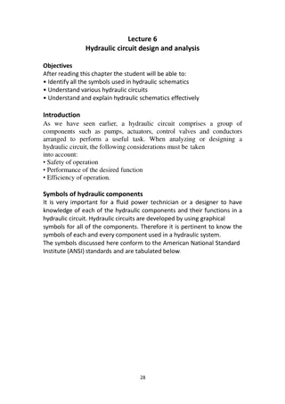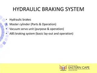
Caterpillar Cat 301.6 Mini Hydraulic Excavator (Prefix 3YW) Service Repair Manual Instant Download
Please open the website below to get the complete manualnn//
Download Presentation

Please find below an Image/Link to download the presentation.
The content on the website is provided AS IS for your information and personal use only. It may not be sold, licensed, or shared on other websites without obtaining consent from the author. Download presentation by click this link. If you encounter any issues during the download, it is possible that the publisher has removed the file from their server.
E N D
Presentation Transcript
Service Repair Manual Models 301.5301.6301.8 M ini Hydraulic Excavator
301.5 301.6 301.8 Mini Hydraulic Excavator 3YW00001-UP (MACHINE) POWERE... 1/11 Shutdown SIS Previous Screen Product: MINI HYD EXCAVATOR Model: 301.5 MINI HYD EXCAVATOR 3YW Configuration: 301.5 301.6 301.8 Mini Hydraulic Excavator 3YW00001-UP (MACHINE) POWERED BY 3003 Engine Disassembly and Assembly 301.5, 301.6 and 301.8 Mini-Hydraulic Excavator Engine Supplement Media Number -RENR2803-01 Publication Date -01/05/2005 Date Updated -11/05/2005 i00914441 Engine and Pumps - Install SMCS - 1017-012; 1024-012 Installation Procedure Table 1 Required Tools Tool Part Number Part Description Qty A 6V-2157 Link Bracket 2 Personal injury can result from hydraulic oil pressure and hot oil. Hydraulic oil pressure can remain in the hydraulic system after the engine has been stopped. Serious injury can be caused if this pressure is not released before any service is done on the hydraulic system. Make sure all of the attachments have been lowered, oil is cool before removing any components or lines. Remove the oil filler cap only when the engine is stopped, and the filler cap is cool enough to touch with your bare hand. At operating temperature, the engine coolant is hot and under pressure. https://127.0.0.1/sisweb/sisweb/techdoc/techdoc_print_page.jsp?returnurl=/sis... 2020/4/19
301.5 301.6 301.8 Mini Hydraulic Excavator 3YW00001-UP (MACHINE) POWERE... 2/11 Steam can cause personal injury. Check the coolant level only after the engine has been stopped and the fill cap is cool enough to touch with your bare hand. Remove the fill cap slowly to relieve pressure. Cooling system conditioner contains alkali. Avoid contact with the skin and eyes to prevent personal injury. Illustration 1 g00489663 1. Apply suitable lifting chains to the lifting points on the engine. Apply enough tension on the chains in order to support the weight of the engine. 2. Lower the engine and pumps into position in the engine compartment. The weight of the engine and pumps is 125 kg (275 lb) . Illustration 2 g00489665 https://127.0.0.1/sisweb/sisweb/techdoc/techdoc_print_page.jsp?returnurl=/sis... 2020/4/19
https://www.ebooklibonline.com Hello dear friend! Thank you very much for reading. Enter the link into your browser. The full manual is available for immediate download. https://www.ebooklibonline.com
301.5 301.6 301.8 Mini Hydraulic Excavator 3YW00001-UP (MACHINE) POWERE... 3/11 3. Install six bolts and washers (44) . The other three bolts are located on the rear of the engine. Illustration 3 g00489661 4. Install two nuts and two washers (43) . Illustration 4 g00489579 5. Install electrical clip (42) . 6. Install the bolt and washer (41) . https://127.0.0.1/sisweb/sisweb/techdoc/techdoc_print_page.jsp?returnurl=/sis... 2020/4/19
301.5 301.6 301.8 Mini Hydraulic Excavator 3YW00001-UP (MACHINE) POWERE... 4/11 Illustration 5 g00489577 7. Install the exhaust manifold and install four nuts (40) . Illustration 6 g00489569 8. Install ground cable (39) . 9. Install clip (38) . 10. Install the bolt and washer (37) . 11. Install nut (36) . https://127.0.0.1/sisweb/sisweb/techdoc/techdoc_print_page.jsp?returnurl=/sis... 2020/4/19
301.5 301.6 301.8 Mini Hydraulic Excavator 3YW00001-UP (MACHINE) POWERE... 5/11 Illustration 7 g00489511 12. Install hose (35) and tighten the hose clamp. 13. Install two hoses (34) . Illustration 8 g00489455 14. Install two electrical clips (33) . 15. Install the two bolts and washers (32) . https://127.0.0.1/sisweb/sisweb/techdoc/techdoc_print_page.jsp?returnurl=/sis... 2020/4/19
301.5 301.6 301.8 Mini Hydraulic Excavator 3YW00001-UP (MACHINE) POWERE... 6/11 Illustration 9 g00489449 16. Install plate assembly (31) . 17. Install the wires. Install two bolts and washers (30) . 18. Install two bolts and washers (29) . Illustration 10 g00489391 19. Install electrical reset (28) and install two bolts. 20. Install battery (27) . 21. Install battery bracket (26) . 22. Install the bolt and washer (25) . 23. Connect the battery cables. Illustration 11 g00489387 24. Install hose (24) . https://127.0.0.1/sisweb/sisweb/techdoc/techdoc_print_page.jsp?returnurl=/sis... 2020/4/19
301.5 301.6 301.8 Mini Hydraulic Excavator 3YW00001-UP (MACHINE) POWERE... 7/11 Illustration 12 g00489386 25. Install hose (23) . 26. Tighten hose clamp (22) . Illustration 13 g00489385 27. Place the engine throttle cable in position and tighten nut (21) . 28. Install pin (20) and install clip (19) . https://127.0.0.1/sisweb/sisweb/techdoc/techdoc_print_page.jsp?returnurl=/sis... 2020/4/19
301.5 301.6 301.8 Mini Hydraulic Excavator 3YW00001-UP (MACHINE) POWERE... 8/11 Illustration 14 g00489383 29. Install wire (18) and install nut (17) . Illustration 15 g00489382 30. Install wire (16) and install bolt (15) . Illustration 16 g00489381 31. Install two hoses (14) and tighten two hose clamps (13) . https://127.0.0.1/sisweb/sisweb/techdoc/techdoc_print_page.jsp?returnurl=/sis... 2020/4/19
301.5 301.6 301.8 Mini Hydraulic Excavator 3YW00001-UP (MACHINE) POWERE... 9/11 Illustration 17 g00489258 Note: The seat is removed for photographic purposes. 32. Install tooling (A) and apply suitable lifting straps. 33. Install wall plate assembly (12) . Illustration 18 g00489256 34. Install two bolts and washers (11) . 35. Install three bolts and washers (10) . https://127.0.0.1/sisweb/sisweb/techdoc/techdoc_print_page.jsp?returnurl=/sis... 2020/4/19
301.5 301.6 301.8 Mini Hydraulic Excavator 3YW00001-UP (MACHINE) POWER... 10/11 Illustration 19 g00489254 36. Install two bolts and washers (9) . 37. Install three bolts and washers (8) . Illustration 20 g00489253 38. Remove fuel tank cap (4) and install side panel (7) . 39. Install the bolt and washer (6) . 40. Install bolt (5) . 41. Install fuel tank cap (4) . https://127.0.0.1/sisweb/sisweb/techdoc/techdoc_print_page.jsp?returnurl=/sis... 2020/4/19
301.5 301.6 301.8 Mini Hydraulic Excavator 3YW00001-UP (MACHINE) POWER... 11/11 Illustration 21 g00465682 42. Install left side corner protector (3) . 43. Tighten two bolts (2) . 44. Install the two bolts and washers (1) . ,,,,, End By: a. Install the cab. Refer to Disassembly and AssemblyRENR2808, "Cab - Install" . b. Install the alternator. Refer to Disassembly and AssemblyRENR2803, "Alternator - Remove and Install" . c. Install the electric starting motor. Refer to Disassembly and AssemblyRENR2803, "Electric Starting Motor - Remove and Install" . d. Install the radiator. Refer to Disassembly and AssemblyRENR2803, "Radiator and Fan - Remove and Install" . e. Install the hood. Refer to Disassembly and AssemblyRENR2803, "Hood - Remove and Install" . Copyright 1993 - 2020 Caterpillar Inc. Sun Apr 19 18:58:12 UTC+0800 2020 All Rights Reserved. Private Network For SIS Licensees. https://127.0.0.1/sisweb/sisweb/techdoc/techdoc_print_page.jsp?returnurl=/sis... 2020/4/19
301.5 301.6 301.8 Mini Hydraulic Excavator 3YW00001-UP (MACHINE) POWERE... 1/3 Shutdown SIS Previous Screen Product: MINI HYD EXCAVATOR Model: 301.5 MINI HYD EXCAVATOR 3YW Configuration: 301.5 301.6 301.8 Mini Hydraulic Excavator 3YW00001-UP (MACHINE) POWERED BY 3003 Engine Disassembly and Assembly 3003, 3013, 3014 and 3024 Engines for Caterpillar Built Machines Media Number -SENR5027-05 Publication Date -01/05/2005 Date Updated -16/05/2005 i01783524 Fuel Filter Base - Remove SMCS - 1262-011 Removal Procedure NOTICE Keep all parts clean from contaminants. Contaminants may cause rapid wear and shortened component life. NOTICE Care must be taken to ensure that fluids are contained during performance of inspection, maintenance, testing, adjusting and repair of the product. Be prepared to collect the fluid with suitable containers before opening any compartment or disassembling any component containing fluids. Refer to Special Publication, NENG2500, "Caterpillar Tools and Shop Products Guide" for tools and supplies suitable to collect and contain fluids on Caterpillar products. Dispose of all fluids according to local regulations and mandates. https://127.0.0.1/sisweb/sisweb/techdoc/techdoc_print_page.jsp?returnurl=/sis... 2020/4/19
301.5 301.6 301.8 Mini Hydraulic Excavator 3YW00001-UP (MACHINE) POWERE... 2/3 Illustration 1 g00767792 Typical example 1. Remove fuel filter (5) from the fuel filter base, as follows: a. Remove the collar and cap (1) from the top of fuel filter base (2). This will help prevent spillage of fuel from the fuel filter. b. Hold fuel filter (5) while locking collar (4) is turned in the counterclockwise direction. c. Pull fuel filter (5) from fuel filter base (2) and remove locking collar (4) . 2. Disconnect fuel line (3) from fuel filter base (2). Plug all openings or cap all openings immediately in order to help prevent contamination. Illustration 2 g00767793 Typical example 3. Remove two bolts (6) that fasten fuel filter base (2) to the mounting bracket. 4. Remove fuel filter base (2) from the mounting bracket. https://127.0.0.1/sisweb/sisweb/techdoc/techdoc_print_page.jsp?returnurl=/sis... 2020/4/19
301.5 301.6 301.8 Mini Hydraulic Excavator 3YW00001-UP (MACHINE) POWERE... 3/3 Note: Some engines may have a hand priming pump on the fuel filter base. Refer to the Disassembly and Assembly, "Fuel Filter Base - Disassemble" topic for information on removing the hand priming pump. Copyright 1993 - 2020 Caterpillar Inc. Sun Apr 19 18:59:31 UTC+0800 2020 All Rights Reserved. Private Network For SIS Licensees. https://127.0.0.1/sisweb/sisweb/techdoc/techdoc_print_page.jsp?returnurl=/sis... 2020/4/19
301.5 301.6 301.8 Mini Hydraulic Excavator 3YW00001-UP (MACHINE) POWERE... 1/3 Shutdown SIS Previous Screen Product: MINI HYD EXCAVATOR Model: 301.5 MINI HYD EXCAVATOR 3YW Configuration: 301.5 301.6 301.8 Mini Hydraulic Excavator 3YW00001-UP (MACHINE) POWERED BY 3003 Engine Disassembly and Assembly 3003, 3013, 3014 and 3024 Engines for Caterpillar Built Machines Media Number -SENR5027-05 Publication Date -01/05/2005 Date Updated -16/05/2005 i01783533 Fuel Filter Base - Disassemble SMCS - 1262-015 Disassembly Procedure Hand Priming Pump (if equipped) https://127.0.0.1/sisweb/sisweb/techdoc/techdoc_print_page.jsp?returnurl=/sis... 2020/4/19
301.5 301.6 301.8 Mini Hydraulic Excavator 3YW00001-UP (MACHINE) POWERE... 2/3 Illustration 1 g00732631 Hand Priming Pump (1) Cap ring (2) Priming button (3) Diaphragm (4) Spring cap (5) Spring (6) Valve plate (7) O-ring seal (8) Fuel filter base 1. Unscrew cap ring (1) from fuel filter base (8). https://127.0.0.1/sisweb/sisweb/techdoc/techdoc_print_page.jsp?returnurl=/sis... 2020/4/19
301.5 301.6 301.8 Mini Hydraulic Excavator 3YW00001-UP (MACHINE) POWERE... 3/3 Personal injury can result from being struck by parts propelled by a released spring force. Make sure to wear all necessary protective equipment. Follow the recommended procedure and use all recommended tooling to release the spring force. 2. Remove priming button (2) and diaphragm (3) from spring cap (4). Inspect the rubber diaphragm (3) for cracks or for wear. If the diaphragm is worn or damaged, use a new part for replacement. 3. Remove spring cap (4) and spring (5) from valve plate (6) . 4. Remove valve plate (6) from fuel filter base (8). Copyright 1993 - 2020 Caterpillar Inc. Sun Apr 19 19:00:28 UTC+0800 2020 All Rights Reserved. Private Network For SIS Licensees. https://127.0.0.1/sisweb/sisweb/techdoc/techdoc_print_page.jsp?returnurl=/sis... 2020/4/19
301.5 301.6 301.8 Mini Hydraulic Excavator 3YW00001-UP (MACHINE) POWERE... 1/3 Shutdown SIS Previous Screen Product: MINI HYD EXCAVATOR Model: 301.5 MINI HYD EXCAVATOR 3YW Configuration: 301.5 301.6 301.8 Mini Hydraulic Excavator 3YW00001-UP (MACHINE) POWERED BY 3003 Engine Disassembly and Assembly 3003, 3013, 3014 and 3024 Engines for Caterpillar Built Machines Media Number -SENR5027-05 Publication Date -01/05/2005 Date Updated -16/05/2005 i01783534 Fuel Filter Base - Assemble SMCS - 1262-016 Assembly Procedure Hand Priming Pump (if equipped) https://127.0.0.1/sisweb/sisweb/techdoc/techdoc_print_page.jsp?returnurl=/sis... 2020/4/19
301.5 301.6 301.8 Mini Hydraulic Excavator 3YW00001-UP (MACHINE) POWERE... 2/3 Illustration 1 g00732631 Hand Priming Pump (1) Cap ring (2) Priming button (3) Diaphragm (4) Spring cap (5) Spring (6) Valve plate (7) O-ring seal (8) Fuel filter base 1. Apply a thin film of clean engine oil to O-ring seal (7) and to valve plate (6) . https://127.0.0.1/sisweb/sisweb/techdoc/techdoc_print_page.jsp?returnurl=/sis... 2020/4/19
301.5 301.6 301.8 Mini Hydraulic Excavator 3YW00001-UP (MACHINE) POWERE... 3/3 2. Insert valve plate (6) into fuel filter base (8). The valve plate must be installed with the O- ring (7) first. Ensure that the rubber valve extends through the center hole of fuel filter base (8). Push valve plate (6) firmly into the correct position. Improper assembly of parts that are spring loaded can cause bodily injury. To prevent possible injury, follow the established assembly procedure and wear protective equipment. 3. Install spring (5) into valve plate (6) and place spring cap (4) on top of the spring. 4. Install rubber diaphragm (3) into priming button (2). Ensure that diaphragm (3) fits firmly into the correct position. Place the assembly over spring cap (4) . 5. Install cap ring (1) over priming button (2). Depress priming button (2) until diaphragm (3) is seated firmly onto fuel filter base (8). Tighten cap ring (1) hand tight while the priming button (2) is depressed. 6. Prime the fuel system. Refer to Testing and Adjusting, "Fuel System - Prime" for more information. Copyright 1993 - 2020 Caterpillar Inc. Sun Apr 19 19:01:24 UTC+0800 2020 All Rights Reserved. Private Network For SIS Licensees. https://127.0.0.1/sisweb/sisweb/techdoc/techdoc_print_page.jsp?returnurl=/sis... 2020/4/19
301.5 301.6 301.8 Mini Hydraulic Excavator 3YW00001-UP (MACHINE) POWERE... 1/2 Shutdown SIS Previous Screen Product: MINI HYD EXCAVATOR Model: 301.5 MINI HYD EXCAVATOR 3YW Configuration: 301.5 301.6 301.8 Mini Hydraulic Excavator 3YW00001-UP (MACHINE) POWERED BY 3003 Engine Disassembly and Assembly 3003, 3013, 3014 and 3024 Engines for Caterpillar Built Machines Media Number -SENR5027-05 Publication Date -01/05/2005 Date Updated -16/05/2005 i01783535 Fuel Filter Base - Install SMCS - 1262-012 Installation Procedure NOTICE Keep all parts clean from contaminants. Contaminants may cause rapid wear and shortened component life. Illustration 1 g00767793 Typical example 1. Put fuel filter base (2) in position on the mounting bracket. https://127.0.0.1/sisweb/sisweb/techdoc/techdoc_print_page.jsp?returnurl=/sis... 2020/4/19
301.5 301.6 301.8 Mini Hydraulic Excavator 3YW00001-UP (MACHINE) POWERE... 2/2 2. Install two bolts (6) that fasten the fuel filter base to the mounting bracket. Illustration 2 g00767792 Typical example 3. Remove the cap or the plug and connect fuel line (3) to fuel filter base (2) . 4. Install fuel filter (5) on fuel filter base (2), as follows: a. Replace the seal on fuel filter base (2) . b. Insert fuel filter (5) in fuel filter base (2) . c. Install collar (4) on the fuel filter and turn the collar in the clockwise direction in order to lock fuel filter (5) on the fuel filter base. The locking collar is hand tightened only. d. Insert cap (1) into the top of fuel filter base (2). Install the collar that holds the cap into position. Note: Some engines may have a hand priming pump on the fuel filter base. Refer to the Disassembly and Assembly Module, "Fuel Filter Base - Assemble" topic for information on installing the hand priming pump. Copyright 1993 - 2020 Caterpillar Inc. Sun Apr 19 19:02:21 UTC+0800 2020 All Rights Reserved. Private Network For SIS Licensees. https://127.0.0.1/sisweb/sisweb/techdoc/techdoc_print_page.jsp?returnurl=/sis... 2020/4/19
301.5 301.6 301.8 Mini Hydraulic Excavator 3YW00001-UP (MACHINE) POWERE... 1/2 Shutdown SIS Previous Screen Product: MINI HYD EXCAVATOR Model: 301.5 MINI HYD EXCAVATOR 3YW Configuration: 301.5 301.6 301.8 Mini Hydraulic Excavator 3YW00001-UP (MACHINE) POWERED BY 3003 Engine Disassembly and Assembly 3003, 3013, 3014 and 3024 Engines for Caterpillar Built Machines Media Number -SENR5027-05 Publication Date -01/05/2005 Date Updated -16/05/2005 i01590349 Fuel Transfer Pump - Remove SMCS - 1256-011 Removal Procedure NOTICE Keep all parts clean from contaminants. Contaminants may cause rapid wear and shortened component life. NOTICE Care must be taken to ensure that fluids are contained during performance of inspection, maintenance, testing, adjusting and repair of the product. Be prepared to collect the fluid with suitable containers before opening any compartment or disassembling any component containing fluids. Refer to Special Publication, NENG2500, "Caterpillar Tools and Shop Products Guide" for tools and supplies suitable to collect and contain fluids on Caterpillar products. Dispose of all fluids according to local regulations and mandates. https://127.0.0.1/sisweb/sisweb/techdoc/techdoc_print_page.jsp?returnurl=/sis... 2020/4/19
Suggest: If the above button click is invalid. Please download this document first, and then click the above link to download the complete manual. Thank you so much for reading
301.5 301.6 301.8 Mini Hydraulic Excavator 3YW00001-UP (MACHINE) POWERE... 2/2 Illustration 1 g00824616 1. Loosen hose clamps and remove the two fuel lines from fuel transfer pump (1) . 2. Remove two bolts (4) that fasten fuel transfer pump (1) to the cylinder block. Note: Before removing the fuel transfer pump (1) from the cylinder block, note the position of the flange (2) of the fuel transfer pump (1) for assembly. 3. Remove fuel transfer pump (1) and O-ring (3). Replace the O-ring when you install the fuel transfer pump. Note: In order to remove the fuel transfer pump from the engine, it may be necessary to rotate the crankshaft until the rocker arm of the fuel transfer pump is not under pressure. Copyright 1993 - 2020 Caterpillar Inc. Sun Apr 19 19:03:18 UTC+0800 2020 All Rights Reserved. Private Network For SIS Licensees. https://127.0.0.1/sisweb/sisweb/techdoc/techdoc_print_page.jsp?returnurl=/sis... 2020/4/19
https://www.ebooklibonline.com Hello dear friend! Thank you very much for reading. Enter the link into your browser. The full manual is available for immediate download. https://www.ebooklibonline.com

