Modified Transmit Spectral Mask for IEEE P802.15 Working Group
This submission presents a modified transmit spectral mask for TG3e by Japan Radio Co., Ltd. The proposed mask aims to improve power efficiency without violating radio regulations. The motivation for the modification is to reduce unwanted aliasing and enhance SNR by employing a steep anti-aliasing slope. The proposed mask shows negligible impact on adjacent channels' SNR. Figures detailing the current and proposed spectral masks for single-channel operation are provided.

Download Presentation

Please find below an Image/Link to download the presentation.
The content on the website is provided AS IS for your information and personal use only. It may not be sold, licensed, or shared on other websites without obtaining consent from the author. Download presentation by click this link. If you encounter any issues during the download, it is possible that the publisher has removed the file from their server.
E N D
Presentation Transcript
<June 2016> doc.: IEEE 802.15-15-0427-00-003e Project: IEEE P802.15 Working Group for Wireless Personal Area Networks (WPANs) Submission Title: [Transmit spectral mask modification ] Date Submitted: [31 May, 2016] Source: [Itaru Maekawa and Jun Kobayashi] Company [Japan Radio Co., Ltd.] Address [Mitaka, Tokyo, Japan] Voice: [+81.422.45.9228], E-Mail: [Maekawa.Itaru@jrc.co.jp, kobayashi.jun@jrc.co.jp] Abstract: [This document presents a modified transmit spectral mask for TG3e.] Purpose: [Transmit spectral mask modification - CID 1068 and 1069.] Notice: This document has been prepared to assist the IEEE P802.15. It is offered as a basis for discussion and is not binding on the contributing individual(s) or organization(s). The material in this document is subject to change in form and content after further study. The contributor(s) reserve(s) the right to add, amend or withdraw material contained herein. Release: The contributor acknowledges and accepts that this contribution becomes the property of IEEE and may be made publicly available by P802.15. Slide 1 Kobayashi (JRC) submission
<Jun. 2016> doc.: IEEE 802.15-15-0427-00-003e Summary A modified spectral mask for TG3e is presented. Power efficiency will be improved by employing the proposed mask. This proposed transmit spectral mask does not violate the radio regulations of any country. Any degradation of SNR at the adjacent channels due to this mask change is negligible, since the maximum allowable leakage power will only increase by less than 0.2dB. Slide 2 Kobayashi (JRC) submission
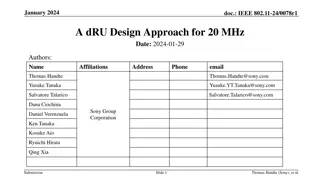
<Jun. 2016> doc.: IEEE 802.15-15-0427-00-003e Motivation for a modified transmit spectral mask In Figure 1, the spectrum of the transmit signal with a two-times oversampling DAC is compared with the current mask. To reduce unwanted aliasing without degrading SNR, the slope of anti-aliasing needs to be steep as shown below. A high-order passive filter can be used to achieve such a purpose; however, insertion loss caused by the on-chip inductor will be large. 10 Wide bandwidth Anti-aliasing filter response Unfiltered DAC output Current Mask 0 Shape slope -10 PSD (dBr) -20 -30 -40 0 0.88 1.76 2.64 3.52 4.4 5.28 Frequency (GHz) Figure 1 Unfiltered two-times oversampled DAC output Slide 3 Kobayashi (JRC) submission
<Jun. 2016> doc.: IEEE 802.15-15-0427-00-003e Current transmit spectral mask for a single channel Figure 2 Current transmit spectral mask for single-channel operation Slide 4 Kobayashi (JRC) submission
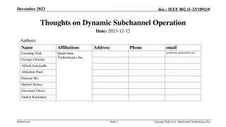
<Jun. 2016> doc.: IEEE 802.15-15-0427-00-003e Proposed transmit spectral mask for a single channel operation PSD (dBr) Proposed Mask Current Mask -17dBr -22dBr -30dBr - 4 0 -3.3 3.3 0.94 1.2 -3.06 -1.2 -0.94 3.06 -4 -2 0 2 4 (f-fc) GHz Figure 3 Proposed spectral mask Slide 5 Kobayashi (JRC) submission
<Jun. 2016> doc.: IEEE 802.15-15-0427-00-003e Current transmit spectral mask for channel-bonded case Figure 4 Current transmit spectral mask for channel-bonded case Table 1 Current spectral mask parameters for channel-bonded case Channel bonding f1 (GHz) f2 (GHz) f3 (GHz) f4 (GHz) Two-bonded channel transmission 2.100 2.160 3.000 4.000 Three-bonded channel transmission 3.150 3.240 4.500 6.000 Four-bonded channel transmission 4.200 4.320 6.000 8.000 Slide 6 Kobayashi (JRC) submission
<Jun. 2016> doc.: IEEE 802.15-15-0427-00-003e Proposed transmit spectral mask for channel-bonded operation PSD (dBr) Proposed Mask Current Mask -17dBr -30dBr - 4 0 -f2 -f1 -4 -f3 f1 f2 f3 (f-fc) GHz -8 -6 -2 0 2 4 6 8 Figure 5 Proposed spectral mask for channel-bonded operation Table.2 Proposed spectral mask parameters for channel-bonded operation Channel bonded case f1 (GHz) f2 (GHz) f3 (GHz) Two-channel bonded transmission 1.880 2.400 4.000 Three-channel bonded transmission 2.820 3.600 6.000 Four-channel bonded transmission 3.760 4.800 8.000 Slide 7 Kobayashi (JRC) submission
<Jun. 2016> doc.: IEEE 802.15-15-0427-00-003e Filter power consumption The integrated anti-aliasing filter for the transmitter is commonly realized as either an active or passive filter. High-order passive filters cause a large insertion loss as mentioned before. However, power consumption of an active anti-aliasing filter is too large for a ultra-short range (up to 10 cm) wireless system, whose output power is typically -5dBm (0.3 mW) [1]. The total power efficiency of the system is hard to be optimize. Table 3 Filter power consumption Filter Architecture Gm-C Passive Power Consumption/channel (mW) 70 to 150 0 Ref [2], [3] Slide 8 Kobayashi (JRC) submission
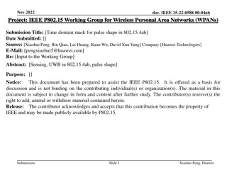
<Jun. 2016> doc.: IEEE 802.15-15-0427-00-003e Simulated EVM and filtered DAC output for a single channel operation Figure 6 shows the Tx EVM as a function of filter order for 4 different cutoff frequencies. This simulation does not consider the contribution of aliasing effect. Figure 7 shows the filtered DAC output for 4 different cutoff frequencies. 0 10 1.2GHz 1.4GHz LPF: 3rd order Butterworth Cutoff Freq=1.2GHz 1.6GHz 1.8GHz Cutoff Freq=1.4GHz -10 0 Cutoff Freq=1.6GHz EVM degraded by amplitude distortion EVM degraded by group delay Cutoff Freq=1.8GHz -20 -10 EVM (dB) Current Mask PSD (dBr) -30 -20 -30 -40 -40 -50 0 0.88 1.76 2.64 3.52 4.4 5.28 1 2 3 4 5 Frequency (GHz) Butterworth Low Pass Filter Order Figure 6 Simulated EVM vs filter order and cutoff frequency The 3rd order LPF (cutoff freq.=1.8GHz) achieves a small SNR degradation and low insertion loss. but, the transmit spectrum exceeds the current spectral mask for a single channel. Figure 7 Filtered DAC output and filter cutoff frequency Slide 9 Kobayashi (JRC) submission
<Jun. 2016> doc.: IEEE 802.15-15-0427-00-003e Proposed transmit spectral mask for a single channel and filtered DAC output 10 LPF 3rd order butterworth Cutoff Freq=1.2GHz Cutoff Freq=1.4GHz 0 Cutoff Freq=1.6GHz Cutoff Freq=1.8GHz Margin -10 Proposed Mask2 PSD (dBr) -20 -30 -40 0 0.88 1.76 2.64 3.52 4.4 5.28 Frequency (GHz) Figure 8 Proposed transmit spectral mask and filtered DAC output Slide 10 Kobayashi (JRC) submission
<Jun. 2016> doc.: IEEE 802.15-15-0427-00-003e Proposed transmit spectral mask for bonded channel and filtered DAC output The slope between f1 offset and f2 offset is the same as that of the current mask for single channel operation. 10 Filtered DAC output 2 channel bonding Current Mask Proposed Mask 0 Slope is same as for single channel operation -10 PSD (dBr) -20 -30 -40 f0 f1 f2 f3 0 2 4 6 8 Frequency (GHz) Fig.9 Proposed spectral mask for 2-channel bonding and filtered DAC output Slide 11 Kobayashi (JRC) submission
<Jun. 2016> doc.: IEEE 802.15-15-0427-00-003e Summary of 60 GHz radio regulations Table 4 Radio regulations Antenna power Or Conducted Power Occupied bandwidth (GHz) Allowable value of unwanted emission intensity Frequency (GHz) Country Antenna gain EIRP Ref Not Less than 55.62GHz -30dBm/MHz max Over 55.62GHz less than 57GHz -26dBm/MHz max Over 66GHz less than 67.5GHz -26dBm/MHz max Over 67.5GHz -30dBm/MHz max 47 dBi max. 10dBm max specified Japan 9 [4] 57 66 Over 10dBm less than 24dBm 10dBi or over 40 dBm max Not EIRP = 82 dBm -2*(51 - Antenna gain) less than 51 dBi Specified Not Outdoor United States 40GHz-200GHz 90pW/cm^2 @3m (EIRP =-10dBm) *2 specified Not 57-64 51 dBi or over EIRP = 82 dBm [5] Specified Not Indoor less than 27 dBi 27 dBm max *1 40 dBm specified Not Not Not 1GHz-130GHz -30 dBm/MHz Europe 57-66 40 dBm max [6] specified specified specified Not 40 GHz or Over -20dBm /MHz China 59-64 34dBi max 10dBm max 44 dBm max [7] specified Slide 12 Kobayashi (JRC) submission
<Jun. 2016> doc.: IEEE 802.15-15-0427-00-003e The proposed transmit spectral mask for a single channel and unwanted emission intensity Transmit power of ultra short range system is typically -5dBm. The proposed transmit spectral mask does not infringe on any country s regulatory requirements. 5 Japan China Proposed Mask ETSI US FCC 15.209 -5 -15 -25 PSD (dBm/MHz) -35 -45 -55 -65 -75 50 52.5 55 57.5 60 62.5 65 67.5 70 72.5 Frequency (GHz) Figure 10 Proposed mask and allowed unwanted emission intensity Slide 13 Kobayashi (JRC) submission
<Jun. 2016> doc.: IEEE 802.15-15-0427-00-003e The proposed transmit spectral mask for channel bonding and un-wanted emission intensity Transmit power of ultra short range system is typically -5dBm. The proposed transmit spectral mask does not infringe on any country s regulatory requirements. 5 Japan China Proposed Mask 2channel bonding Proposed Mask 4channel bonding ETSI US FCC 15.209 Proposed Mask 3channel bonding -5 -15 -25 PSD (dBm/MHz) -35 -45 -55 -65 -75 52.5 55 57.5 60 62.5 65 67.5 70 Frequency (GHz) Figure 11 Proposed mask for channel bonding and allowed unwanted emission intensity Slide 14 Kobayashi (JRC) submission
<Jun. 2016> doc.: IEEE 802.15-15-0427-00-003e Adjacent channel leakage power of proposed spectral mask for a single channel The difference in leakage power to an adjacent channel (D/U ratio=0 dB) for the case of the current mask and proposed mask is less than 0.2dB. The effect on the SNR of adjacent channels is negligible. 10 Proposed Mask Reference channel Current Mask Lower channel Upper channnel 0 Upper Adjacent Channel Lower Adjacent Channel Reference Channel Leakage -10 PSD (dBr) -20 -30 -40 -6 -4 -2 0 2 4 6 Frequency (GHz) Figure 12 Adjacent channels and leakage power Slide 15 Kobayashi (JRC) submission
<Jun. 2016> doc.: IEEE 802.15-15-0427-00-003e References [1] 15-15-0109-07-003e, TG3e Technical Guidance Document [2] S.Pavan and Y.Tsividis, High Frequency Continuous Time Filters in Digital CMOS Processes, Kluwer, Boston, 2000. [3] A.Siligarls, et al., A 65-nm CMOS Fully Integrated Transceiver Module for 60-GHz Wireless HD Applications, IEEE ISSCC, pp.162-163, Feb.2011. [4] Japan Regulations for enforcement of the radio law 6-4-2 Specified Low Power Radio Station 59-66 GHz Band. [5] Part 15 Rules for Unlicensed Operation in the 57-64 GHz Band DA/FCC: FCC-13-112. [6] ETSI EN 302 567 V1.2.1. [7] [2005]423 . Slide 16 Kobayashi (JRC) submission
<Jun. 2016> doc.: IEEE 802.15-15-0427-00-003e END Slide 17 Kobayashi (JRC) submission