IEEE 802.11-23/1288r0 Bandwidth Utilization Proposal
This proposal aims to improve bandwidth utilization in IEEE 802.11 networks by allowing devices to transmit on idle channels within the operating bandwidth. It addresses the inefficiencies caused by the current limitation where devices do not transmit on idle portions if the primary channel is busy. The proposal considers transmitter and receiver capabilities, operating modes, protection mechanisms, and scenarios of interest to enhance overall network performance and efficiency.
Download Presentation

Please find below an Image/Link to download the presentation.
The content on the website is provided AS IS for your information and personal use only. It may not be sold, licensed, or shared on other websites without obtaining consent from the author. Download presentation by click this link. If you encounter any issues during the download, it is possible that the publisher has removed the file from their server.
E N D
Presentation Transcript
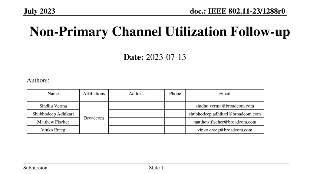
doc.: IEEE 802.11-23/1288r0 July 2023 Non-Primary Channel Utilization Follow-up Date: 2023-07-13 Authors: Name Affiliations Address Phone Email Sindhu Verma sindhu.verma@broadcom.com Shubhodeep Adhikari shubhodeep.adhikari@broadcom.com Broadcom Matthew Fischer matthew.fischer@broadcom.com Vinko Erceg vinko.erceg@broadcom.com Submission Slide 1
doc.: IEEE 802.11-23/1288r0 Abstract This is a proposal to allow the utilization of some portion of the operating bandwidth when another portion of the operating bandwidth has been detected as BUSY Submission Slide 2
doc.: IEEE 802.11-23/1288r0 Overview Problem Statement High-level Solution Relevant Transmitter capabilities Relevant Receiver capabilities Proposed Operating Modes Protection Mechanisms Scenarios of Interest Simulation results Conclusion Submission Slide 3
doc.: IEEE 802.11-23/1288r0 Problem Statement If the primary 20 MHz channel is busy, an 802.11 STA currently does not transmit on any of the portion of the operating bandwidth, even when those portions are idle Such inefficient bandwidth utilization in 802.11 causes more loss with increasing operating bandwidth. For example, in 802.11be, a busy 20MHz primary channel prevents a STA from accessing an idle 300 MHz of remaining bandwidth. Competing unlicensed technologies operating in the same bands, such as LAA and NR- U, do not have such limitations. They neither have any dependence on any primary 20MHz channel for system information like beacons, nor any need for backward compatibility with legacy devices that operate only on the primary 20MHz channel. However, both these requirements are true for 802.11, which also means that utilization of non-primary channels in 802.11 needs careful design. A channel in this presentation denotes a 20MHz bandwidth unit as defined by regulations and 802.11 and other unlicensed standards. Submission Slide 4
doc.: IEEE 802.11-23/1288r0 High-level Solution The problem of inefficient bandwidth usage can be alleviated by allowing a STA to transmit on a subset of channels that are a part of its operating bandwidth if they are idle and provided other qualifying conditions are met The qualifying conditions need to consider the inherent dependence of 802.11 on a primary 20MHz channel and specifically, the following: Devices of 802.11be and prior standards can transmit only when the primary 20MHz channel is available. Beacons and similar control messages are transmitted only on the primary 20MHz channel Transmitting on any subset of channels of a link renders the transmitting device blind on the channels that are left out from the perspective of CCA. Anytime that a transmitting device is blind on a set of channels for the purpose of CCA, it needs to perform conservative access measures on returning to it so as not to penalize the already transmitting devices. Multiple kinds of transmitter/receiver capabilities (detailed next) Submission Slide 5
doc.: IEEE 802.11-23/1288r0 Relevant Transmitter capabilities Capability type 1: A device can perform full CCA (i.e. ED + virtual CCA) in parallel on multiple channels in its operating bandwidth, including the primary 20MHz. If the primary is BUSY, CCA continues on other channels. During an ongoing preamble decode on one of these channels, preamble decode on other channels is not possible. Capability type 2: A device can perform full CCA on only one channel at a time. So, it can perform full CCA on other channels after it determines the primary is busy but the packet is not relevant to this STA and/or BSS. CCA on non-primary channels is performed only during the occupancy of the primary channel which is determined by examining the duration of the PPDUs and/or TXOP occupying the primary channel Such sequential CCA can delay gaining access on the idle non-primary channels Submission Slide 6
doc.: IEEE 802.11-23/1288r0 Relevant Receiver capabilities Capability Type 1: A receiving device supports listening for preamble in parallel on multiple channels in its operating bandwidth, including the primary channel. However, preamble decode can occur only one channel at a time. This means that a transmitter can choose any of those non-primary channels to transmit to the receiver but with restrictions. Capability Type 2: A receiving device supports listening for preamble on only one channel at a time. So, it can perform preamble detection on other channels after it determines the primary channel is busy. Submission Slide 7
doc.: IEEE 802.11-23/1288r0 Proposed Operating Modes: Option 1 (1) This type of operation is possible if the Receiver has capability Type 1 (i.e. preamble listening on multiple channels in parallel) and the Transmitter has capability Type 1 or 2 (i.e. parallel CCA on multiple channels or sequential CCA on one channel at a time). The Transmitter and Receiver agree on a set of anchor channels The number of anchor channels is less than or equal to the number of channels the receiver supports parallel preamble detect on. But it can be more than the number of channels the transmitter supports parallel CCA on. The anchor channels can be equally spaced in the operating bandwidth of the transmitter/receiver and the first anchor channel is the primary 20MHz channel Any transmissions always include at least one of the anchor channels. Other channels contiguous to the anchor channels can be also included using PIFS CCA. Submission Slide 8
doc.: IEEE 802.11-23/1288r0 Proposed Operating Modes: Option 1 (2) In case the number of channels the Transmitter supports parallel CCA on, is smaller than the number of anchor channels, the transmitter can partition the anchor channels into smaller sets with the same number of channels as it supports parallel CCA on and where it starts fresh CCA processes and medium synchronization processes while moving from one set to the other. Option 1a: Non-primary channels are used if primary 20MHz channel is occupied by an OBSS and only for that duration. This is to be used in the presence of legacy devices where MU-EDCA cannot be used to prevent untriggered UL transmissions Option 1b: Non-primary channels are used if primary 20MHz channel is occupied by an OBSS or any technology and for a duration not restricted by the occupancy of primary 20MHz This can be used for UHR and legacy 802.11 versions where MU-EDCA can be used to prevent untriggered UL transmissions Submission Slide 9
doc.: IEEE 802.11-23/1288r0 Proposed Operating Modes: Option 1 (2) The perspective of the transmitter alone matters. Since the receiver is capable of listening for preamble in parallel on the other anchor channels, it does not matter if it sees the OBSS on the primary 20MHz or not. Since the number of anchor channels is less than or equal to the number of channels the receiver supports parallel preamble detect on, and the anchor channels would be negotiated, the receiver would be capable of preamble detect on any of those channels irrespective of the primary 20MHz being busy. Submission Slide 10
doc.: IEEE 802.11-23/1288r0 Proposed Operating Modes: Option 2 (1) This type of operation is relevant if the receiver has capability Type 2 and the Transmitter has capability Type 1 or 2 i.e. if the receiver supports preamble listening on only one channel at a time. In that case, the receiver which supports preamble listening on one channel at a time, switches to the alternative channel after determining the relevance and duration of the OBSS occupancy of the primary channel. Transmitter and receiver agree on an order of trying different channels for data exchange without there being any anchor channels: The order for example, is ch_1, ch_2, etc. Transmitter performs CCA on the channel in the agreed sequence. This first channel is the primary 20MHz channel. If CCA completes (i.e. the device wins channel access) on the current channel ch_x, it transmits on ch_x. Channels contiguous with ch_x may be included using PIFS CCA Submission Slide 11
doc.: IEEE 802.11-23/1288r0 Proposed Operating Modes: Option 2 (2) If the current channel ch_x is not available and the primary 20MHz channel is occupied by OBSS, the transmitter attempts to transmit on the next channel in the sequence but only for the duration for which the primary 20MHz channel is busy. This continues till all channels are seen to be unavailable. The control returns to the primary 20MHz channel once the duration determined by CCA (e.g. NAV or PPDU length) on the primary 20MHz channel expires. Upon returning to the primary 20MHz channel, Medium Synchronization process on primary need not be used if the return is before the expiry of the decoded OBSS duration Submission Slide 12
doc.: IEEE 802.11-23/1288r0 Proposed Operating Modes: Option 2 (3) This option requires a common understanding between transmitter and receiver of the primary 20MHz channel being occupied by OBSS and of any other channels being not available. Below are two ways to achieve it: Implicit: transmitter and receiver hope to see the same OBSS on the primary 20MHz channel and then move to the next set of channels. There can be a threshold set on the signal strength from the OBSS to increase the probability that both transmitter and receiver see the OBSS. Similar process for determining whether other channels are busy/idle. Explicit: If there is a control link, the transmitter can indicate on it that it has detected OBSS/or other busy activity and is moving on to the next set of channels Submission Slide 13
doc.: IEEE 802.11-23/1288r0 Protection Mechanisms (MU-) RTS to initiate non-primary usage: This ensures actual data is not lost when the receiver is not available on a non-primary channel to receive transmission due to its being engaged in decoding a preamble on another channel. UHR-specific headers: If UHR-specific headers are used to initiate transmissions using this feature, the receiver can more easily and quickly conclude if the transmission is meant for it or whether it should switch back to listening for preambles on the channels it is performing listening on Medium Sync recovery: This needs to be performed on a channel whenever the transmitter loses medium status of any channel Reception of beacons at the non-AP: The receiver should be able to not miss beacons from its AP on the primary channel when trying to detect/decode preambles on non-primary channels MU-EDCA: When the AP moves to transmit on a non-primary channel, non-APs that may be unaware of such a move can be protected by using MU-EDCA so that they do not transmit to the AP on the primary channel or any non-primary channel at that same time Submission Slide 14
doc.: IEEE 802.11-23/1288r0 Scenarios of interest for non-primary channel utilization AP operating bandwidth being larger than the operating bandwidths of one or more OBSSs OBSS DL/UL transmissions being intermittently narrow band due to coverage-limited or power-limited clients or clients which support narrower bandwidth or simply for limited data rate requirements OBSS DL/UL transmissions being narrow band due to their sensing of energy from other technologies. Presence of other technologies (Option 1b i.e. non-primary usage not limited by the duration of occupancy of the primary 20MHz) Multi-AP OFDMA coordination: one AP uses a part of a wider bandwidth overlapping with the primary 20MHz and another uses the complement. OBSSs are of narrower bandwidths and with non-overlapping primary channels and different loads Submission Slide 15
doc.: IEEE 802.11-23/1288r0 Simulation Results: Configuration The following modes are compared: NPCU AP associated with an NPCU client Single-link AP associated with a single-link client 1 link, Bandwidth: 320MHz Fixed MCS =7 , NSS = 2 Traffic: Full-buffer and Finite Rate (64Kbps traffic stream consisting of 160-byte packets) CCA model: AP is able to do parallel CCA on each 20MHz channel. Once CCA succeeds on any 1 channel, the AP performs PIFS CCA on the remaining contiguous 20MHz channels. OBSS model: 1, 2 or 4 OBSS/link. OBSS BW uniformly randomly selected between 20, 40, 80, 160 or 320MHz with aligned primary channels Single-link AP with single-link client (so OBSSs are not constrained by any ML functionality) DL-only traffic Poisson arrival of bursts. Burst size = 200 packets Cumulative data rate = 0%, 25%, 50%, 75%, 100% of the per-link PHY data rate Submission Slide 16
doc.: IEEE 802.11-23/1288r0 Simulation Results: Full buffer throughput (max OBSS bandwidth = 160MHz) The graphs above show the evolution of full buffer throughputs of an NPCU AP associated with a single NPCU client compared to that of an SL AP associated with a SL client The throughputs are evaluated for varying OBSS loads and in the presence of 1/2/4 OBSSs per link each with a random bandwidth of 20/40/80/160MHz It can be seen that the NPCU AP-client system provides up to 250% gain in full buffer throughput relative to SL It can also be seen that for any given number of OBSS/link, in presence of increasing congestion, NPCU throughput declines much slower than legacy. Submission Slide 17
doc.: IEEE 802.11-23/1288r0 Simulation Results: Full buffer throughput (max OBSS bandwidth = 160MHz) The ballpark trends for the gains can be explained as follows: When an OBSS occupies the primary 20MHz, the NPCU transmitter is able to transmit with bandwidth (320MHz - OBSS bandwidth). Consider that OBSS channel occupancy i.e. the ratio of occupancy of the medium by the OBSS is OBSS_CO OBSS_CO is related to OBSS load in the following manner: OBSS_CO = min{OBSS_load/100, num_OBSS/(num_OBSS+1)} In this configuration, the average OBSS bandwidth is (20+40+80+160)/4 = 75MHz. So, when the OBSS occupies the medium, the NPCU AP on an average occupies the remaining bandwidth of 320- 75=255MHz. At this time, its effective data rate is (255/320)*PHY_rate ~= 0.8*PHY_rate, where PHY_rate is the PHY throughput corresponding to a 320MHz transmission with the fixed MCS/NSS. So, the additional throughput gain due to NPCU is upper bounded by (OBSS_CO)*0.8*(PHY_rate). The baseline throughput is (1-OBSS_CO)*PHY_rate This means the gain percentage in this case will be 80*(OBBS_CO)/(1-OBSS_CO) The actual throughput gain compared to the above calculation would be reduced by the additional CCA durations on the non-primary channel(s) and other implementation specific delays. Note: The effective OBSS bandwidth increases depending on the coarseness of CCA and transmission. For example, if the AP can perform CCA only on 4 channels that are 80MHz apart, the minimum OBSS BW in consideration would be 80MHz Submission Slide 18
doc.: IEEE 802.11-23/1288r0 Simulation Results: Full buffer throughput (max OBSS bandwidth = 320MHz) The graphs above show the evolution of full buffer throughputs of an NPCU AP associated with a single NPCU client compared to that of an SL AP associated with a SL client The throughputs are evaluated for varying OBSS loads and in the presence of 1/2/4 OBSSs per link each with a random bandwidth of 20/40/80/160/320 MHz. It can be seen that the NPCU AP-client system provides up to 200% gain in full buffer throughput relative to SL It can also be seen that for any given number of OBSS/link, in presence of increasing congestion, NPCU throughput declines much slower than legacy. Submission Slide 19
doc.: IEEE 802.11-23/1288r0 Simulation Results: Latency (max OBSS bandwidth = 160MHz) The graphs above show the evolution of 50%ile and 99%ile latencies of an NPCU AP associated with a single NPCU client compared to that of an SL AP associated with an SL client for varying OBSS loads and in the presence of 1/2/4 OBSSs per link. The OBSS bandwidth varies randomly between 20/40/80/160 MHz It can be seen that the NPCU AP-client system provides significant reduction in latency relative to SL for any OBSS number and load combination As expected, the latency gain ratio is much higher than the full buffer throughput gain ratio Submission Slide 20
doc.: IEEE 802.11-23/1288r0 Simulation Results: Latency (max OBSS bandwidth = 320MHz) The graphs above show the evolution of 50%ile and 99%ile latencies of an NPCU AP associated with a single NPCU client compared to that of an SL AP associated with an SL client for varying OBSS loads and in the presence of 1/2/4 OBSSs per link. The OBSS bandwidth varies randomly between 20/40/80/160/320 MHz It can be seen that the NPCU AP-client system provides significant reduction in latency relative to SL for any OBSS number and load combination Submission Slide 21
doc.: IEEE 802.11-23/1288r0 Considerations for non-ideal scenarios (1) The simulations in the previous slides consider OBSSs with primary channels aligned with that of the NPCU BSS and all devices above ED relative to each other. While that may be a common observation in the field, NPCU should also be evaluated where such assumptions do not hold true. For that reason, we propose to agree on the following aspects to evaluate NPCU in non-ideal scenarios. This would allow contributors who are interested in NPCU to use a harmonized set of simulation configurations to evaluate NPCU. Orientation of primary 20MHz channels of the NPCU BSS and OBSS How many OBSSs can have unaligned primary channels? Typically, APs that hear each other either align the primary channels or operate in non-overlapping operating bandwidths (The latter effect results indirectly even from operating in overlapping bandwidths but with different primary 20MHz channels) What is the baseline performance in that case? Reliance on the NAV of the primary 20MHz channel How often can CF-end end it prematurely leading to loss of medium sync on primary channel while the NPCU device thinks otherwise Such anomalies were not considered for 11be Medium Sync Recovery Type 1 vs Type 2 operations: In addition to the backoff countdown time, should there be any sensing time or wait time before a non- primary channel can be accessed by Type 2. Why is this needed, especially if NPCU transmissions on non- primary channels follow medium sync procedures and start new backoff process upon moving to it. Submission Slide 22
doc.: IEEE 802.11-23/1288r0 Considerations for non-ideal scenarios (2) Hearing range of devices above ED or between ED and PD How many devices above ED threshold and how many between ED and PD Effective ED threshold of a non-primary 20MHz channel is -72dBm or -75dBm. Given this, all devices heard above -72dBm/20 MHz on the non-primary channels should have perfect medium sync status on them Assumptions regarding above ED devices: Perfect Medium Sync status though no NAV information guaranteed Medium Sync Recovery procedures have no impact Assumptions regarding between ED and PD devices: Medium Sync Recovery procedures have impact RTS-CTS procedure to resolve Medium Sync Loss can be flawed depending on whether both the transmitter and the receiver were blind before it Presence of other NPCU BSSs If we assume that NPCU transmissions would have UHR headers to help identify them, they would be distinguishable from transmissions of legacy BSSs with unaligned primary 20MHz. Specific network topology Do we assume a certain topology with rooms, walls and randomized device placements? Submission Slide 23
doc.: IEEE 802.11-23/1288r0 Conclusion This presentation discussed the need to eliminate a long standing limitation of 802.11 viz. its dependence on the availability of a single 20MHz primary channel for any transmission or reception to take place. Other technologies which have multi-channel (wideband) operation in the unlicensed spectrum, do not share this limitation We have proposed methods to realize utilization of non-primary channels even if the primary 20MHz is unavailable. The methods are compatible with a transmitter/receiver and also coexistence with legacy devices. We have also discussed the scenarios where this feature would be beneficial and presented simulation results showcasing the gains for the most prominent of those scenarios We also proposed to harmonize the simulation configurations to further analyze this feature especially in non-ideal scenarios wide range of capabilities for the Submission Slide 24
