Understanding Primary Clarifiers and Surface Area Calculations

Learn about primary clarifiers used to remove particles in water treatment processes with different types and calculations. Dive into surface area calculations for rectangles, including converting inches to feet for accurate measurements. Practice solving surface area problems for practical application.
- Primary Clarifiers
- Surface Area Calculations
- Water Treatment
- Rectangular Clarifiers
- Clarifier Loading

Download Presentation

Please find below an Image/Link to download the presentation.
The content on the website is provided AS IS for your information and personal use only. It may not be sold, licensed, or shared on other websites without obtaining consent from the author. Download presentation by click this link. If you encounter any issues during the download, it is possible that the publisher has removed the file from their server.
E N D
Presentation Transcript
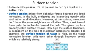
Primary clarifier are usually designed to remove particles with settling rate of 0.3 0.7 mm/sec. Two types of primary clarifiers 1. rectangular 2. circular.
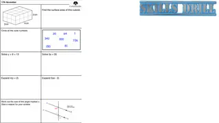
Clarifier Loading Calculations = Tank Volume, MG X 24 Flow into Tank, MGD Detention Time (DT) Flow, gallons/day Surface Area, ft2 = Surface Overflow Rate (SOR) Weir Overflow Rate (WOR) = Flow, gallons/day Length of Weir, ft Solids, lbs/day Surface Area, ft2 Solids Loading =
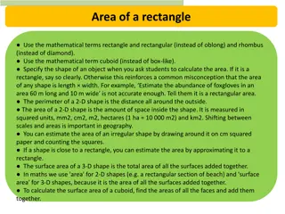
Surface Area Calculations Rectangles Surface Area, ft2 = Length, ft X Width, ft Example 1: If a tank is 10 ft long and 5 ft wide, what is the surface area? SA, ft2 = 10 ft X 5 ft = 50 ft2
Surface Area Calculations Rectangles Surface Area, ft2 = Length, ft X Width, ft Example 2: If a tank is 10 ft 6 inches long and 5 ft 9 inches wide, what is the surface area in sq. ft.? NOT SA, ft2 = 10.6 ft X 5.9 ft
Converting Inches to Feet 6 inches = 6 inches = 0.5 ft 12 in/ft So: 10 ft 6 inches = 10.5 ft 9 inches = 9 inches = 0.75 ft 12 in/ft So: 5 ft 9 inches = 5.75 ft
Surface Area Calculations Rectangles Surface Area, ft2 = Length, ft X Width, ft Example 2: If a tank is 10 ft 6 inches long and 5 ft 9 inches wide, what is the surface area in sq. ft.? SA, ft2 = 10.5 ft X 5.75 ft = 60.4 ft2
Surface Area Calculations Rectangles Surface Area, ft2 = Length, ft X Width, ft Work Calculations on Separate Paper Answers Given on Next Slides Practice 1: If a clarifier is 25 ft long and 9 ft wide, what is the surface area in sq. ft.? Practice 2: If a clarifier is 22 ft 3 inches long and 7 ft 7 inches wide, what is the surface area in sq. ft.?
Surface Area Calculations Rectangles Surface Area, ft2 = Length, ft X Width, ft Practice 1: If a clarifier is 25 ft long and 9 ft wide, what is the surface area in sq. ft.? SA, ft2 = 25 ft X 9 ft = 225 ft2
Surface Area Calculations Rectangles Surface Area, ft2 = Length, ft X Width, ft Practice 2: If a clarifier is 22 ft 3 inches long and 7 ft 7 inches wide, what is the surface area in sq. ft.?
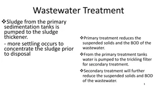
1.0PRIMARY SEDIMENTATION TANKS Primary treatment traditionally implied a sedimentation process to separate the readily settleable and floatable solids from the wastewater. The primary sedimentation tank is where the flow velocity of the wastewater is reduced by plain sedimentation. The process commonly remove particles with a settling rate of 0.3 to 0.6mm/s. The overflow rate of the primary sedimentation tanks ranges from 24.5 to 49m3/m2d (1.02m/h to 2.04m/h) The detention time is the tank is usually 1-3h (typically 2 hours)
Primary tank should removes: * 90 95% of settleable solids * 50 60% of total suspended solids * 25 35% of BOD5 Laboratory analyses of settling-column tests are commonly used to generate design information. The depth should not be less than 3.0m.
If waste activated sludge is returned to the primary clarifier, the design surface settling rate shall not exceed 41m3/(m2d). Weir loading rate should not exceed 250m3 per day linear meter (10m3/h/m)
1.1 Rectangular Basin Design Basin dimensions are to be designed on the basic of surface overflow rate to determine the required basin surface area. An overflow rate of 36m3/(m2d) at average design flow is generally acceptable. The basin length to with ratio of 3:1 is acceptable. Weir loading rates range from 250 to 273m3/(d.m) 1.2 Circular Basin Design Inlet in circular or square basins are typically at the center and the flow is directed upward through a baffle that channels the wastewater (influent) toward the periphery of the tank. Inlet baffles are 10-20 percent of basin diameter and extend 0.9 1.8m below the wastewater surface. A typical depth of sidwall of a circular tank is 3m. The floor slope of the tank is typically 300mm horizontal to 25mm vertical.
Circular tanks shall be no more than 50 m in diameter and the side water depth shall be at a minimum of 3.0 m. Note: If weir loading exceeds 100 m3/day/m at average flow, a multiple v-notch weir must be used. Refer also to Clause 6.3.6 of MS 1228. 5.8 Design of Biological Treatment Stage 5.8.1 Introduction Biological treatment is the heart of the treatment process. It is where the sewage is exposed to living organisms that remove dissolved and non-settleable organic material remaining in the sewage. For reasons of long term whole life economics, ease of operation and maintenance, consistent effluent standards and standardisation, the following types of biological treatment processes are recommended for use in Malaysia. Conventional activated sludge system for PE > 20,000 Extended aeration activated sludge system for all PE
At least two DO meters shall be provided in each tank. The placement of these meters shall allow for easy removal, servicing and calibration. If mechanical aerators are used, a vented enclosure over the aerator shall be provided to minimise noise and aerosol. Aeration pipework shall typically be ductile iron or steel pipe with suitable protection. Galvanised steel or stainless steel shall be used for headers and drop pipes within the aeration tank. PVC pipes shall be restricted to the diffuser laterals and off takes. Tanks, preferably shall not be wider than 30 m for maintenance purposes, which is normally limited by the crane reach. Inlet gates shall be provided at the inlet section of the aeration tanks to isolate each tank. A sump for the drainage of each tank shall be provided. Table 5.9 contains important design parameters.