Rotary Transforming Power Across Rotary Interfaces
Rotary transformers are essential for transferring signals and power across rotary interfaces, replacing slip rings with more reliability. Used in scientific instruments, antennas, and spacecraft configurations like spin-stabilized crafts. The Galileo spacecraft successfully utilized rotary transformers, achieving high data rates and prolonged operational life without glitches. Basic rotary transformers come in axial and flat types, enabling electromagnetic power transfer without wearing contacts, noise, or contamination issues.
Download Presentation

Please find below an Image/Link to download the presentation.
The content on the website is provided AS IS for your information and personal use only. It may not be sold, licensed, or shared on other websites without obtaining consent from the author. Download presentation by click this link. If you encounter any issues during the download, it is possible that the publisher has removed the file from their server.
E N D
Presentation Transcript
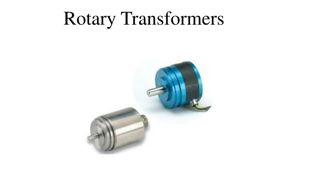
Rotary Transformer Introduction: There are many requirements to transfer signals and power across rotary interfaces. Most things that use slip rings or brushes can be replaced with a rotary transformer. Scientific instruments, antennas and solar arrays are elements needing rotary power transfer for certain Space Craft (S/C) configurations, such as a spin, stabilized (S/C). Delivery of signals and power has mainly been done by slip rings. There are problems in using slip rings for long life and high reliability: due to contact wear, noise, and contamination. Contact wear will lead to a conductive path to ground. This conductive path will generate noise and upset the original designed common-mode noise rejection. A simple slip ring assembly and a rotary transformer are shown in figure (1).
Fig. (1) Comparing a Slip Ring Assembly and a Rotary Transformer
High data rates and poor slip ring life forced the Galileo (S/C) figure (2) to replace the signal interface with rotary transformers. The use of a rotary transformer to transfer power on the Galileo )S/C) was contemplated, but it was thought the impact on the (S/C) delivery was too great. The rotary transformers on the Galileo (S/C) lasted the life of the spacecraft, from 1989 to 2003 without a glitch. Fig. (2) Galileo Space Craft
Basic Rotary Transformer The rotary transformer is essentially the same as a conventional transformer, except that the geometry is arranged so that the primary and secondary can be rotated, with respect to each other with negligible changes in the electrical characteristics. There are two types of rotary transformers as shown in figure (4), the axial and the flat types. Figures (5) and (6) represent the windings and core arrangements of these transformers. The most common of the rotary transformers are the axial rotary transformer, shown in Figure (7), and the flat plane, (pot core type), rotary transformer, shown in Figure (8). The power transfer is accomplished, electro-magnetically, across an air gap. There are no wearing contacts, noise, or contamination problems due to lubrication or
Fig. (5) Open View of a Flat Plane, Type Rotary Transformers Fig. (6) Open View of an Axial Type Rotary Transformer
Rotary Transformer Design Constraints The rotary transformer requirements pose some unusual design constraints compared to the usual transformer design. The first is the relatively large gap in the magnetic circuit. This gap size depends on the eccentric dimension and the tolerance of the rotating shaft. The gap results in a low primary magnetizing inductance. Secondly, the large space separating primary and secondary windings results in an unusually high primary-to-secondary leakage inductance. Thirdly, the large through-bore requirement results in an inefficient utilization of the core material and copper, due to the fixed Mean Length Turn (MLT). This large diameter result in requiring more copper area for the same regulation. Finally, the core has to be more robust than the normal transformer because of the structural requirement. See figure (9).
Application of Rotary Transformer (Car Air-Bag) A non-contact Steering Roll Connector (SRC) which are a key element in air- bag systems, figure (10), present problems with respect to the noise produced by the spiral cable and the adjustment of the center point that is required. Non- contact SRC connectors using a rotary transformer, on the other hand, have the advantages of completely noiseless operation and infinite rotating life, but suffer from a variety of severe restraints on their practical use. The a major problem in applying rotary transformers is that of obtaining the detonating current needed to deploy an air bag with a delay of 1 ms or less, even when the core-to-core gap is 1 mm or more. A wind energy systems uses a doubly fed 3-phase induction machine for a grid connected system. Figure ( 11) shows this application.
Fig. (10) Principle of non-contact electric energy transmission SCR system
Fig. (11) A grid connected wind energy system using 3-phase rotary transformer
