Understanding Floating Point Formats and Arithmetic in Digital Design
Today's lecture covers the concepts of floating-point formats and arithmetic in digital design, focusing on special cases, normalized and denormalized numbers, as well as IEEE 754 format representation. Through examples and explanations, learn how to convert decimal numbers to single-precision binary format and understand the significance of exponent bias. Gain insights into the complexities of representing both positive and negative values within the floating-point system.

Download Presentation

Please find below an Image/Link to download the presentation.
The content on the website is provided AS IS for your information and personal use only. It may not be sold, licensed, or shared on other websites without obtaining consent from the author. Download presentation by click this link. If you encounter any issues during the download, it is possible that the publisher has removed the file from their server.
E N D
Presentation Transcript
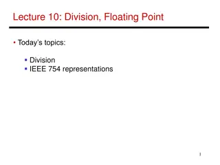
Lecture 11: Floating Point, Digital Design Today s topics: FP formats, arithmetic Intro to Boolean functions 1
Value inf Value NAN Highest value ~2 x 2127 2 special cases up top that use the reserved exponent field of 255 0 255 00 0 0 255 xx .x 0 254 11 .1 Value 1 0 127 00 0 Exponent field < 127, i.e., after subtracting bias, they are negative exponents, representing numbers < 1 Smallest Norm ~2 x 2-126 Largest Denorm ~1 x 2-126 Smallest Denorm ~2-149 0 0..01 00 0 0 0..00 11 1 0 0..00 00 1 Special case with exponent field 0, used to represent denorms, that help us gradually approach 0 Value 0 0 00..0 00 0 Same rules as above, but the sign bit is 1 Same magnitudes as above, but negative numbers 2
Example 2 Final representation: (-1)S x (1 + Fraction) x 2(Exponent Bias) Represent 36.90625ten in single-precision format 36 / 2 = 18 rem 0 18 / 2 = 9 rem 0 9 / 2 = 4 rem 1 4 / 2 = 2 rem 0 2 / 2 = 1 rem 0 1 / 2 = 0 rem 1 0.90625 x 2 = 1.81250 0.8125 x 2 = 1.6250 0.625 x 2 = 1.250 0.25 x 2 = 0.50 0.5 x 2 = 1.00 0.0 x 2 = 0.0 0.90625 is 0.1110100 0 36 is 100100 3
Example 2 Final representation: (-1)S x (1 + Fraction) x 2(Exponent Bias) We ve calculated that 36.90625ten= 100100.1110100 0 in binary Normalized form = 1.001001110100 0 x 25 (had to shift 5 places to get only one bit left of the point) The sign bit is 0 (positive number) The fraction field is 001001110100 0 (the 23 bits after the point) The exponent field is 5 + 127 (have to add the bias) = 132, which in binary is 10000100 The IEEE 754 format is 0 10000100 001001110100 ..0 sign exponent 23 fraction bits 4
Remember: +127 True exponent Exponent in register -127 5
Examples Final representation: (-1)S x (1 + Fraction) x 2(Exponent Bias) Represent -0.75ten in single and double-precision formats Single: (1 + 8 + 23) Remember: +127 True exponent Exponent in register -127 Double: (1 + 11 + 52) What decimal number is represented by the following single-precision number? 1 1000 0001 01000 0000 6
Examples Final representation: (-1)S x (1 + Fraction) x 2(Exponent Bias) Represent -0.75ten in single and double-precision formats Single: (1 + 8 + 23) 1 0111 1110 1000 000 Double: (1 + 11 + 52) 1 0111 1111 110 1000 000 What decimal number is represented by the following single-precision number? 1 1000 0001 01000 0000 -5.0 7
FP Addition Consider the following decimal example (can maintain only 4 decimal digits and 2 exponent digits) 9.999 x 101 + 1.610 x 10⁻¹ Convert to the larger exponent: 9.999 x 101 + 0.016 x 101 Add 10.015 x 101 Normalize 1.0015 x 10² Check for overflow/underflow Round 1.002 x 10² Re-normalize 8
FP Addition Consider the following decimal example (can maintain only 4 decimal digits and 2 exponent digits) 9.999 x 101 + 1.610 x 10⁻¹ Convert to the larger exponent: 9.999 x 101 + 0.016 x 101 Add 10.015 x 101 Normalize 1.0015 x 10² Check for overflow/underflow Round 1.002 x 10² Re-normalize If we had more fraction bits, these errors would be minimized 9
FP Addition Binary Example Consider the following binary example 1.010 x 21 + 1.100 x 23 Convert to the larger exponent: 0.0101 x 23 + 1.1000 x 23 Add 1.1101 x 23 Normalize 1.1101 x 23 Check for overflow/underflow Round Re-normalize IEEE 754 format: 0 10000010 11010000000000000000000 10
FP Multiplication Similar steps: Compute exponent (careful!) Multiply significands (set the binary point correctly) Normalize Round (potentially re-normalize) Assign sign 11
MIPS Instructions The usual add.s, add.d, sub, mul, div Comparison instructions: c.eq.s, c.neq.s, c.lt.s . These comparisons set an internal bit in hardware that is then inspected by branch instructions: bc1t, bc1f Separate register file $f0 - $f31 : a double-precision value is stored in (say) $f4-$f5 and is referred to by $f4 Load/store instructions (lwc1, swc1) must still use integer registers for address computation 12
Code Example float f2c (float fahr) { return ((5.0/9.0) * (fahr 32.0)); } (argument fahr is stored in $f12) lwc1 $f16, const5 lwc1 $f18, const9 div.s $f16, $f16, $f18 lwc1 $f18, const32 sub.s $f18, $f12, $f18 mul.s $f0, $f16, $f18 jr $ra 13
Fixed Point FP operations are much slower than integer ops Fixed point arithmetic uses integers, but assumes that every number is multiplied by the same factor Example: with a factor of 1/1000, the fixed-point representations for 1.46, 1.7198, and 5624 are respectively 1460, 1720, and 5624000 More programming effort and possibly lower precision for higher performance 14
Subword Parallelism ALUs are typically designed to perform 64-bit or 128-bit arithmetic Some data types are much smaller, e.g., bytes for pixel RGB values, half-words for audio samples Partitioning the carry-chains within the ALU can convert the 64-bit adder into 4 16-bit adders or 8 8-bit adders A single load can fetch multiple values, and a single add instruction can perform multiple parallel additions, referred to as subword parallelism 15
Digital Design Basics Two voltage levels high and low (1 and 0, true and false) Hence, the use of binary arithmetic/logic in all computers A transistor is a 3-terminal device that acts as a switch V V 0 V V 0 Conducting Non-conducting 0 0 16
Logic Blocks A logic block has a number of binary inputs and produces a number of binary outputs the simplest logic block is composed of a few transistors A logic block is termed combinational if the output is only a function of the inputs A logic block is termed sequential if the block has some internal memory (state) that also influences the output A basic logic block is termed a gate (AND, OR, NOT, etc.) We will only deal with combinational circuits today 17
Truth Table A truth table defines the outputs of a logic block for each set of inputs Consider a block with 3 inputs A, B, C and an output E that is true only if exactly 2 inputs are true A B C E 18
Truth Table A truth table defines the outputs of a logic block for each set of inputs Consider a block with 3 inputs A, B, C and an output E that is true only if exactly 2 inputs are true A B C E 0 0 0 0 0 0 1 0 0 1 0 0 0 1 1 1 1 0 0 0 1 0 1 1 1 1 0 1 1 1 1 0 Can be compressed by only representing cases that have an output of 1 19