Understanding Advanced Analog IC Design and Filtering Techniques
Exploring the world of Advanced Analog IC Design through the concepts of continuous-time active filters, frequency domains, time domains, filter specifications, and examples of passive RLC filters. Delve into the intricacies of different filter types, such as low-pass, high-pass, and band-pass, to enhance your knowledge in analog IC design.

Uploaded on Sep 26, 2024 | 0 Views
Download Presentation

Please find below an Image/Link to download the presentation.
The content on the website is provided AS IS for your information and personal use only. It may not be sold, licensed, or shared on other websites without obtaining consent from the author. Download presentation by click this link. If you encounter any issues during the download, it is possible that the publisher has removed the file from their server.
E N D
Presentation Transcript
Advanced Analog IC Design EECT 7326 Prof. Y. Chiu Fall 2015 Continuous-Time Active Filters 1
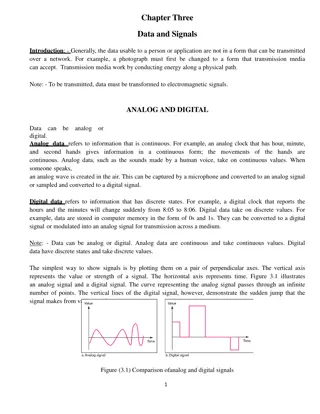
Advanced Analog IC Design EECT 7326 Prof. Y. Chiu Fall 2015 Introduction Filtering: most common linear time-invariant (LTI) signal processing function selecting the signal bandwidth of interest (in reality neither linear nor time-invariant) Categories: continuous time (CT), discrete time (DT) analog filter, digital filter (will focus on CT analog filters for this course) Frequency domain: low-pass (LP), high-pass (HP), band-pass (BP) Time domain: impulse response, FIR, IIR 2
Advanced Analog IC Design EECT 7326 Prof. Y. Chiu Fall 2015 Simple RC Filter s-plane j R Vi C Vo 0 sp=- 0 1 V V 1 1 sC ( ) s = H(s)= = s =- =-RC o 1 p 0 1+sRC R+sC i Continuous-time, 1st-order, one real pole, low-pass 3
Advanced Analog IC Design EECT 7326 Prof. Y. Chiu Fall 2015 Simple RC Filter Frequency response Impulse response t 1 |H(j )| - h(t)= e for t 0, -20dB/dec -6dB/oct 1 1 =RC, =RC 0 0 0 H(t) e-t/ H(j ) 1/ 0 0 -45 0 t -90 4
Advanced Analog IC Design EECT 7326 Prof. Y. Chiu Fall 2015 General Filter Specs |H(j )| Ideal LPF: 1 Non-causal Infinite complexity 0 0 |H(j )| p - passband ripple (< 1dB) 0dB More realistic: Stopband Magnitude response p, s, p, and s Phase response s - stopband attenuation Passband 0 p s Transition band 5
Advanced Analog IC Design EECT 7326 Prof. Y. Chiu Fall 2015 Example: 2nd-order VTF V V b ( ) s = H(s)= o s +as+b 2 i Continuous-time Where are the poles? (complex conjugate poles for maximum flatness) Low-pass, high-pass, or band-pass? 6
Advanced Analog IC Design EECT 7326 Prof. Y. Chiu Fall 2015 Passive RLC Filter R L 1 LC R L H(s)= 1 Vi C Vo s +s + 2 LC No active component (low power) Inductors are bulky and expensive to realize in IC s Values of R, L, and C will not track each other 7
Advanced Analog IC Design EECT 7326 Prof. Y. Chiu Fall 2015 Active OP-RC Filter R2 It s active Inductor-less Area efficient Values of R s and C s and their time co. s won t track each other may lead to RC time constant variations of as high as 20% RC time constant enters the VTF in product form can be tuned for accuracy R4 CA R CB R1 R R3 Vi Vo Assuming ideal op amps, 1 R R C C 1 R C H(s)=- 1 3 A B 1 s +s + 2 R R C C 4 B 2 3 A B 8
Advanced Analog IC Design EECT 7326 Prof. Y. Chiu Fall 2015 Continuous-Time Integrator C2 R1 Vi Vo Assuming ideal op amp, t V V 1 s R C 1 1 ( ) ( ) s =- ( ) t =- ( ) d H s = v v o o in R C i 1 2 1 2 - 9
Advanced Analog IC Design EECT 7326 Prof. Y. Chiu Fall 2015 Cascade Filter Design Biquads 10
Advanced Analog IC Design EECT 7326 Prof. Y. Chiu Fall 2015 Cascade Filter Design j For a real-coefficient H(s): s-plane ( ) ( ) s H ( ) s ( ) H s =H H s bq1 bq2 s 0 2nd-order 1st-order K s +K s+K s + Q 2 ( ) s =- H Biquad: 2 1 0 bq s+ 2 2 0 0 The leading minus sign in Hbq(s) is only for convenience 11
Advanced Analog IC Design EECT 7326 Prof. Y. Chiu Fall 2015 Special Cases of Biquad K s +K s+K s + Q 2 ( ) s =- H 2 1 0 bq s+ 2 2 0 0 1) If K =K =0 LPF 2 1 2) If K =K =0 HPF 0 1 3) If K =K =0 BPF 0 2 4) If K =0 BSF 1 12
Advanced Analog IC Design EECT 7326 Prof. Y. Chiu Fall 2015 Q Factor of Poles s j p Q= = 0 2 2 sp p p j p 2 0 1 2 p = 1+ p 0 p s-plane = s = + 2 2 0 p p p 13
Advanced Analog IC Design EECT 7326 Prof. Y. Chiu Fall 2015 Signal Flow Graph (SFG) for Biquad Q 1 s 1 s ( ) V =- K +K s V + V - V 0 V V K s +K s+K s + Q 2 o 1 2 i o 0 m ( ) s = H =- o 2 1 0 bq K s+ 2 2 0 i V =- V + V 0 0 m i 0 o 0 0 0/Q 1 K0/ 0 1 1 - 0 1 1 1 Vi -1/s -1/s Vo 1 Vm K1+K2s Note: the partition of the biquadratic VTF is not unique 14
Advanced Analog IC Design EECT 7326 Prof. Y. Chiu Fall 2015 OP-RC Implementation 1/ 0 Q/ 0 CA=1 CB=1 0/K0 -1/ 0 Vm Vi Vo 1/K1 K2 K s +K s+K s + Q 2 ( ) s =- H 2 1 0 bq s+ 2 2 0 0 15
Advanced Analog IC Design EECT 7326 Prof. Y. Chiu Fall 2015 Alternative SFG for Biquad Recast Hbq(s): 1 s 1 s ( ) V =- K sV - V o 2 i 0 m V V K s +K s+K s + Q 2 ( ) s = H =- o 2 1 0 bq K K s Q s+ 2 2 0 V =- + s V + + V i 0 1 0 m i 0 o 0 0 0+s/Q 1 K0/ 0+sK1/ 0 1 1 - 0 1 1 1 Vi -1/s -1/s Vo 1 Vm K2s 16
Advanced Analog IC Design EECT 7326 Prof. Y. Chiu Fall 2015 Alternative OP-R-C Prototype 1/ 0 1/Q K1/ 0 CA=1 CB=1 -1/ 0 Vm Vi Vo 0/K0 K2 K s +K s+K s + Q 2 ( ) s =- H 2 1 0 bq s+ 2 2 0 0 17
Advanced Analog IC Design EECT 7326 Prof. Y. Chiu Fall 2015 Cascade Filter Design j For a real-coefficient H(s): s-plane ( ) ( ) s H ( ) s ( ) H s =H H s bq1 bq2 s 0 2nd-order 1st-order 1st-order Section Biquad 1 ( 01, Q1) Biquad 2 ( 02, Q2) Order of cascade determines the signal dynamic range Optimized using engineering rule of thumb or thru simulation 18
Advanced Analog IC Design EECT 7326 Prof. Y. Chiu Fall 2015 Biquad Cascade Filter Design Most flexible arrangement of cascade filter design Allow independent, non-interacting control of ( 0, Q) for pole pairs Easy design Components need to be scaled for maximum DR and minimum component spread Pass-band sensitivity to capacitance variation is finite Ladder filter can achieve zero sensitivity 19
Advanced Analog IC Design EECT 7326 Prof. Y. Chiu Fall 2015 Scaling of Active Filter 20
Advanced Analog IC Design EECT 7326 Prof. Y. Chiu Fall 2015 Typical Active Multi-Stage Filters Fi Fj S2i Sij V2 Vi Vin S1i S1j Vout V2 V1 V1 A2 Vi Vj Ai Aj V1 A1 1st-order Section Biquad 1 ( 01, Q1) Biquad 2 ( 02, Q2) Initial component values may not be optimal... 21
Advanced Analog IC Design EECT 7326 Prof. Y. Chiu Fall 2015 Freq. Response of Internal Nodes Vi |H(j )| V1 Vo,max of op amps Vj 0 i j Internal signal swings need to be large to max SNR But not too large such that op amps saturate (producing distortion) 22
Advanced Analog IC Design EECT 7326 Prof. Y. Chiu Fall 2015 DR Scaling of ith Integrator (Vi) Sim Fi Fj S2i Sij V2 Vin S1i Vout V2 V1 A2 Vi Vj Ai Aj V1 Sik A1 First find out the peak value of Vi( ), mostly done with simulation Then find out the ratio ki = Vi,peak/Vo,max Multiply all capacitors connecting at Vi by ki: Fi Fi*ki, Sij Sij*ki, Divide all resistors connecting at Vi by ki: Fi Fi*ki, Sij Sij*ki, Repeat for all internal nodes 23
Advanced Analog IC Design EECT 7326 Prof. Y. Chiu Fall 2015 After DR Scaling |H(j )| V1 Vi Vj Vo,max of op amps 0 i j Max internal signal swings all line up to Vo,max 24
Advanced Analog IC Design EECT 7326 Prof. Y. Chiu Fall 2015 Scaling for Min. Component Spread Sim Fi Fj S2i Sij V2 Vin S1i Vout V2 V1 Xi A2 Vi Vj Ai Aj V1 Sik A1 Find out the smallest cap/res connected to Xi the summing node of Ai determine the optimum scaling factor mi to minimize spread Multiply all capacitors connected to Xi by mi: Fi Fi*mi, Sji Sji*mi, Divide all resistors connected to Xi by mi: Fi Fi*mi, Sji Sji*mi, Repeat for all integrators 25
Advanced Analog IC Design EECT 7326 Prof. Y. Chiu Fall 2015 Scaling of Active Filter DR and min spread scaling do not take op-amp loading into account lots of work if individual op amps are sized to meet the settling time constraint Upon the completion of scaling, simulation needs to be performed on the resulting filter to find out the overall SNR If SNR is lower than the spec, capacitors and op amps need to be scaled up and resistors scaled down to meet the SNR spec (think about how integrated output noise behaves) 26
Advanced Analog IC Design EECT 7326 Prof. Y. Chiu Fall 2015 Ladder Filter Design 27
Advanced Analog IC Design EECT 7326 Prof. Y. Chiu Fall 2015 Motivation Cascade filter design Sensitive to component variations, especially high-Q poles Ladder filter design Achieves zero sensitivity to component variations Discrete CT LC filters with very high-Q poles are built with ladder structures over the years 28
Advanced Analog IC Design EECT 7326 Prof. Y. Chiu Fall 2015 Ladder Filter RS L2 L4 V1 V3 V5 I2 I4 Vin C1 C3 C5 RL Vout Reactance two-port Doubly terminated reactance two-port network Delivers the optimum power matching in the passband |Vout|/ Zi= 0 for all L s and C s low sensitivity 29
Advanced Analog IC Design EECT 7326 Prof. Y. Chiu Fall 2015 State Space of Ladder Filter RS L2 V1 V3 I2 Vin C1 C3 RL Vout V -V 1 -V =- -I (1) in R 1 1 2 sC 1 sL 1 sC 1 S Pick V1, -I2, V3 as the state variables for synthesis ( ) -I =- V -V (2) 2 1 3 2 V R V =- -I (3) 3 3 2 3 L 30
Advanced Analog IC Design EECT 7326 Prof. Y. Chiu Fall 2015 Signal Flow Graph (SFG) -I2 1/RS 1 1 Vin -1 sC1 -1 sL2 -1 sC3 1/RS 1/RL -1 -1 -V1 V3 V -V 1 -V =- -I (1) in R 1 1 2 sC 1 sL 1 sC 1 S ( ) -I =- V -V (2) 2 1 3 2 V R V =- -I (3) 3 3 2 3 L 31
Advanced Analog IC Design EECT 7326 Prof. Y. Chiu Fall 2015 CT OP-RC Ladder Filter RS Vin 1 1 -I2 RS C1 L2 C3 RL -1 -1 -V1 V3 Three free state variables three op amps A.k.a the leapfrog ladder structure 32
Advanced Analog IC Design EECT 7326 Prof. Y. Chiu Fall 2015 Transmission Zeros Elliptic LPF 10 C2 0 RS L2 V1 V3 -10 -20 I2 -30 Vin C1 C3 RL Vout dB -40 -50 -60 -70 1 -80 = 6 7 10 10 z L C Freq 2 2 33
Advanced Analog IC Design EECT 7326 Prof. Y. Chiu Fall 2015 Transmission Zeros ( ( ) ( ) ( ( ) I I into node 1 =sC into node 3 =sC V -V =sC V +sC V -V =sC V +sC -V -V C2 IC2 IC2' C 2 3 1 2 3 2 1 2 V1 V3 ) ( ) ) C 2 1 3 2 1 2 3 2 sC2 V3 sC2 V1 RS L2 V1 V3 I2 Vin C2 C1 C3 C2 RL Vout 34
Advanced Analog IC Design EECT 7326 Prof. Y. Chiu Fall 2015 Modified SFG with Derivatives sC2 sC2 -I2 1/RS 1 1 Vin -1 -1 sL2 -1 1/RS 1/RL s(C1+C2) s(C2+C3) -1 -1 -V1 V3 35
Advanced Analog IC Design EECT 7326 Prof. Y. Chiu Fall 2015 OP-RC Ladder Filter w/ Derivatives C2 C2 RS Vin 1 1 -I2 RS C1+C2 L2 C2+C3 RL -1 -1 -V1 V3 Derivative input paths implemented with capacitors 36
Advanced Analog IC Design EECT 7326 Prof. Y. Chiu Fall 2015 Other Active Filters 37
Advanced Analog IC Design EECT 7326 Prof. Y. Chiu Fall 2015 Tow-Thomas Biquad R3 R1 C1 R8 C2 Vout Low sensitivity R4 R7 R2 Non-interactive tuning property Vin R6 R5 [1] P. E. Fleischer and J. Tow, "Design formulas for biquad active filters using three operational amplifiers, Proceedings of the IEEE, vol. 61, pp. 662-3, issue 5, 1973. 38
Advanced Analog IC Design EECT 7326 Prof. Y. Chiu Fall 2015 Design Equations for Tow-Thomas R R R R 1 R R R R R 1 s + - s+ 2 8 8 1 8 8 R C R R R C C R ms +cs+d s +as+b 2 V ( ) ( ) s =- H s = 6 1 1 6 4 7 3 5 7 1 2 out V 1 2 s + s+ 2 8 in R C R R C C R 1 1 2 3 1 2 7 k bC 1 m 1 1 1 bC 1 k 1 R = ,R = ,R = ,R = , 1 ( ) 1 2 3 4 aC k dC 1 2 k k ma-c C 1 2 1 2 1 b R = ,R = R ,R =k R . 1 5 6 8 7 2 8 2 Note: C1, C2, k1, k2, R8 are free parameters 39
Advanced Analog IC Design EECT 7326 Prof. Y. Chiu Fall 2015 Sallen-Key LPF C1 B R1 R2 Vin Vout K A C2 OP-RC active filters are ideally insensitive to bottom-plate stray caps Sallen-Key is sensitive to bottom-plate parasitics at node A and B 40
Advanced Analog IC Design EECT 7326 Prof. Y. Chiu Fall 2015 Design Equations for SK LPF C1 B R1 R2 Vin Vout K A C2 1 = , 0 R C R C G Q 2 1 1 2 2 ( ) H s = 0 s+ 1 Q= , 0 1 1-K R C s + 2 2 0 + + 0 R C R C 1 1 2 1 2 2 G=K. 41
Advanced Analog IC Design EECT 7326 Prof. Y. Chiu Fall 2015 Sallen-Key BPF R2 R1 C2 A B Vin Vout K C1 R3 Still sensitive to parasitic capacitance at node A and B 42
Advanced Analog IC Design EECT 7326 Prof. Y. Chiu Fall 2015 Design Equations for SK BPF R2 R1 C2 A B Vin Vout K C1 R3 R +R = , 1 2 0 R R C R C 3 1 1 2 2 Q Q= , 0 G s 0 1 1 1 1-K R C + + + ( ) H s = R C R C R C 1 1 3 1 3 2 2 1 Q K s + s+ 2 2 0 0 R C G= . 1 + 1 1 1 1 1-K R C + + R C R C R C 1 1 3 1 3 2 2 1 43
Advanced Analog IC Design EECT 7326 Prof. Y. Chiu Fall 2015 MOSFET-C Active Filter 44
Advanced Analog IC Design EECT 7326 Prof. Y. Chiu Fall 2015 MOSFET Resistor G VGS IDS VDS=VGS-Vth S D VGS S D 0 VDS MOSFET in triode region is a variable resistor Compact, low parasitics compared to large-value resistors 45
Advanced Analog IC Design EECT 7326 Prof. Y. Chiu Fall 2015 MOSFET Resistor W L 1 2 ( ) In trioderegion, I = C V -V V - V 2 DS ox GS th DS DS I V 1 W L ( ) Smallsignal, = = C V -V -V DS ox GS th DS R DS DS W L ( ) = C V -V for V =0 ox GS th DS But the large-signal response is quite nonlinear 46
Advanced Analog IC Design EECT 7326 Prof. Y. Chiu Fall 2015 A Linear (Diff.) MOSFET Resistor VG V 2 V 2 V = V + , V = V - i i 1 ic 2 ic V1 V2 W L W L W L W L 1 2 ( ) 2 In trioderegion, I = C V -V V - V DS ox GS th DS DS 1 2 ( )( ) ( ) 2 = C V -V -V V -V - V -V ox G th 2 1 2 1 2 V 2 1 2 2 = C V -V -V + V - V i ox G th ic i i ( ) = C V -V -V V ox G th ic i MOSFET resistor is linear when driven by balanced differential signals! 47
Advanced Analog IC Design EECT 7326 Prof. Y. Chiu Fall 2015 Rudell VGA + Mixer M9-M15 comprise the CMFB circuit Gain adjustment by varying IGain [2] J. C. Rudell et al., A 1.9-GHz wide-band IF double conversion CMOS receiver for cordless telephone applications, IEEE Journal of Solid-State Circuits, vol. 32, pp. 2071-88, issue 12, 1997. 48
Advanced Analog IC Design EECT 7326 Prof. Y. Chiu Fall 2015 MOSFET-C Integrator VC C C M1 Vi+ Vi- Vo+ Vi+ Vi- Vo+ = Vo- Vo- C C M2 Sources of M1 and M2 are ideally always equal-potential Fully differential circuit rejects the 2nd-order harmonic (and all even-order distortions) Triode resistance significantly depends on process (threshold, mobility, etc.), temperature, and VDD Filter response needs tuning 49
Advanced Analog IC Design EECT 7326 Prof. Y. Chiu Fall 2015 Frequency Tuning 50