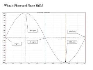
Understanding Oscillator Operation and Phase-Shift Oscillators
The use of positive feedback in a feedback amplifier with closed-loop gain greater than 1 can lead to oscillation, resulting in a varying output signal. Different types of oscillators, such as sinusoidal and pulse oscillators, are discussed along with the Barkhausen criterion for oscillation. The concept of feedback equations and noise signal triggering oscillations are also explored. Additionally, the functionality of phase-shift oscillators in generating oscillations is elaborated upon.
- Oscillator Operation
- Phase-Shift Oscillators
- Positive Feedback
- Barkhausen Criterion
- Feedback Equations

Download Presentation

Please find below an Image/Link to download the presentation.
The content on the website is provided AS IS for your information and personal use only. It may not be sold, licensed, or shared on other websites without obtaining consent from the author. Download presentation by click this link. If you encounter any issues during the download, it is possible that the publisher has removed the file from their server.
E N D
Presentation Transcript
OSCILLATOR OPERATION Lecture 10 page
OSCILLATOR OPERATION The use of positive feedback that results in a feedback amplifier having closed-loop gain |Af| greater than 1 and satisfies the phase conditions will result in operation as an oscillator circuit. An oscillator circuit then provides a varying output signal. If the output signal varies sinusoidally, the circuit is referred to as a sinusoidal oscillator. If the output voltage rises quickly to one voltage level and later drops quickly to another voltage level, the circuit is generally referred to as a pulse or square-wave oscillator.
Fig. 18.18, When the switch at the amplifier input is open, no oscillation occurs. Consider that we have a imaginary voltage at the amplifier input (Vi). This results in an output voltage Vo = AVi after the amplifier stage and in a voltage Vf = (AVi) after the feedback stage. where A is referred to as the loop gain. the base amplifier and feedback network provide A of a correct magnitude and phase, Vf can be made equal to Vi o when the switch is closed and imaginary voltage Vi is removed o circuit will continue operating (the feedback voltage is sufficient to drive the amplifier) o and feedback circuits resulting in a proper input voltage to sustain the loop operation.
Barkhausen criterionfor oscillation The output waveform will still exist after the switch is closed if the condition is met A=1 This is known as the Barkhausen criterionfor oscillation. In reality, no input signal is needed to start the oscillator going. Only the condition A=1 must be satisfied for self-sustained oscillations to result. In practice, A > 1 system is started oscillating by amplifying noise voltage. The resulting waveforms are never exactly sinusoidal. the closer the value Ais to exactly 1, the more nearly sinusoidal is the waveform.
Figure 18.19 shows how the noise signal results in a buildup of a steady-state oscillation condition Another way of seeing as an oscillator by basic feedback equation : Af =A/(1+ A). When A = -1 or magnitude 1 at a phase angle of 180 , so, Af = infinite. an infinitesimal signal (noise voltage) can provide a measurable output voltage, and the circuit acts as an oscillator even without an input signal.
PHASE-SHIFT OSCILLATOR An example of an oscillator circuit An idealized version of this circuit is shown inFig. 18.20. For oscillation must A> 1 phase shift around the feedback network is 180 (providing positive feedback). We are considering by a perfect source (zero source impedance) and the output of the feedback network connected with perfect load (infinite load impedance). Practical circuit versions will then be considered.
and the phase shift is 180. For the loop gain A >1 So, A > 20
the values of R and C to provide (at a specific frequency) 60-phase shift per section for three sections, resulting in a 180 phase shift, as desired. The net result that the total phase shift be 180 is all that is important. If one measured would not provide the same phase shift (overall phase shift is 180 ). If it were desired to obtain exactly a 60 phase shift for each of three stages, then emitter-follower stages would be needed for each RC section to prevent each from being loaded from the following circuit.
FET Phase-Shift Oscillator The amplifier stage is self-biased with a capacitor bypassed source resistor RS and a drain bias resistor RD. The FET device parameters of interest are gm and rd. amplifier gain magnitude is calculated from
Figure 18.21 Practical phase-shift oscillator circuits: (a) FET version
assume as a very good approximation: input impedance (FET) = infinite. This assumption is valid as long as the oscillator operating frequency is low : then capacitive impedances neglected. The output impedance is small compared to the impedance seen looking into the feedback network so that no attenuation due to loading occurs. In practice, these considerations are not always negligible, and the amplifier stage gain is then selected some what larger than the needed factor of 29 to assure oscillator action.
Transistor Phase-Shift Oscillator Fig. 18.21 Practical phase-shift oscillator circuits: b) BJT version. transistor as (active element), an emitter-follower first stage. common-emitter amplifier second stage. If a single transistor stage is desired, the use of voltage-shunt feedback (as shown in Fig. 18.21b) is more suitable. the feedback signal is coupled through the feedback resistor R in series with the amplifier stage input resistance (Ri).
WIEN BRIDGE OSCILLATOR Resistors R1 and R2 and capacitors C1 and C2 form the frequency-adjustment elements, while resistors R3 and R4 form part of the feedback path. The op-amp output is connected as the bridge input at points a and c. The bridge circuit output at points b and d is the input to the op-amp.
Neglecting loading effects of the op-amp input and output impedances, the analysis of the bridge circuit results in If, in particular, the values are R1= R2 = R and C1 = C2 = C, the resulting oscillator frequency is provide sufficient loop gain for the circuit to oscillate at the frequency
TUNED OSCILLATOR CIRCUIT Tuned-Input, Tuned-Output Oscillator Circuits
Colpitts Oscillator FET COLPITTS OSCILLATOR The oscillator frequency can be found to be
Hartley Oscillator If the elements in the basic resonant circuit of Fig. 18.25 are X1 and X2 (inductors) and X3 (capacitor), the circuit is a Hartley oscillator FET HARTLEY OSCILLATOR that inductors L1 and L2 have a mutual coupling, M,which must be taken into account in determining the equivalent inductance for the resonant tank circuit. The circuit frequency of oscillation is then given approximately by
For a circuit as in Fig. below and the following circuit values, calculate the circuit gain and the input and output impedances with and without feedback: RB 650 kohm, RE = 1.4 kohm, RC= 4 = kohm, and = 75. Use VCC 16 V.


")