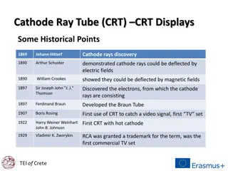
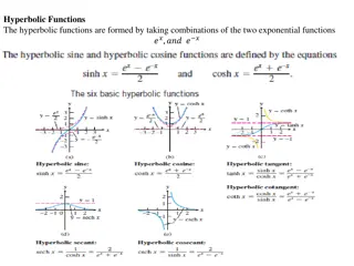
Understanding Oscilloscopes: Functions, Working, and Usage
Oscilloscopes, commonly known as O-Scopes, are essential tools for measuring AC signals with varying frequencies. They help in interpreting waveforms, correcting waveforms in real-time, and working alongside Function Generators. There are analog and digital oscilloscopes, each with specific working mechanisms and features. The block diagram of an oscilloscope simplifies its circuit structure, including vertical amplifiers, time bases, triggers, and displays. Users can control various aspects of the waveform using main controls like Volts/div and Sec/div. Triggering is a crucial step in observing signals accurately. Oscilloscopes play a significant role in lab settings for voltage measurements.

Download Presentation

Please find below an Image/Link to download the presentation.
The content on the website is provided AS IS for your information and personal use only. It may not be sold, licensed, or shared on other websites without obtaining consent from the author. Download presentation by click this link. If you encounter any issues during the download, it is possible that the publisher has removed the file from their server.
E N D
Presentation Transcript
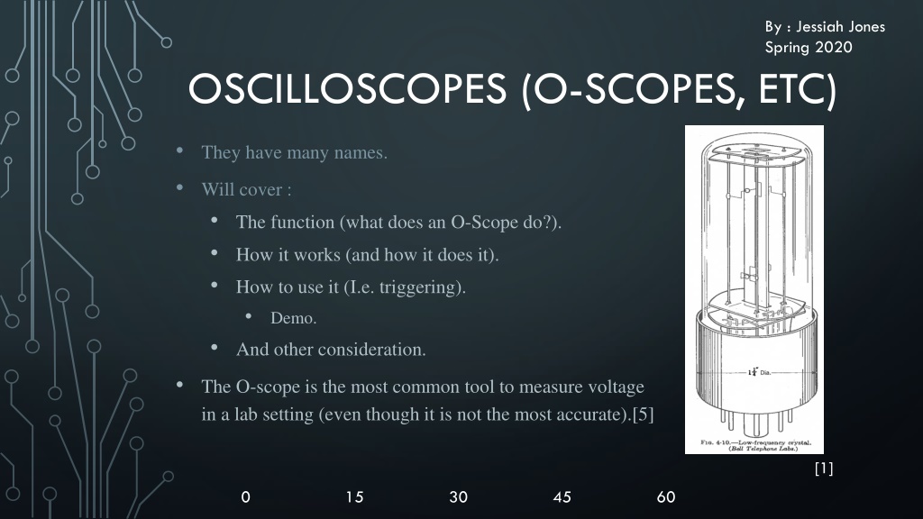
By : Jessiah Jones Spring 2020 OSCILLOSCOPES (O-SCOPES, ETC) They have many names. Will cover : The function (what does an O-Scope do?). How it works (and how it does it). How to use it (I.e. triggering). Demo. And other consideration. The O-scope is the most common tool to measure voltage in a lab setting (even though it is not the most accurate).[5] [1] 0 15 30 45 60
WHAT DOES AN O-SCOPE DO? [1] Used to measure an AC signal with varying frequencies or complex. Necessary for higher frequency AC signals (as low frequency is Approx. DC). Allows for interpretation of a wave form (I.E. sin vs square). [2] Allows for correction or analysis of waveforms on the spot. Using dual-channels. Typically used in conjunction with a Function Generator. [2] 0 15 30 45 60
FUNCTION GENERATOR [1] Creates desired signals with known frequency, amplitude, and period. Most commonly produces a sine wave, but some can also produce Square and Triangle waves. May need other waves. [1] 0 15 30 45 60
HOW DOES IT WORK? Analog O-scopes use an amplifier fed into a CRT, the position of the beam was then a direct comparison to the input voltage. [1] Physical limitations (dead time, dimmer, non-linear, lower precession, smaller view area) Higher bandwidth (later in considerations) has higher brightness Digital O-scopes record, sample and digitize the input signal into a memory. This is then displayed. These have differing bandwidths, prices, errors, etc. [5] 45 0 15 30 60
THE BLOCK DIAGRAM The block diagram aims to simplify the circuits within an O-scope (both analog and digital). It consists of 4 basic circuits [5] The Vertical Amplifier, the time base, the trigger and the display. The Vertical Amplifier magnifies a signal to be easily displayed, while allowing control (such as scale) The display shows the input voltage. The time base is the horizontal scaling system. The trigger is needed to allow an input voltage to be correctly displayed and stabilized. 0 15 30 45 60
HOW TO USE AN O-SCOPE? The main controls directly effect the circuits within the block diagram. On the diagram to the right, Volts/div is related to the vertical amplifier. Sec/div is the timebase, or horizontal system. Measure allows one to measure various aspect of a wave (amp, freq, etc). Cursor allows you to select a specifi point on a wave. Auto set scales the vert./hori. Systems to fit a wave. 0 15 30 [4] 45 60
[6] TRIGGERING Triggering is a necessary step to observe similar repeated waves accurately. This is done by having a trigger level (an input voltage max/min) in which the wave coming into the O-scope is then overlapped onto the old one. Basically, it overlaps one wave onto itself to make the wave more defined (think of it as averaging a wave). This is the most common way of reducing electronic noise (which includes e-mag interference, etc). 0 15 30 45 60
IN LAB EXAMPLES OF USE Speed of Light : We use a dual-channel O-scope attached to a function generator that feeds a pulsing laser. This laser then feeds into a Receiver of varying distance. This signal is then sent back into the O-scope. The difference in phase is then the time it takes for the laser to feed back into the O-scope. The above image is a phase to phase comparison in an O-Scope. The line shows the phase difference. Triggering is meant to make it a line, vs a circle. The length of the line is the time difference. (Unnecessary but cool) 0 15 30 45 60
IN LAB EXAMPLES OF USE Frank-Hertz experiment: Generates an electron beam of differing energy levels. The O-scope is used to line up the energy levels like in the above picture. [8] 0 15 30 45 60
DEMO [4] 0 15 30 45 60
INTERESTING TID-BITS A half wave rectification. 0 15 30 45 60
INTERESTING TID-BITS A square wave 0 15 30 45 60
CONSIDERATIONS : Bandwidth Sampling speed Analysis functions Wrong scaling (full scale uncertainty) Aliasing (digital) trigger 0 15 30 45 60
BIBLIOGRAPHY [1] Various pictures courtesy of Waveforms pg 110, 9, 10, 126 [2] D. Kaplan, et al. Hands-On Electronics 2003 pg 8-14 [3] B. Chance, et al. Waveforms 1949 pg 9-10, 126-129 [4] Picture courtesy of Hands-On Electronics pg 9 [5] J. Murphy Oscilloscope Voltage Measurement 1999 pg (N/A) [6] Picture courtesy of Electronic Notes [7] Picture courtesy of me (Jessiah Jones) [8] Picture courtesy of Dr. Mich. Lab manual.