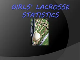
Understanding the Importance of Draw Frames in Spinning Mills


Draw Frame
•
Introduction:
•
It has significant influence on quality of yarn especially evenness.
•
If drawframe is not properly adjusted, yarn strength and
elongation will also be affected.
•
Drawframe is the definitive compensation point for eliminating
errors.
•
Inadequacies in the product leaving the drawframe not only pass
into the yarn, they are actually reinforced by drafting effects
following the drawframe.
•
High-performance drawframes currently produce over 400 kg of
sliver per hour at each delivery.
•
Therefore leveling drawframes are a must for every modern
short staple spinning mill
History of Drafting
•
Lewis Paul is the inventor of drafting by roller.
•
This invention was incorporated by Arkwright in his drawing
frame in 1775.
•
Invention of stop motion by James Smith in 1841 and coiling
system by Jotham and Cheetham made the draw frame into
an acceptable one by industry.
•
Passage of card Sliver Through conventional Draw frame: It
can be divided into three sections;
•
1. Feeding Section,
•
2. Drafting section
•
3. Condensing section
•
For carded yarns the material usually passes two draw frames ,
arranged one after the other and combined to form a group.
•
An exception is the rotor spinning mill where 1 passage is used.
•
However, a second passage after the comber is superfluous,
since this does not produce any improvement in quality. It
usually adversely affects quality due to excessive parallelization
of the fibers. However D/F used has to be a leveling D/F.
1– Normal processing lines; 1. card; 2. drafting module for card;
3. drawframe; 4. combing preparation, 5. combing machine; 6. roving
frame; 7. rotor spinning machine, 8. ring spinning machine
THE TASK OF THE DRAW FRAME
•
Improving evenness over the short, medium and – especially –
long term.
•
Short-wave sliver evenness is not the sole criterion for
evaluating the performance of the draw frame.
•
It is mistake to assume that sliver evenness especially over short
lengths can be significantly improved by using several passages.
•
A second passage brings hardly any improvement and a third
can actually lead to deterioration.
•
It is important to find the optimum rather than seek maximum.
•
Equalizing is always performed by doubling, and can optionally
also be performed by additional autoleveling.
•
The draft and the doublings often have the same value and are
in the range of 6 (short fibers) to 8 (medium and long fibers).
Parallelizing
•
To obtain an optimal value for strength in the yarn
characteristics, the fibers must be arranged parallel in the fiber
strand.
•
D/F fulfills parallelizing by means of the draft, since every
drafting step leads to straightening of the fibers.
•
The value of the draft must be adapted to the material, i.e. to
several fiber parameters, mainly:
•
The staple length;
•
the mass of the fibers;
•
the volume of the strand;
•
the degree of order (parallel disposition).
Blending
•
Doubling also provides a degree of compensation of raw
material variations by blending.
•
At the drawframe, metering of the individual components can
be carried out very simply by selection of the number of slivers
entering the machine.
Dust removal
•
It is important to remove dust to the greatest practical extent
at every possible point within the overall process.
•
Dust ignificant degree when there are high levels of fiber/fiber
or fiber/metal friction.
•
Such friction arises especially on the card and the draw frame.
•
The drawframe is therefore a good dust-removing machine.
•
High-performance drawframes are equipped with appropriate
suction systems
1 : Feed Can, 2. Infeed Roller pair, 3. Drafting rollers, 4:
trumpet, 5: Trumpet, 6: Coiler, 7 Delivery can
Sectional view of a drawframe
Operating Principle
•
Four to eight card or draw frame slivers are fed to the drafting
arrangement (
3
).
•
A feed roller pair (
2
) located above each can (
1
) to enable the feeding
step to be performed in a controlled manner without false drafts.
•
Feed roller pairs are mounted in a creel frame or table and each is
positively driven.
•
The slivers running into the drafting arrangement leave it, after a draft
of 4 to 8, as a web lacking significant cohesion.
•
In order to avoid disintegration of the web, it is condensed into a
sliver immediately after the drafting arrangement.
•
Sliver is then guided through a tube (
4
) via a passage (
6
) of the tube
gear into a can (
7
), in which it must be laid in clean coils.
•
To enable the can to take up as much material as possible, the sliver
is compressed by passing it through calendering rollers or grooved
discs (
5
).
OPERATING DEVICES
•
Creel (sliver feed):
the creel must be designed so that:
•
False drafts are avoided;
•
The machine stops immediately when a sliver break occurs;
•
Sliver breaks can be dealt with easily, comfortably and safely.
•
It is necessary to provide a positively driven roller or roller pair
above each can, one for each sliver.
•
A table with rollers, or simply a line of rollers, can provide the
required guidance.
•
Rollers alone are preferred in rapidly operating high-draft
drawframes, since friction is lower when transport is effected by
means of rolling than when it relies upon sliding.
•
The infeed roller pairs also serve as electrical contact rollers, and
for monitoring the sliver
Different systems of sliver creels
•
Today all drawframes have in-line sliver feed i.e. the feed cans
are arranged in one or (mostly) two rows in the direction of
movement into the machine.
•
Rieter offers a two-row arrangement in “T” form, reducing space
requirements in machine length.
•
Normally, slivers may be fed in from up to eight cans per drawing
head, and the cans may have diameters up to 1 000 mm
Requirements of draw frame
•
simple, uncomplicated construction;
•
stable design with smooth running of the rollers (centricity);
•
a mode of operation producing a high-quality product even at
high running speeds;
•
high degree of flexibility, i.e. suitability for all raw materials,
fibre lengths, sliver hanks, etc., that might be processed in the
short staple spinning mill;
•
optimal control over the movement of the fibers during the
drafting operation;
•
high precision of both operation and adjustment;
•
rapid and simple adjustability of roller spacings and draft
levels;
•
ease of maintenance and cleaning;
•
optimal ergonomic design
Factors that affect the draft
Factors dependent upon the fiber material:
•
mass of fiber in the strand cross section;
•
degree of order of the fibers (parallel disposition);
•
shape of the cross section of the fiber strand;
•
compactness of the fiber strand;
•
adhesion between the fibers dependent upon
–
surface structure,
–
crimp,
–
spin finish,
–
compression of the strand;
•
fiber length;
•
evenness of distribution of fiber lengths (staple form);
•
existing twist in the fiber strand.
Factors that affect the draft
Factors dependent upon the drafting arrangement
•
diameter of the rollers;
•
hardness of the top rollers ;
•
pressure exerted by the top rollers;
•
surface characteristics of the top rollers;
•
fluting of the bottom rollers ;
•
type and form of fiber guiding devices, such as pressure rods,
pin bars, aprons, condenser etc.;
•
clamping distances (roller settings);
•
level of draft;
•
distribution of draft between the various drafting zones.
Suction systems for the drafting arrangement
•
Release of dust occurs almost exclusively in the drafting arrangement and this
should be totally enclosed.
•
The dust-laden air must be extracted by suction.
•
Each roller of the arrangement has an associated cleaning device so that fly
and fibers tending to adhere to the rollers can also be carried away.
•
Trash collections pass into the dust removal system.
•
The air extracted is passed via tubes directly to filters within the
machine and then into the exhaust ducts of the air-conditioning system
or directly into those ducts
4-over-3 drafting arrangement with suction system
The delivery arrangement
•
To avoid disintegration of the web, it must be collected
together in a converging tube immediately after the delivery
roller and guided to the sliver trumpet.
•
Design of the trumpet is very important, as it is responsible for
the proper integration of the edge fibers of the fiber strand
•
The bore of this sliver trumpet must be adapted precisely to
the sliver volume.
•
Condensing
•
After trumpet, the sliver runs between two calender rollers
which are pressed towards each other.
•
Several manufacturers replace the fluted or smooth cylindrical
calender rollers with grooved or stepped rollers.
•
Grooved or stepped rollers can be used simultaneously as
measuring devices for autoleveling systems.
Sliver coiling
•
two rotary movements are required for cycloidal coiling of the
sliver.
•
On the one hand, the rotatable plate must be rotated above the
can, while the can itself must rotate, at a considerably slower
rate, below the plate.
•
A sliver tube is provided on the plate as a fixed part to guide the
sliver from the calender rollers into the can.
•
This tube extends from the center of the plate to its periphery.
•
circumferential velocity at the deposition point is somewhat
higher than the delivery speed
Shape of the sliver tube is no longer
straight, but is now curved exactly to
correspond to the movement of the
coiling sliver.
•
Change gears are provided to permit adjustment to
requirements.
•
Plate is usually driven by toothed belts and the can turntable
by gear wheels or an individual drive.
•
The sliver may be laid in the cans in small coils or in large
coils) depending on the size of the cans.
•
The direction of rotation may also be changed and change
gears are also provided for this purpose.
•
The plate and the can turntable were formerly made to rotate
in the same direction or in opposite directions. The direction
of rotation exerts an influence on the quality of the coiling
operation.
•
The standard can format in short staple spinning was always
cylindrical . Some years ago Rieter introduced a new format: the
rectangular CUBIcan can . Compared with the cylindrical can it has
three major advantages:
•
capacity is increased by about 75%, due not only to the geometry of
the can but also to the elimination of the can spring;
•
it permits optimal utilization of the space available in down-stream
processing;
•
it is suitable for automation
The Rieter RSB-D 40 drawframe
Drawframe with rectangular cans
Can changers
•
Modern high-performance draw frames are fitted with automatic
can changers.
•
These reduce the burden on personnel, enable more machines to
be allocated, reduce the necessity for the operative‘s attendance
at the machine and also increase efficiency.
•
They can be classified into:
•
single-step changers (flying change);
•
multiple-step changers (interrupted change).
•
Single-step changers result in higher machine efficiency since full
cans are replaced by empty ones at full speed.
•
Multiple-step changers result in lower machine efficiency since
the machine must be brought to a stop during the change.
•
modern draw frames are equipped with magazines for up to 8
empty cans.
One or two deliveries per machine
•
The single delivery has clear advantages over the
double delivery drawframe:
•
10% to 20% higher efficiency;
•
higher flexibility when integrated into spinning lines;
•
well suited to automatic transport systems;
•
better accessibility for operation and maintenance;
•
better leveling quality;
•
larger can diameters are possible (up to 1 000 mm for
draw frames without autoleveling).
Aim of autoleveling
•
Main task of autoleveling is to eliminate deviations in
mass.
•
The efficiency of an autoleveling device defined as follows:
“Those machines qualify on which the reaction time is
shorter than the length of the deviation to be eliminated”.
•
This applied to the elimination of long-term deviations.
•
Range of application has shifted toward short-term
regulation, due to the development of servo drives
operating faster and the availability of more efficient
electronics.
•
For modern autoleveling drawframes definition changed
to: “Those machines qualify which allow corrections to be
made as quickly as deviations appear in the incoming
sliver”.
MONITORING DEVICE WITH AUTOLEVELLING SYSTEMS
•
These operate in accordance with either the open-loop or the
closed-loop principle.
•
open-loop control can also compensate variations of short (to
medium) wavelength,
•
closed-loop control can compensate only medium and long-
term variations.
•
This implies that piecings arising from the combing operation
can be partly eliminated with the aid of the open-loop system.
•
Leveling has to be performed so fast that any change in sliver
weight will be corrected while still maintaining a safety reserve
•
Leveling drawframes with closed-loop control can therefore be
used only in the first passage.
•
Compensation is usually effected in a range of ±25%.
Leveling drawframes with open-loop control
•
The total volume of all slivers is measured at the infeed and
adjustment is effected with the appropriate time delay in the
main drafting zone.
•
Detection is usually carried out mechanically (rollers with
grooves, bores or steps) or by capacitive sensors.
•
This system permits very precise leveling of very short lengths
– Leveling drawframe with open-loop control
Leveling drawframes with closed-loop control
•
In this system, the evenness of the sliver delivered is measured.
•
the adjusting point is located after the measuring point, the adjusting
point in the closed-loop control system is located in front of the
measuring point.
•
Measuring has to be performed at very high speeds and with
relatively small fiber masses, making high demands on the sensing
device and signal processing.
•
Adjustment is still made in the main drafting zone.
•
Mechanical or pneumatic sensing devices are generally used.
Leveling drawframe with closed-loop control
Correction length
•
If there is a sudden deviation from the set volume as the material
passes through, a corresponding signal is sent to a regulating device to
correct the fault. Owing to the mass inertia of the system,
compensation cannot be effected suddenly, but must be carried out by
gradual adjustment.
•
A certain time (
I
) elapses before the sliver delivered has returned to the
set volume. During this time, faulty sliver is still being produced,
although the deviation is being steadily reduced. The total length that
departs from the set value is referred to as the correction length (
I
)
The correction length
In closed-loop systems, the correction
length is further increased by the dead
time.
It depends upon the dead time (
II
) and
the correction time (
III
).
Correction length depends upon the
system and the speed of operation
THE RSB AUTOLEVELLING PRINCIPLE
RSB leveling principle
Scanning System
•
Scanning of mass deviation is performed by the grooved
scanning disc and the associated pressure disc.
•
The signals are scanned at short, constant intervals, giving
very exact values of the mass deviations of the infeed slivers.
•
Determination of mass deviation by the pair of rotating
scanning discs enabling the sensor device to employ high
working forces, and thus to scan slivers with different bulk
very accurately.
The leveling process
•
Using the metered signals, the leveling processor
calculates a value of rotation – on the basis of a special
logarithm – for the servo drive.
•
This value is forwarded to the drafting system drive exactly
when the scanned sliver piece arrives at the drafting point
in the main draft zone.
•
The synchronization of the mechanical parts, the drive, the
electronics and the software is therefore very decisive.
•
High-performance drawframes with the appropriate
devices and corresponding synchronization deliver a sliver
with outstanding short-term, medium-term and long-term
evenness.
The leveling operation itself
•
Leveling is performed exclusively by adjustment of the
draft.
•
Main draft is always used because it is larger, and
therefore finer adjustments are possible.
•
Use of the break draft would run the risk of entering
the stick/slip zone.
Draft variation can also be carried out by adjusting
either the infeed or the delivery speed.
•
Adjustment of the infeed speed is generally used, since
lower masses then have to be accelerated and
decelerated at lower speeds.
•
Delivery speed, and hence the production rate, remains
constant.
Advantages of high-performance leveling D/F
•
fewer short-term mass variations in the yarn (CV %);
•
improving the coefficient of variation of yarn
•
fewer yarn imperfections (IPI and Classimat);
•
improving the efficiency of roving frame and spinning machine
by reducing the ends down rates;
•
fewer cuts on the winding machine.
•
In the subsequent process stages
:
•
reduction of ends down rates in weaving preparation and
weaving;
•
even appearance of the finished cloth;
•
reducing the cost for claims by eliminating a remarkable
number of faults
Integrated monitoring
•
If the goal is efficient operation over time, it is necessary to
include monitoring equipment in the overall analysis in
addition to automating the activities of attendants and
transport personnel.
Method of operation
:
•
The
Device operates completely independently of the leveling
system.
•
The position of the sensor is between the drafting arrangement
and the upper can plate.
•
In sensor technology a distinction has to be made between
systems at the delivery roller and at the sliver trumpet.
•
When preset limits are exceeded the machine stops.
A quality monitoring system
•
This continuously controls the sliver mass by means of
movable delivery rollers.
•
A precision sensor unit delivers values of the highest accuracy
and therefore reliability, thus preventing the production of
faulty slivers.
•
Important quality parameters are shown on a monitor, which
is part of the system. These are:
•
sliver count;
•
sliver evenness CV%;
•
length variations for 5 cm,10 cm, 25 cm, 50 cm, 1 m, 3 m, 5 m;
•
detection of thick places ≥ 2cm;
•
current spectrogram;
•
advanced diagram displays, e.g. up to a timeframe of more
than 10 days.
Blending drawframes
•
Every doubling produces simultaneous blending – especially the 6-8
doublings on the drawframe.
•
if cotton and synthetics are to be processed together, operation of
the normal drawframe will no longe be optimal.
•
Blending is good in the longitudinal direction, but is inadequate in the
cross-section.
•
Special blending drawframes have been available for worsted
spinning therefore attempts were made to introduce them into short-
staple spinning mills.
•
This machine (no longer offered for cotton) had four preliminary
drafting arrangements and one downstream drafting arrangement.
•
Each preliminary drafting arrangement processed a separate set of six
slivers.
•
The webs produced were brought together on a table and fed to the
downstream drafting arrangement.
•
Sliver emerging from this point was coiled in cans.
Blending drawframes
•
three passages are almost always needed with normal D/Fs .
•
Two passages suffice when a blending drawframe is used .
•
improved intermixing,
•
Each raw material component can be processed in a drafting
arrangement of its own.
•
However, the disadvantages are serious:
•
five drafting arrangements combined in one machine
•
complexity;
•
cost when 100% cotton is processed (blended yarns not reqd).
Logistics
•
If arranged for individual cans, an automatic can changer and a trolley
loading station are provided.
•
First passage can also be equipped with an interlinking system between
the first and second drawframe passage.
•
The cans are filled and pushed alongside the feed table of the second
passage one by one, forming a spare row.
•
After the feed cans of the second passage run empty, the full spare cans
are pushed into the feed position while the empty cans are simultaneous
pushed out of the feed position into an empty feed row.
Rieter CANlink
From here the cans return to the can
changer of the first passage.
At the final passage the cans from the
can changer are automatically placed
on trolleys to be forwarded to the
next machine.
Technical data of a high-performance D/F
Top Rollers
•
The necessity of top rollers being covered by leather or
synthetic.
•
If the tope rollers were plain, smooth and metallic, the grip
between top and bottom rollers would never be satisfactory.
•
If top rollers were fluted, with thier flutes meshing into each
other, the heavy pressure imposed would crush the fibres.
•
The top rollers are solid and made of cast iron in early days.
The cork or leather was used as a covering, the bare top roller
were plain.
•
With the synthetic cots which are spirally grooved, the bare top
rollers are also given a light spiralling to hold the cot more
firmly.
•
On conventional D/F, a soft cushioned top roller is made to
work in slides or brass bearing
Drafting Speed
•
Over the decades draw frame speed at level of 30 m/min has
been regarded as an almost insuperable barries, to day thier
are designs capable of running at speed of 500 and even 600
m/min. If the sliver weight increase from 4 g/m to 6 g/m
observable during this period is taken into account also,
production will seem to have risen 30 times over from 5 to
150 kg/h.
•
Apart from the machine design, type of raw material
influences the level of drafting speed. It appears that two
effects govern the ultimate product characteristics. Inertial
effect in the drafting have improves the regularity, whereas
stretchability of fibres tends to reduce irregularity. The
ultimate result depends upon the predominent effect of one
over another
•
However, for blended materials, the constituents fibres must
be compatible for avoiding deblending at higher speed.
•
Among the many problems, most commonly occuring
problems are as follows:
•
Roller slippage
•
High tension draft
•
Over parallelization
•
Improper pinion changes
•
Improper roller settings
•
Roller lapping
•
Drafting irregularities.
•
In certain cases, when the weighting on draw frame can not be
increased to the desired level, the roller setting must be made
wider or the sliver must be made lighter.
•
One of the purpose of proper roller setting is to remove hooks
& crimp in the fibres.
•
In order to exercise control over yarn count variation “In-
process length” of fibres is to be measured and according to
the “in-process length” the roller settings are to be maintained.
•
“In-process length” is the length of the fibres in the fibre fleece
as they are coming out of a drafting zone before they are
condensed in the form of sliver. Digital Fibrograph is a popular
instrument to measure the ‘in-process length’ of the fibres in
terms of span length. This instrument is also provided with a
sliver clamp which can be used to measure the span length
both in the forward & backward direction of a fibre fleece
•
Optimum settings are those which gives a minimum difference
in 2.5% span length between forward & backward direction of
the fibre fleece.. Count variation could be expected to be low
only at the optimum setting.
•
For determining the above parameters, when the material pass
through the back zone of the breaker draw framw, the front
zone was made inoperative. The 2.5% span length og the fibre
on the fleece coming out of the back zone was measured in the
forward & backward directions. The trial was repeated for
different setting, to obtain minimum difference between
forward & backward direction. The difference in 2.5% span
length between forward & backward directions & those fibre
fleece is left to be proportional to the quantity of hooked fibres.
•
After optimum setting at the back zone, the trail is repaeted for
front zone. Once the breaker drawframe settings are optimized,
the trial is repaeted for finisher draw frame also.
•
Earlier the roller setting was based on effective length concept.
•
Roller settings (mm) = Effective length + allowance
•
Effective length is derived from a knowledge of the full length
of the fibres in the sample. Span length (mm) obtained from
Digital Fibrograph can be compared with baer Sorter
measurement by using a regression equation as below:
•
Y = mX+C, Y= Effective length (mm), X= 2.5% span lengthv
(mm), m = 1.013, c = 4.39.
•
Studies on the propoerties of yarn and sliver produced using
setting based on effective length and span length concept as
conducted by SITRA are given in Table
An allowance of 8 mm in front zone and 12 mm in the back zone
were maintained in both the drawframes while producing yarn using
effective length concept.
A- Setting based on effective length concept, B Setting based on
effective length concept.
TOP ROLLER PRESSURE
•
Task of the top roller pressure is to ensure the clamping of fibres
which is needed for an optimal drafting process. Roller loading of
older draw frames must be set rather higher than for processing
cotton.
•
Modern draw frames already use high pressures for all fibres so
usually no change of the pressure is required when different
materials are used.
•
Only if high drafting forces occur, higher top roller pressures are
required..
ROLLER SETTING
•
The roller to be adjusted according to the fibre lengths of raw material.
•
Settings which are too narrow cause fibre damage while too wide settings
increase the number of floating fibres and result in higher unevenness of
the sliver.
•
For polyester and polyamide fibres the following roller settings can be
recommended
•
break draft field: fibre cut length +20 %
•
main draft field: fibre cut length +5 to 10 %
Roller settings in 4 over 3 drafting system
ROLLER SETTING
5-over-3 roller drafting system
DRAFT DISTRIBUTION
•
The total draft on a drawing frame is performed in two steps: the break draft and
the main draft).
•
The task of the break draft is to prepare the fibres for the main draft by introducing
pretension into the sliver and by removing the fibre crimp. Usually the break draft is
between 1.28 and 1.7 and depends on several influencing factors. In general it can
be said that higher break drafts are needed with:
•
earlier draw frame passages
•
finer fibres
•
longer fibres
•
pill-free fibres
•
high strength fibres.
•
Since the break draft depends on the material and the total draft is usually set by
the processing system, For high quality products the main draft should however be
limited to the following values:
•
cotton/man-made fibre blends: 3.8
•
viscose: 6.3
•
acrylic (crimped): 5.2
•
polyester (crimped): 6.0
•
polyester (sewing thread): 3.7
•
polypropylene: 6.1
Mechanism of Roller Slip
•
Roller slip can occur when the drafting rollers are correctly
weighted.
•
In a 4 over 4 drafting system, with a draft of 6, the standard
graduated draft distribution is as follows
•
Back zone: 1.15-1.25, Middle Zone: 1.75-1.83, Front Zone: 2.74-
2.85
•
The rollers which are prone to slippage are the second & third top
rollers. When top rollers rotate, an equal & opposite force F1 is
present on the sliver. A force F3 is required to compress and
straighten the fibre. Hence F1 & f3 oppose the movement of
sliver through roller nip.
•
To keep sliver moving, a force F2 is required. When the material is
drafted, there will be drafting forces in the part of each side of
the pair of rollers. The force of nipping the roller must be greater
than drafting force to avoid the slippage.
•
The part of sliver which is in contact with top roller travels
more slowly than that in contact with botom roller.
•
However top roller may also run faster than bottom roller
because of frictional, compressional and drafting forces.
•
The speed of the sliver passing through the nip of two rollers
is usually not equal to that of either of the rollers but it
depends on resulting strain because of the tensile &
compressive forces. The compression & deformation of roller
covering causes these speed differences.
•
Under certain conditions
Draw frames play a crucial role in ensuring the quality and evenness of yarn in spinning mills. Proper adjustment of draw frames is essential for maintaining yarn strength and elongation. Historical inventions and advancements in draw frames have significantly improved their performance. The process of passing carded yarns through draw frames is explained, emphasizing the need for leveling draw frames. The primary task of draw frames is to enhance yarn evenness over different fiber lengths. The importance of parallelizing fibers for optimal yarn strength characteristics is also highlighted.

Download Presentation

Please find below an Image/Link to download the presentation.
The content on the website is provided AS IS for your information and personal use only. It may not be sold, licensed, or shared on other websites without obtaining consent from the author. Download presentation by click this link. If you encounter any issues during the download, it is possible that the publisher has removed the file from their server.
E N D
Presentation Transcript
Draw Frame Introduction: It has significant influence on quality of yarn especially evenness. If drawframe is not properly adjusted, yarn strength and elongation will also be affected. Drawframe is the definitive compensation point for eliminating errors. Inadequacies in the product leaving the drawframe not only pass into the yarn, they are actually reinforced by drafting effects following the drawframe. High-performance drawframes currently produce over 400 kg of sliver per hour at each delivery. Therefore leveling drawframes are a must for every modern short staple spinning mill
History of Drafting Lewis Paul is the inventor of drafting by roller. This invention was incorporated by Arkwright in his drawing frame in 1775. Invention of stop motion by James Smith in 1841 and coiling system by Jotham and Cheetham made the draw frame into an acceptable one by industry. Passage of card Sliver Through conventional Draw frame: It can be divided into three sections; 1. Feeding Section, 2. Drafting section 3. Condensing section
For carded yarns the material usually passes two draw frames , arranged one after the other and combined to form a group. An exception is the rotor spinning mill where 1 passage is used. However, a second passage after the comber is superfluous, since this does not produce any improvement in quality. It usually adversely affects quality due to excessive parallelization of the fibers. However D/F used has to be a leveling D/F.
http://www.rieter.com/typo3temp/pics/Fig_1_2_Normal_processing_line_6705d80f0c.jpghttp://www.rieter.com/typo3temp/pics/Fig_1_2_Normal_processing_line_6705d80f0c.jpg 1 Normal processing lines; 1. card; 2. drafting module for card; 3. drawframe; 4. combing preparation, 5. combing machine; 6. roving frame; 7. rotor spinning machine, 8. ring spinning machine
THE TASK OF THE DRAW FRAME Improving evenness over the short, medium and especially long term. Short-wave sliver evenness is not the sole criterion for evaluating the performance of the draw frame. It is mistake to assume that sliver evenness especially over short lengths can be significantly improved by using several passages. A second passage brings hardly any improvement and a third can actually lead to deterioration. It is important to find the optimum rather than seek maximum. Equalizing is always performed by doubling, and can optionally also be performed by additional autoleveling. The draft and the doublings often have the same value and are in the range of 6 (short fibers) to 8 (medium and long fibers).
Parallelizing To obtain an optimal value for strength in the yarn characteristics, the fibers must be arranged parallel in the fiber strand. D/F fulfills parallelizing by means of the draft, since every drafting step leads to straightening of the fibers. The value of the draft must be adapted to the material, i.e. to several fiber parameters, mainly: The staple length; the mass of the fibers; the volume of the strand; the degree of order (parallel disposition).
Blending Doubling also provides a degree of compensation of raw material variations by blending. At the drawframe, metering of the individual components can be carried out very simply by selection of the number of slivers entering the machine. Dust removal It is important to remove dust to the greatest practical extent at every possible point within the overall process. Dust ignificant degree when there are high levels of fiber/fiber or fiber/metal friction. Such friction arises especially on the card and the draw frame. The drawframe is therefore a good dust-removing machine. High-performance drawframes are equipped with appropriate suction systems
1 : Feed Can, 2. Infeed Roller pair, 3. Drafting rollers, 4: trumpet, 5: Trumpet, 6: Coiler, 7 Delivery can Sectional view of a drawframe
Operating Principle Four to eight card or draw frame slivers are fed to the drafting arrangement (3). A feed roller pair (2) located above each can (1) to enable the feeding step to be performed in a controlled manner without false drafts. Feed roller pairs are mounted in a creel frame or table and each is positively driven. The slivers running into the drafting arrangement leave it, after a draft of 4 to 8, as a web lacking significant cohesion. In order to avoid disintegration of the web, it is condensed into a sliver immediately after the drafting arrangement. Sliver is then guided through a tube (4) via a passage (6) of the tube gear into a can (7), in which it must be laid in clean coils. To enable the can to take up as much material as possible, the sliver is compressed by passing it through calendering rollers or grooved discs (5).
OPERATING DEVICES Creel (sliver feed): the creel must be designed so that: False drafts are avoided; The machine stops immediately when a sliver break occurs; Sliver breaks can be dealt with easily, comfortably and safely. It is necessary to provide a positively driven roller or roller pair above each can, one for each sliver. A table with rollers, or simply a line of rollers, can provide the required guidance. Rollers alone are preferred in rapidly operating high-draft drawframes, since friction is lower when transport is effected by means of rolling than when it relies upon sliding. The infeed roller pairs also serve as electrical contact rollers, and for monitoring the sliver
Different systems of sliver creels Today all drawframes have in-line sliver feed i.e. the feed cans are arranged in one or (mostly) two rows in the direction of movement into the machine. Rieter offers a two-row arrangement in T form, reducing space requirements in machine length. Normally, slivers may be fed in from up to eight cans per drawing head, and the cans may have diameters up to 1 000 mm http://www.rieter.com/typo3temp/pics/Fig_3_2_Different_systems_of_s_3a9e7cc2ab.jpg
Requirements of draw frame simple, uncomplicated construction; stable design with smooth running of the rollers (centricity); a mode of operation producing a high-quality product even at high running speeds; high degree of flexibility, i.e. suitability for all raw materials, fibre lengths, sliver hanks, etc., that might be processed in the short staple spinning mill; optimal control over the movement of the fibers during the drafting operation; high precision of both operation and adjustment; rapid and simple adjustability of roller spacings and draft levels; ease of maintenance and cleaning; optimal ergonomic design
Factors that affect the draft Factors dependent upon the fiber material: mass of fiber in the strand cross section; degree of order of the fibers (parallel disposition); shape of the cross section of the fiber strand; compactness of the fiber strand; adhesion between the fibers dependent upon surface structure, crimp, spin finish, compression of the strand; fiber length; evenness of distribution of fiber lengths (staple form); existing twist in the fiber strand.
Factors that affect the draft Factors dependent upon the drafting arrangement diameter of the rollers; hardness of the top rollers ; pressure exerted by the top rollers; surface characteristics of the top rollers; fluting of the bottom rollers ; type and form of fiber guiding devices, such as pressure rods, pin bars, aprons, condenser etc.; clamping distances (roller settings); level of draft; distribution of draft between the various drafting zones.
Suction systems for the drafting arrangement Release of dust occurs almost exclusively in the drafting arrangement and this should be totally enclosed. The dust-laden air must be extracted by suction. Each roller of the arrangement has an associated cleaning device so that fly and fibers tending to adhere to the rollers can also be carried away. Trash collections pass into the dust removal system. The air extracted is passed via tubes directly to filters within the machine and then into the exhaust ducts of the air-conditioning system or directly into those ducts http://www.rieter.com/typo3temp/pics/Fig_10_2_4-over-3_drafting_arr_1d914ca841.jpg 4-over-3 drafting arrangement with suction system
The delivery arrangement To avoid disintegration of the web, it must be collected together in a converging tube immediately after the delivery roller and guided to the sliver trumpet. Design of the trumpet is very important, as it is responsible for the proper integration of the edge fibers of the fiber strand The bore of this sliver trumpet must be adapted precisely to the sliver volume. Condensing After trumpet, the sliver runs between two calender rollers which are pressed towards each other. Several manufacturers replace the fluted or smooth cylindrical calender rollers with grooved or stepped rollers. Grooved or stepped rollers can be used simultaneously as measuring devices for autoleveling systems.
Sliver coiling two rotary movements are required for cycloidal coiling of the sliver. On the one hand, the rotatable plate must be rotated above the can, while the can itself must rotate, at a considerably slower rate, below the plate. A sliver tube is provided on the plate as a fixed part to guide the sliver from the calender rollers into the can. This tube extends from the center of the plate to its periphery. circumferential velocity at the deposition point is somewhat higher than the delivery speed http://www.rieter.com/typo3temp/pics/Fig_11_2_Rieter_Coiler_TRMOS_V_caf1cf3788.jpg Shape of the sliver tube is no longer straight, but is now curved exactly to correspond to the movement of the coiling sliver.
Change gears are provided to permit adjustment to requirements. Plate is usually driven by toothed belts and the can turntable by gear wheels or an individual drive. The sliver may be laid in the cans in small coils or in large coils) depending on the size of the cans. The direction of rotation may also be changed and change gears are also provided for this purpose. The plate and the can turntable were formerly made to rotate in the same direction or in opposite directions. The direction of rotation exerts an influence on the quality of the coiling operation.
The standard can format in short staple spinning was always cylindrical . Some years ago Rieter introduced a new format: the rectangular CUBIcan can . Compared with the cylindrical can it has three major advantages: capacity is increased by about 75%, due not only to the geometry of the can but also to the elimination of the can spring; it permits optimal utilization of the space available in down-stream processing; it is suitable for automation http://www.rieter.com/typo3temp/pics/Fig_13_2_Drawframe_with_rectan_d9804000b7.jpg http://www.rieter.com/typo3temp/pics/Fig_12_2_The_Rieter_RSB-D_40_d_2c283fdf09.jpg The Rieter RSB-D 40 drawframe Drawframe with rectangular cans
Can changers Modern high-performance draw frames are fitted with automatic can changers. These reduce the burden on personnel, enable more machines to be allocated, reduce the necessity for the operative s attendance at the machine and also increase efficiency. They can be classified into: single-step changers (flying change); multiple-step changers (interrupted change). Single-step changers result in higher machine efficiency since full cans are replaced by empty ones at full speed. Multiple-step changers result in lower machine efficiency since the machine must be brought to a stop during the change. modern draw frames are equipped with magazines for up to 8 empty cans.
One or two deliveries per machine The single delivery has clear advantages over the double delivery drawframe: 10% to 20% higher efficiency; higher flexibility when integrated into spinning lines; well suited to automatic transport systems; better accessibility for operation and maintenance; better leveling quality; larger can diameters are possible (up to 1 000 mm for draw frames without autoleveling).
Aim of autoleveling Main task of autoleveling is to eliminate deviations in mass. The efficiency of an autoleveling device defined as follows: Those machines qualify on which the reaction time is shorter than the length of the deviation to be eliminated . This applied to the elimination of long-term deviations. Range of application has shifted toward short-term regulation, due to the development of servo drives operating faster and the availability of more efficient electronics. For modern autoleveling drawframes definition changed to: Those machines qualify which allow corrections to be made as quickly as deviations appear in the incoming sliver .
MONITORING DEVICE WITH AUTOLEVELLING SYSTEMS These operate in accordance with either the open-loop or the closed-loop principle. open-loop control can also compensate variations of short (to medium) wavelength, closed-loop control can compensate only medium and long- term variations. This implies that piecings arising from the combing operation can be partly eliminated with the aid of the open-loop system. Leveling has to be performed so fast that any change in sliver weight will be corrected while still maintaining a safety reserve Leveling drawframes with closed-loop control can therefore be used only in the first passage. Compensation is usually effected in a range of 25%.
Leveling drawframes with open-loop control The total volume of all slivers is measured at the infeed and adjustment is effected with the appropriate time delay in the main drafting zone. Detection is usually carried out mechanically (rollers with grooves, bores or steps) or by capacitive sensors. This system permits very precise leveling of very short lengths http://www.rieter.com/typo3temp/pics/Fig_15_2_Leveling_drawframe_wi_00a153219d.jpg Leveling drawframe with open-loop control
Leveling drawframes with closed-loop control In this system, the evenness of the sliver delivered is measured. the adjusting point is located after the measuring point, the adjusting point in the closed-loop control system is located in front of the measuring point. Measuring has to be performed at very high speeds and with relatively small fiber masses, making high demands on the sensing device and signal processing. Adjustment is still made in the main drafting zone. Mechanical or pneumatic sensing devices are generally used. http://www.rieter.com/typo3temp/pics/Fig_16_2_Leveling_drawframe_wi_be06126c4e.jpg Leveling drawframe with closed-loop control
Correction length If there is a sudden deviation from the set volume as the material passes through, a corresponding signal is sent to a regulating device to correct the fault. Owing to the mass inertia of the system, compensation cannot be effected suddenly, but must be carried out by gradual adjustment. A certain time (I ) elapses before the sliver delivered has returned to the set volume. During this time, faulty sliver is still being produced, although the deviation is being steadily reduced. The total length that departs from the set value is referred to as the correction length (I) In closed-loop systems, the correction length is further increased by the dead time. It depends upon the dead time (II) and the correction time (III). Correction length depends upon the system and the speed of operation The correction length
THE RSB AUTOLEVELLING PRINCIPLE RSB leveling principle
Scanning System Scanning of mass deviation is performed by the grooved scanning disc and the associated pressure disc. The signals are scanned at short, constant intervals, giving very exact values of the mass deviations of the infeed slivers. Determination of mass deviation by the pair of rotating scanning discs enabling the sensor device to employ high working forces, and thus to scan slivers with different bulk very accurately.
The leveling process Using the metered signals, the leveling processor calculates a value of rotation on the basis of a special logarithm for the servo drive. This value is forwarded to the drafting system drive exactly when the scanned sliver piece arrives at the drafting point in the main draft zone. The synchronization of the mechanical parts, the drive, the electronics and the software is therefore very decisive. High-performance drawframes with the appropriate devices and corresponding synchronization deliver a sliver with outstanding short-term, medium-term and long-term evenness.
The leveling operation itself Leveling is performed exclusively by adjustment of the draft. Main draft is always used because it is larger, and therefore finer adjustments are possible. Use of the break draft would run the risk of entering the stick/slip Draft variation can also be carried out by adjusting either the infeed or the delivery speed. Adjustment of the infeed speed is generally used, since lower masses then have to be accelerated and decelerated at lower speeds. Delivery speed, and hence the production rate, remains constant. zone.
Advantages of high-performance leveling D/F fewer short-term mass variations in the yarn (CV %); improving the coefficient of variation of yarn fewer yarn imperfections (IPI and Classimat); improving the efficiency of roving frame and spinning machine by reducing the ends down rates; fewer cuts on the winding machine. In the subsequent process stages: reduction of ends down rates in weaving preparation and weaving; even appearance of the finished cloth; reducing the cost for claims by eliminating a remarkable number of faults
Integrated monitoring If the goal is efficient operation over time, it is necessary to include monitoring equipment in the overall analysis in addition to automating the activities of attendants and transport personnel. Method of operation: TheDevice operates completely independently of the leveling system. The position of the sensor is between the drafting arrangement and the upper can plate. In sensor technology a distinction has to be made between systems at the delivery roller and at the sliver trumpet. When preset limits are exceeded the machine stops.
A quality monitoring system This continuously controls the sliver mass by means of movable delivery rollers. A precision sensor unit delivers values of the highest accuracy and therefore reliability, thus preventing the production of faulty slivers. Important quality parameters are shown on a monitor, which is part of the system. These are: sliver count; sliver evenness CV%; length variations for 5 cm,10 cm, 25 cm, 50 cm, 1 m, 3 m, 5 m; detection of thick places 2cm; current spectrogram; advanced diagram displays, e.g. up to a timeframe of more than 10 days.
Blending drawframes Every doubling produces simultaneous blending especially the 6-8 doublings on the drawframe. if cotton and synthetics are to be processed together, operation of the normal drawframe will no longe be optimal. Blending is good in the longitudinal direction, but is inadequate in the cross-section. Special blending drawframes have been available for worsted spinning therefore attempts were made to introduce them into short- staple spinning mills. This machine (no longer offered for cotton) had four preliminary drafting arrangements and one downstream drafting arrangement. Each preliminary drafting arrangement processed a separate set of six slivers. The webs produced were brought together on a table and fed to the downstream drafting arrangement. Sliver emerging from this point was coiled in cans.
Blending drawframes three passages are almost always needed with normal D/Fs . Two passages suffice when a blending drawframe is used . improved intermixing, Each raw material component can be processed in a drafting arrangement of its own. However, the disadvantages are serious: five drafting arrangements combined in one machine complexity; cost when 100% cotton is processed (blended yarns not reqd). http://www.rieter.com/typo3temp/pics/Fig_21_2_Principle_of_the_blen_8fb8ea9a32.jpg
Logistics If arranged for individual cans, an automatic can changer and a trolley loading station are provided. First passage can also be equipped with an interlinking system between the first and second drawframe passage. The cans are filled and pushed alongside the feed table of the second passage one by one, forming a spare row. After the feed cans of the second passage run empty, the full spare cans are pushed into the feed position while the empty cans are simultaneous pushed out of the feed position into an empty feed row. http://www.rieter.com/typo3temp/pics/Fig_22_2_Rieter_CANlink_TRMOS_21493a5f87.jpg From here the cans return to the can changer of the first passage. At the final passage the cans from the can changer are automatically placed on trolleys to be forwarded to the next machine. Rieter CANlink
Technical data of a high-performance D/F Delivery speed [m/min] up to 1 100 Production per delivery [kg/h] up to 400 Deliveries per machine 1 or 2 Doublings 4 to 8 Draft up to 12 Delivery hank [ktex] 1.25 to 7 Waste [%] 0.1 to 1
Top Rollers The necessity of top rollers being covered by leather or synthetic. If the tope rollers were plain, smooth and metallic, the grip between top and bottom rollers would never be satisfactory. If top rollers were fluted, with thier flutes meshing into each other, the heavy pressure imposed would crush the fibres. The top rollers are solid and made of cast iron in early days. The cork or leather was used as a covering, the bare top roller were plain. With the synthetic cots which are spirally grooved, the bare top rollers are also given a light spiralling to hold the cot more firmly. On conventional D/F, a soft cushioned top roller is made to work in slides or brass bearing
Drafting Speed Over the decades draw frame speed at level of 30 m/min has been regarded as an almost insuperable barries, to day thier are designs capable of running at speed of 500 and even 600 m/min. If the sliver weight increase from 4 g/m to 6 g/m observable during this period is taken into account also, production will seem to have risen 30 times over from 5 to 150 kg/h. Apart from the machine design, type of raw material influences the level of drafting speed. It appears that two effects govern the ultimate product characteristics. Inertial effect in the drafting have improves the regularity, whereas stretchability of fibres tends to reduce irregularity. The ultimate result depends upon the predominent effect of one over another
However, for blended materials, the constituents fibres must be compatible for avoiding deblending at higher speed. Among the many problems, most commonly occuring problems are as follows: Roller slippage High tension draft Over parallelization Improper pinion changes Improper roller settings Roller lapping Drafting irregularities.
In certain cases, when the weighting on draw frame can not be increased to the desired level, the roller setting must be made wider or the sliver must be made lighter. One of the purpose of proper roller setting is to remove hooks & crimp in the fibres. In order to exercise control over yarn count variation In- process length of fibres is to be measured and according to the in-process length the roller settings are to be maintained. In-process length is the length of the fibres in the fibre fleece as they are coming out of a drafting zone before they are condensed in the form of sliver. Digital Fibrograph is a popular instrument to measure the in-process length of the fibres in terms of span length. This instrument is also provided with a sliver clamp which can be used to measure the span length both in the forward & backward direction of a fibre fleece
Optimum settings are those which gives a minimum difference in 2.5% span length between forward & backward direction of the fibre fleece.. Count variation could be expected to be low only at the optimum setting. For determining the above parameters, when the material pass through the back zone of the breaker draw framw, the front zone was made inoperative. The 2.5% span length og the fibre on the fleece coming out of the back zone was measured in the forward & backward directions. The trial was repeated for different setting, to obtain minimum difference between forward & backward direction. The difference in 2.5% span length between forward & backward directions & those fibre fleece is left to be proportional to the quantity of hooked fibres. After optimum setting at the back zone, the trail is repaeted for front zone. Once the breaker drawframe settings are optimized, the trial is repaeted for finisher draw frame also.
Earlier the roller setting was based on effective length concept. Roller settings (mm) = Effective length + allowance Effective length is derived from a knowledge of the full length of the fibres in the sample. Span length (mm) obtained from Digital Fibrograph can be compared with baer Sorter measurement by using a regression equation as below: Y = mX+C, Y= Effective length (mm), X= 2.5% span lengthv (mm), m = 1.013, c = 4.39. Studies on the propoerties of yarn and sliver produced using setting based on effective length and span length concept as conducted by SITRA are given in Table
Name of Cotton 134 MCU5 DCH-32 Count Spun (Ne) 20 s 40 s 80 s Draw Frame Setting A B A B A B Breaker Front zone 34 34 38 38 41 44 Back zone 38 38 42 44 48 48 Finisher Front zone 34 36 38 40 44 44 Back zone 38 40 42 46 48 50 Cv of Count (%) 3.3 2.8 3.5 2.8 3.6 3.6 CV of Strength (%) 7.2 6.7 7.4 6.5 7.7 6.8 An allowance of 8 mm in front zone and 12 mm in the back zone were maintained in both the drawframes while producing yarn using effective length A- Setting based on effective length concept, B Setting based on effective length concept. concept.
TOP ROLLER PRESSURE Task of the top roller pressure is to ensure the clamping of fibres which is needed for an optimal drafting process. Roller loading of older draw frames must be set rather higher than for processing cotton. Modern draw frames already use high pressures for all fibres so usually no change of the pressure is required when different materials are used. Only if high drafting forces occur, higher top roller pressures are required..
ROLLER SETTING The roller to be adjusted according to the fibre lengths of raw material. Settings which are too narrow cause fibre damage while too wide settings increase the number of floating fibres and result in higher unevenness of the sliver. For polyester and polyamide fibres the following roller settings can be recommended break draft field: fibre cut length +20 % main draft field: fibre cut length +5 to 10 % Roller settings in 4 over 3 drafting system
ROLLER SETTING 5-over-3 roller drafting system
DRAFT DISTRIBUTION The total draft on a drawing frame is performed in two steps: the break draft and the main draft). The task of the break draft is to prepare the fibres for the main draft by introducing pretension into the sliver and by removing the fibre crimp. Usually the break draft is between 1.28 and 1.7 and depends on several influencing factors. In general it can be said that higher break drafts are needed with: earlier draw frame passages finer fibres longer fibres pill-free fibres high strength fibres. Since the break draft depends on the material and the total draft is usually set by the processing system, For high quality products the main draft should however be limited to the following values: cotton/man-made fibre blends: 3.8 viscose: 6.3 acrylic (crimped): 5.2 polyester (crimped): 6.0 polyester (sewing thread): 3.7 polypropylene: 6.1
Mechanism of Roller Slip Roller slip can occur when the drafting rollers are correctly weighted. In a 4 over 4 drafting system, with a draft of 6, the standard graduated draft distribution is as follows Back zone: 1.15-1.25, Middle Zone: 1.75-1.83, Front Zone: 2.74- 2.85 The rollers which are prone to slippage are the second & third top rollers. When top rollers rotate, an equal & opposite force F1 is present on the sliver. A force F3 is required to compress and straighten the fibre. Hence F1 & f3 oppose the movement of sliver through roller nip. To keep sliver moving, a force F2 is required. When the material is drafted, there will be drafting forces in the part of each side of the pair of rollers. The force of nipping the roller must be greater than drafting force to avoid the slippage.
The part of sliver which is in contact with top roller travels more slowly than that in contact with botom roller. However top roller may also run faster than bottom roller because of frictional, compressional and drafting forces. The speed of the sliver passing through the nip of two rollers is usually not equal to that of either of the rollers but it depends on resulting strain because of the tensile & compressive forces. The compression & deformation of roller covering causes these speed differences. Under certain conditions