Wind Power Generation and Wind Farms


Green Power
Generation
Lecture 4
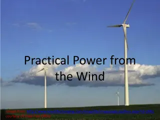
Wind Power
1

2
•
A wind farm is a group of wind turbines in the same location
used for production of electric power
•
A large wind farm may consist of several hundred individual wind
turbines, and cover an extended area of hundreds of square
miles, but the land between the turbines may be used for
agricultural or other purposes
•
A wind farm may also be located offshore
•
Many of the largest operational onshore wind farms are located
in the USA
•
As of November 2010, the Roscoe Wind Farm in Texas is the
largest onshore wind farm in the world at 781.5 MW, followed by
the Horse Hollow Wind Energy Center (735.5 MW), also in Texas
•
As of November 2010, the Thanet Offshore Wind Project in
United Kingdom is the largest offshore wind farm in the world at
300 MW
•
followed by Horns Rev II (209 MW) in Denmark
Wind Farms
3
•
As a general rule, economic wind generators require
windspeed of 10 mph (16 km/h) or greater
•
An ideal location would have a near constant flow of non-
turbulent wind throughout the year, with a minimum
likelihood of sudden powerful bursts of wind
•
An important factor of turbine siting is also access to local
demand or transmission capacity
•
Usually sites are screened on the basis of a wind atlas, and
validated with wind measurements
•
Meteorological wind data alone is usually not sufficient for
accurate siting of a large wind power project
•
Collection of site specific data for wind speed and direction
is crucial to determining site potentialin order to finance the
project
•
Local winds are often monitored for a year or more, and
detailed wind maps constructed before wind generators are
installed
4
•
The wind blows faster at higher altitudes because of the reduced influence
of drag
•
The increase in velocity with altitude is most dramatic near the surface
and is affected by topography, surface roughness, and upwind obstacles
such as trees or buildings
•
Typically, the increase of wind speeds with increasing height follows a
wind profile power law, which predicts that wind speed rises
proportionally to the seventh root of altitude. Doubling the altitude of a
turbine, then, increases the expected wind speeds by 10% and the
expected power by 34%
•
Individual turbines are interconnected with a medium voltage (usually
34.5 kV) power collection system and communications network
•
At a substation, this medium-voltage electrical current is increased in
voltage with a transformer for connection to the high voltage transmission
system
•
Construction of a land-based wind farm requires installation of the
collector system and substation, and possibly access roads to each turbine
site
5
Onshore installations
•
The world's first wind farm – consisting of 20 wind turbines
rated at 30 kilowatts each – was installed on the shoulder of
Crotched Mountain in southern New Hampshire in December,
1980
•
Many of the largest operational onshore wind farms are
located in the USA
•
As of November 2010, the Roscoe Wind Farm is the largest
onshore wind farm in the world at 781.5 MW, followed by the
Horse Hollow Wind Energy Center (735.5 MW)
•
The largest wind farm under construction is the 800 MW Alta
Wind Energy Center in the USA (California)
•
The largest proposed project is the 20,000 MW Gansu Wind
Farm in China
6
•
Onshore
turbine installations in hilly or mountainous regions
tend to be on ridgelines generally three kilometers or more
inland from the nearest shoreline. This is done to exploit the
topographic acceleration
as the wind accelerates over a ridge.
The additional wind speeds gained in this way can increase the
amount of energy produced because more wind is going
through the turbines. Great attention must be paid to the
exact positions of the turbines (a process known as micro-
siting) because a difference of 30 m can sometimes mean a
doubling in output.
7
•
Onshore turbine installations in hilly or mountainous regions
tend to be on ridgelines generally three kilometers or more
inland from the nearest shoreline
•
This is done to exploit the topographic acceleration as the
wind accelerates over a ridge
•
The additional wind speeds gained in this way can increase
the amount of energy produced because more wind is going
through the turbines
•
Great attention must be paid to the exact positions of the
turbines (a process known as micro-siting) because a
difference of 30 m can sometimes mean a doubling in output
8
Offshore installations
1.
Europe is the leader in offshore wind energy, with the first
offshore wind farm being installed in Denmark in 1991
2.
As of 2010, there are 39 offshore wind farms in waters off
Belgium, Denmark, Finland, Germany, Ireland, the
Netherlands, Norway, Sweden and the United Kingdom, with
an operating capacity of 2,396 MW
3.
More than 100 GW (or 100, 000 MW) of offshore projects are
proposed or under development in Europe
4.
The European Wind Energy Association has set of 40 GW
installed by 2020 and 150 GW by 2030
5.
As of November 2010, the Thanet Offshore Wind Project in
United Kingdom is the largest offshore wind farm in the world
at 300 MW, followed by Horns Rev II (209 MW) in Denmark.
9
•
Offshore wind turbines are less obtrusive than turbines on
land, as their apparent size and noise is mitigated by
distance
•
Because water has less surface roughness than land
(especially deeper water), the average wind speed is usually
considerably higher over open water
•
Capacity factors (utilisation rates) are considerably higher
than for onshore locations
10
•
The province of Ontario in Canada is pursuing several
proposed locations in the Great Lakes, including Trillium
Power Wind 1 approximately 20 km from shore and over 400
MW in size
•
Other Canadian projects include one on the Pacific west coast
•
As of 2010, there are no offshore wind farms in the United
States
•
However, projects are under development in wind-rich areas
of the East Coast, Great Lakes, and Pacific coast
11
•
Air is a fluid like any other except that its particles are in gas
form instead of liquid
•
And when air moves quickly, in the form of wind, those
particles are moving quickly
•
Motion means kinetic energy, which can be captured, just like
the energy in moving water can be captured by the turbine in
a hydroelectric dam
•
In the case of a wind-electric turbine, the turbine blades are
designed to capture the kinetic energy in wind
•
The rest is nearly identical to a hydroelectric setup: When the
turbine blades capture wind energy and start moving, they
spin a shaft that leads from the hub of the rotor to a
generator
•
The generator turns that rotational energy into electricity. At
its essence, generating electricity from the wind is all about
transferring energy from one medium to another.
12
•
Wind power all starts with the sun
•
When the sun heats up a certain area of land, the air around
that land mass absorbs some of that heat
•
At a certain temperature, that hotter air begins to rise very
quickly because a given volume of hot air is lighter than an
equal volume of cooler air
•
Faster-moving (hotter) air particles exert more pressure than
slower-moving particles, so it takes fewer of them to
maintain the normal air pressure at a given elevation
•
When that lighter hot air suddenly rises, cooler air flows
quickly in to fill the gap the hot air leaves behind
•
That air rushing in to fill the gap is wind
•
If you place an object like a rotor blade in the path of that
wind, the wind will push on it, transferring some of its own
energy of motion to the blade. This is how a wind turbine
captures energy from the wind. The same thing happens
with a sail boat. When moving air pushes on the barrier of
the sail, it causes the boat to move. The wind has transferred
its own energy of motion to the sailboat.
13
The simplest possible wind-energy turbine consists of three crucial
parts:
•
Rotor blades - The blades are basically the sails of the system;
in their simplest form, they act as barriers to the wind (more
modern blade designs go beyond the barrier method)
•
When the wind forces the blades to move, it has
transferred some of its energy to the rotor
•
Shaft - The wind-turbine shaft is connected to the center of the
rotor. When the rotor spins, the shaft spins as well
•
In this way, the rotor transfers its mechanical, rotational
energy to the shaft, which enters an electrical generator on
the other end
14
•
Generator - At its most basic, a generator is a pretty simple
device
•
It uses the properties of electromagnetic induction to
produce electrical voltage - a difference in electrical charge
•
Voltage is essentially electrical pressure - it is the force that
moves electricity, or electrical current, from one point to
another
•
So generating voltage is in effect generating current
•
A simple generator consists of magnets and a conductor
•
The conductor is typically a coiled wire
•
Inside the generator, the shaft connects to an assembly of
permanent magnets that surrounds the coil of wire
•
In electromagnetic induction, if you have a conductor
surrounded by magnets, and one of those parts is rotating
relative to the other, it induces voltage in the conductor
15
•
When the rotor spins the shaft, the shaft spins the assembly
of magnets, generating voltage in the coil of wire
•
That voltage drives electrical current (typically alternating
current, or AC power) out through power lines for
distribution
16
Modern Wind-power Technology
•
When you talk about modern wind turbines, you're looking at
two primary designs: horizontal-axis and vertical-axis
•
Vertical-axis wind turbines (VAWTs) are pretty rare
•
The only one currently in commercial production is the
Darrieus turbine, which looks kind of like an egg beater.
Vertical-axis wind turbines (left: Darrieus turbine)
17
•
In a VAWT, the shaft is mounted on a vertical axis,
perpendicular to the ground
•
VAWTs are always aligned with the wind, unlike their
horizontal-axis counterparts, so there's no adjustment
necessary when the wind direction changes; but a VAWT can't
start moving all by itself -- it needs a boost from its electrical
system to get started
•
Instead of a tower, it typically uses guy wires for support, so
the rotor elevation is lower. Lower elevation means slower
wind due to ground interference, so VAWTs are generally less
efficient than HAWTs
•
On the upside, all equipment is at ground level for easy
installation and servicing; but that means a larger footprint for
the turbine, which is a big negative in farming areas.
18
Darrieus-design VAWT
19
•
VAWTs may be used for small-scale turbines and for pumping
water in rural areas, but all commercially produced, utility-
scale wind turbines are horizontal-axis wind turbines (HAWTs).
Wind farm in California
20
•
As implied by the name, the HAWT shaft is mounted
horizontally, parallel to the ground
•
HAWTs need to constantly align themselves with the wind
using a yaw-adjustment mechanism
•
The yaw system typically consists of electric motors and
gearboxes that move the entire rotor left or right in small
increments
•
The turbine's electronic controller reads the position of a
wind vane device (either mechanical or electronic) and
adjusts the position of the rotor to capture the most wind
energy available
•
HAWTs use a tower to lift the turbine components to an
optimum elevation for wind speed (and so the blades can
clear the ground) and take up very little ground space since
almost all of the components are up to 260 feet (80 meters)
in the air
21
22
Large HAWT components:
•
rotor blades - capture wind's energy and convert it to rotational energy of shaft
•
shaft - transfers rotational energy into generator
•
nacelle - casing that holds:
•
gearbox - increases speed of shaft between rotor hub and generator
•
generator - uses rotational energy of shaft to generate electricity using
electromagnetism
•
electronic control unit (not shown) - monitors system, shuts down turbine in
case of malfunction and controls yaw mechanism
•
yaw controller (not shown) - moves rotor to align with direction of wind
•
brakes - stop rotation of shaft in case of power overload or system failure
•
tower - supports rotor and nacelle and lifts entire setup to higher elevation where
blades can safely clear the ground
•
electrical equipment - carries electricity from generator down through tower and
controls many safety elements of turbine
23
24
•
The two primary aerodynamic forces at work in wind-turbine
rotors are lift, which acts perpendicular to the direction of
wind flow; and drag, which acts parallel to the direction of
wind flow
•
Turbine blades are shaped a lot like airplane wings -- they use
an airfoil design
•
In an airfoil, one surface of the blade is somewhat rounded,
while the other is relatively flat
•
Lift is a pretty complex phenomenon and may in fact may be
difficult to fully grasp
•
But in one simplified explanation of lift, when wind travels
over the rounded, downwind face of the blade, it has to move
faster to reach the end of the blade in time to meet the wind
travelling over the flat, upwind face of the blade (facing the
direction from which the wind is blowing).
25
•
Since faster moving air tends to rise in the atmosphere, the
downwind, curved surface ends up with a low-pressure pocket
just above it
•
The low-pressure area sucks the blade in the downwind
direction, an effect known as "lift“
•
On the upwind side of the blade, the wind is moving slower
and creating an area of higher pressure that pushes on the
blade, trying to slow it down
•
Like in the design of an airplane wing, a high lift-to-drag ratio is
essential in designing an efficient turbine blade
•
Turbine blades are twisted so they can always present an angle
that takes advantage of the ideal lift-to-drag force ratio
26
•
Aerodynamics is not the only design consideration at play in
creating an effective wind turbine
•
Size matters -- the longer the turbine blades (and therefore the
greater the diameter of the rotor), the more energy a turbine
can capture from the wind and the greater the electricity-
generating capacity
•
Generally speaking, doubling the rotor diameter produces a
four-fold increase in energy output
•
In some cases, however, in a lower-wind-speed area, a smaller-
diameter rotor can end up producing more energy than a
larger rotor because with a smaller setup, it takes less wind
power to spin the smaller generator, so the turbine can be
running at full capacity almost all the time
27
•
Tower height is a major factor in production capacity, as well.
The higher the turbine, the more energy it can capture
because wind speeds increase with elevation increase --
ground friction and ground-level objects interrupt the flow of
the wind. Scientists estimate a 12 percent increase in wind
speed with each doubling of elevation.
28
•
Calculating Power
•
To calculate the amount of power a turbine can actually
generate from the wind, you need to know the wind speed at
the turbine site and the turbine power rating
•
Most large turbines produce their maximum power at wind
speeds around 15 meters per second (33 mph)
•
Considering steady wind speeds, it's the diameter of the rotor
that determines how much energy a turbine can generate
•
Keep in mind that as a rotor diameter increases, the height of
the tower increases as well, which means more access to faster
winds
29
30
•
At 33 mph, most large turbines generate their rated power
capacity, and at 45 mph (20 meters per second), most large
turbines shut down
•
There are a number of safety systems that can turn off a
turbine if wind speeds threaten the structure, including a
remarkably simple vibration sensor used in some turbines that
basically consists of a metal ball attached to a chain, poised on
a tiny pedestal
•
If the turbine starts vibrating above a certain threshold, the
ball falls off the pedestal, pulling on the chain and triggering a
shut down
•
Probably the most commonly activated safety system in a
turbine is the "braking" system, which is triggered by above-
threshold wind speeds
31
•
These setups use a power-control system that essentially
hits the brakes when wind speeds get too high and then
"release the brakes" when the wind is back below 45 mph
•
Modern large-turbine designs use several different types
of braking system
•
Pitch control - The turbine's electronic controller
monitors the turbine's power output
•
At wind speeds over 45 mph, the power output will be
too high, at which point the controller tells the blades
to alter their pitch so that they become unaligned with
the wind
•
This slows the blades' rotation. Pitch-controlled
systems require the blades' mounting angle (on the
rotor) to be adjustable.
32
•
Passive stall control - The blades are mounted to the rotor at
a fixed angle but are designed so that the twists in the
blades themselves will apply the brakes once the wind
becomes too fast
•
The blades are angled so that winds above a certain
speed will cause turbulence on the upwind side of the
blade, inducing stall
•
Simply stated, aerodynamic stall occurs when the blade's
angle facing the oncoming wind becomes so steep that it
starts to eliminate the force of lift, decreasing the speed
of the blades
•
Active stall control - The blades in this type of power-control
system are pitchable, like the blades in a pitch-controlled
system
•
An active stall system reads the power output the way a
pitch-controlled system does, but instead of pitching the
blades out of alignment with the wind, it pitches them
to produce stall
33
Calculation Of Wind Power
Calculate the power of the wind hitting your wind turbine
generator
•
1) The power output of a wind generator is proportional to the
area swept by the rotor - i.e. double the
swept area
and the
power output will also double
2) The power output of a wind generator is proportional to the
cube of the wind speed - i.e. double the
wind speed
and the
power output will increase by a factor of eight (2 x 2 x 2)!
The Power of Wind
•
Wind is made up of moving air molecules which have mass -
though not a lot
•
Any moving object with mass carries kinetic energy in an
amount which is given by the equation:
Kinetic Energy = 0.5 x Mass x Velocity
2
34
The Power of Wind
•
Wind is made up of moving air molecules which have mass -
though not a lot. Any moving object with mass carries kinetic
energy in an amount which is given by the equation:
Kinetic Energy = 0.5 x Mass x Velocity
2
•
where the mass is measured in kg, the velocity in m/s, and
the energy is given in joules
•
Air has a known density (around 1.23 kg/m
3
at sea level), so
the mass of air hitting our wind turbine (which sweeps a
known area) each second is given by the following equation:
Mass/sec (kg/s) = Velocity (m/s) x Area (m
2
) x Density (kg/m
3
)
•
where the mass is measured in kg, the velocity in m/s, and
the energy is given in joules.
35
•
Air has a known density (around 1.23 kg/m
3
at sea level), so
the mass of air hitting our wind turbine (which sweeps a
known area) each second is given by the following equation:
Mass/sec (kg/s) = Velocity (m/s) x Area (m
2
) x Density (kg/m
3
)
•
And therefore, the power (i.e. energy per second) in the wind
hitting a wind turbine with a certain swept area is given by
simply inserting the
mass per second
calculation into the
standard kinetic energy equation given above resulting in the
following vital equation:
Power = 0.5 x Swept Area x Air Density x Velocity
3
•
where Power is given in Watts (i.e. joules/second), the Swept
area in square metres, the Air density in kilograms per cubic
metre, and the Velocity in meters per second
36
Betz’ Law
•
Albert Betz was a german physicist who in 1919 concluded
that no wind turbine can convert more than 16/27 (59.3%)
of the kinetic energy of the wind into mechanical energy
turning a rotor
•
To this day this is known as the Betz Limit or Betz' Law
•
This limit has nothing to do with inefficiencies in the
generator, but in the very nature of wind turbines
themselves.
37
•
Wind turbines extract energy by slowing down
the wind
•
For a wind turbine to be 100% efficient it would
need to stop 100% of the wind - but then the
rotor would have to be a solid disk and it would
not turn and no kinetic energy would be
converted
•
On the other extreme, if you had a wind turbine
with just one rotor blade, most of the wind
passing through the area swept by the turbine
blade would miss the blade completely and so the
kinetic energy would be kept by the wind.
38
39
Real World Wind Turbine Power Efficiencies
•
The theoretical maximum power efficiency of
any
design of
wind turbine is 0.59 (i.e. no more than 59% of the energy
carried by the wind can be extracted by a wind turbine)
•
Once you also factor in the engineering requirements of a
wind turbine - strength and durability in particular - the real
world limit is well below the
Betz Limit
with values of 0.35-
0.45 common even in the best designed wind turbines
•
By the time you take into account other ineffiencies in a
complete wind turbine system - e.g. the generator, bearings,
power transmission and so on - only 10-30% of the power of
the wind is ever actually converted into usable electricity
40
•
Horizontal axis wind turbines (HAWT) theoretically have
higher power efficiencies than vertical axis wind turbines
(VAWT) however wind direction is not important for a VAWT
and so no time (and power) is wasted
chasing
the wind
•
In turbulent conditions with rapid changes in wind direction
more electricity will be generated by a VAWT despite its
lower efficiency.
Schematic of fluid flow through a disk-shaped actuator
41
•
Betz's law is a theory about the maximum possible energy
to be derived from a "hydraulic wind engine", or a wind
turbine such as the Éolienne Bollée (patented in 1868), the
Eclipse Windmill (developed in 1867), and the Aermotor
(first appeared in 1888 to pump water for cattle, and is still
in production)
•
Decades before the advent of the modern 3-blade wind
turbine that generates electricity, Betz's law was developed
in 1919 by the German physicist Albert Betz
•
According to Betz's law, no turbine can capture more than
59.3 percent of the kinetic energy in wind
•
The ideal or maximum theoretical efficiency n max (also
called power coefficient) of a wind turbine is the ratio of
maximum power obtained from the wind to the total
power available in the wind
•
The factor 0.593 is known as Betz's coefficient
•
It is the maximum fraction of the power in a wind stream
that can be extracted.
42
•
Three independent discoveries of the turbine efficiency limit
•
The British scientist Lanchester derived the same maximum
already in 1915
•
The leader of the Russian aerodynamic school, Zukowsky also
published the same result for an ideal wind turbine in 1920,
thesame year as Betz did
•
Economic relevance
•
Because some modern wind turbines approach this potential
maximum efficiency, once practical engineering obstacles are
considered, Betz' Law shows a limiting factor for this form of
renewable energy
•
Engineering constraints, energy storage and transmission
losses and other factors mean that even the best modern
turbines may operate at efficiencies substantially below the
Betz Limit
43
Proof
•
It shows the maximum possible energy — known as the Betz
limit — that may be derived by means of an infinitely thin
rotor from a fluid flowing at a certain speed
•
In order to calculate the maximum theoretical efficiency of a
thin rotor (of, for example, a windmill) one imagines it to be
replaced by a disc that withdraws energy from the fluid
passing through it
•
At a certain distance behind this disc the fluid that has
passed through flows with a reduced velocity.
44
Assumptions
1. The rotor does not possess a hub, this is an ideal rotor, with
an infinite number of blades which have no drag. Any resulting
drag would only lower this idealized value.
2. The flow into and out of the rotor is axial. This is a control
volume analysis, and to construct a solution the control volume
must contain all flow going in and out, failure to account for
that flow would violate the conservation equations.
3. This is incompressible flow. The density remains constant,
and there is no heat transfer from the rotor to the flow or vice
versa.
4. The rotor is also massless. No account is taken of angular
momentum imparted to either the rotor or the air flow behind
the rotor, i.e., no account is taken of any wake effect.
45
Application of conservation of mass (continuity equation)
•
Applying conservation of mass to this control volume, the
mass flow rate (the mass of fluid flowing per unit time) is
given by:
•
where
v
1
is the speed in the front of the rotor
•
v
2
is the speed downstream of the rotor
•
v
is the speed at the fluid power device.
•
ρ
is the fluid density,
•
the area of the turbine is given by
S
.
•
The force exerted on the wind by the rotor may be written as
46
•
The work done by the force may be written incrementally as
•
and the power (rate of work done) of the wind is
47
•
Now substituting the force
F
computed above into the power
equation will yield the power extracted from the wind:
•
However, power can be computed another way, by using
the kinetic energy
•
Applying the conservation of energy equation to the
control volume yields
48
•
Looking back at the continuity equation, a substitution for
the mass flow rate yields the following
•
Both of these expressions for power are completely valid,
one was derived by examining the incremental work done
and the other by the conservation of energy
•
Equating these two expressions yields
•
Examining the two equated expressions yields an
interesting result, mainly
49
•
Therefore, the wind velocity at the rotor may be taken as
the average of the upstream and downstream velocities.
•
This is often the most argued against portion of Betz' law,
but as it can be seen from the above derivation, it is indeed
correct.
50
Betz' law and coefficient of performance
•
Returning to the previous expression for power based on
kinetic energy
51
•
Differentiating E (through careful application of the
chain rule) with respect to for a given fluid speed
v
1
and a given area
S
one finds the
maximum
or
minimum
value for E
•
The result is that E reaches maximum value when
•
Note that when they have the same value, E = 0
•
The horizontal axis
reflects the ratio
v
2
/
v
1
,
the vertical axis is the
"power coefficient"
C
p
.
52
•
Substituting this value results in:
•
The work rate obtainable from a cylinder of fluid with
cross sectional area
S
and velocity
v
1
is:
•
The
"power coefficient"
C
p
(=
P
/
P
wind
) has a maximum value of:
C
p.max
=
16/27 = 0.593 (or 59.3%;
•
However, coefficients of performance are usually expressed as a
decimal, not a percentage).
•
Rotor losses are the most significant energy losses in, for example, a
wind mill. It is, therefore, important to reduce these as much as
possible
•
Modern rotors achieve values for
C
p
in the range of 0.4 to 0.5, which is
70 to 80% of the theoretically possible maximum.
53
Points of interest
•
Note that the preceding analysis has no dependence on the
geometry, therefore S may take any form provided that the
flow travels axially from the entrance to the control volume to
the exit, and the control volume has uniform entry and exit
velocities
•
Note that any extraneous effects can only decrease the
performance of the turbine since this analysis was idealized to
disregard friction
•
Any non-ideal effects would detract from the energy available
in the incoming fluid, lowering the overall efficiencies.
54
•
There have been several arguments made about this limit
and the effects of nozzles, and there is a distinct difficulty
when considering power devices that use more captured area
than the area of the rotor
•
Some manufacturers and inventors have made claims of
exceeding the Betz' limit by doing just this; in reality, their
initial assumptions are wrong, since they are using a
substantially larger
A
1
than the size of their rotor, and this
skews their efficiency number
•
In reality, the rotor is just as efficient as it would be without
the nozzle or capture device, but by adding such a device you
make more power available in the upstream wind from the
rotor.
55
•
Observation: If we use the middle following (harmonic
mean) of the speeds
•
To take the place of V
avg
= (V
1
+ V
2
) / 2, then if V
2
= 0 then
V
avg
= 0 for whatever value of V
1
(impact without motion)
•
The calculation is very simple and gives a 50% output.
56
•
How does the open circuit voltage of a solar cell change if the
Temperature is doubled?
•
V
OC
doubles as well
•
57
•
It is desired to obtain 20 kW of AC out of a solar array at 120
VAC, pf = 1
. The inverter has an efficiency of 80% and requires 50 VDC to
operate. Solar cells are available that provide a voltage output
of 0.5 V at 3 A.
•
A How many solar cells are required with a 20% safety
factor?
•
Sketch a connection diagram of the solar panel array.
•
What will be the approximate cost of the array?
•
Solution:
•
50/.5 = 100 solar cells in series
•
I
total
= 20,000/120 = 166.7 A
•
Need 166.7/3 = 55.55 – 56 rows minimum ( no safety factor)
•
Therefore a total of 56*100 = 5600 solar cells are needed
•
With a safety factor of 20% - 5600*1.2 = 6720 solar cells
•
Cost !=~ $15,000 from worksheet
58
59
60
Wind power generation involves the use of wind turbines to produce electric power, often in the form of wind farms consisting of multiple turbines. Factors such as wind speed, turbine siting, and altitude play crucial roles in maximizing power production. Wind farms can be located onshore or offshore, and the construction and maintenance of these farms require careful planning and consideration of various environmental factors. The potential of wind power as a renewable energy source continues to be explored and developed worldwide.

Download Presentation

Please find below an Image/Link to download the presentation.
The content on the website is provided AS IS for your information and personal use only. It may not be sold, licensed, or shared on other websites without obtaining consent from the author.If you encounter any issues during the download, it is possible that the publisher has removed the file from their server.
You are allowed to download the files provided on this website for personal or commercial use, subject to the condition that they are used lawfully. All files are the property of their respective owners.
The content on the website is provided AS IS for your information and personal use only. It may not be sold, licensed, or shared on other websites without obtaining consent from the author.
E N D
Presentation Transcript
Green Power Generation Lecture 4 Wind Power 1
Wind Farms A wind farm is a group of wind turbines in the same location used for production of electric power A large wind farm may consist of several hundred individual wind turbines, and cover an extended area of hundreds of square miles, but the land between the turbines may be used for agricultural or other purposes A wind farm may also be located offshore Many of the largest operational onshore wind farms are located in the USA As of November 2010, the Roscoe Wind Farm in Texas is the largest onshore wind farm in the world at 781.5 MW, followed by the Horse Hollow Wind Energy Center (735.5 MW), also in Texas As of November 2010, the Thanet Offshore Wind Project in United Kingdom is the largest offshore wind farm in the world at 300 MW followed by Horns Rev II (209 MW) in Denmark 2
As a general rule, economic wind generators require windspeed of 10 mph (16 km/h) or greater An ideal location would have a near constant flow of non- turbulent wind throughout the year, with a minimum likelihood of sudden powerful bursts of wind An important factor of turbine siting is also access to local demand or transmission capacity Usually sites are screened on the basis of a wind atlas, and validated with wind measurements Meteorological wind data alone is usually not sufficient for accurate siting of a large wind power project Collection of site specific data for wind speed and direction is crucial to determining site potentialin order to finance the project Local winds are often monitored for a year or more, and detailed wind maps constructed before wind generators are installed 3
The wind blows faster at higher altitudes because of the reduced influence of drag The increase in velocity with altitude is most dramatic near the surface and is affected by topography, surface roughness, and upwind obstacles such as trees or buildings Typically, the increase of wind speeds with increasing height follows a wind profile power law, which predicts that wind speed rises proportionally to the seventh root of altitude. Doubling the altitude of a turbine, then, increases the expected wind speeds by 10% and the expected power by 34% Individual turbines are interconnected with a medium voltage (usually 34.5 kV) power collection system and communications network At a substation, this medium-voltage electrical current is increased in voltage with a transformer for connection to the high voltage transmission system Construction of a land-based wind farm requires installation of the collector system and substation, and possibly access roads to each turbine site 4
Onshore installations The world's first wind farm consisting of 20 wind turbines rated at 30 kilowatts each was installed on the shoulder of Crotched Mountain in southern New Hampshire in December, 1980 Many of the largest operational onshore wind farms are located in the USA As of November 2010, the Roscoe Wind Farm is the largest onshore wind farm in the world at 781.5 MW, followed by the Horse Hollow Wind Energy Center (735.5 MW) The largest wind farm under construction is the 800 MW Alta Wind Energy Center in the USA (California) The largest proposed project is the 20,000 MW Gansu Wind Farm in China 5
World's largest onshore wind farms Current capacity (MW) Wind farm Country Notes [6] Biglow Canyon Wind Farm Buffalo Gap Wind Farm Capricorn Ridge Wind Farm Dabancheng Wind Farm Fowler Ridge Wind Farm Horse Hollow Wind Energy Center 735.5 Panther Creek Wind Farm Roscoe Wind Farm Sweetwater Wind Farm 450 523.3 662.5 500 599.8 USA USA USA China USA USA USA USA USA [7][8] [7][8] [9] [10] [7][8] [8] 458 781.5 585.3 [11] [7] Onshore turbine installations in hilly or mountainous regions tend to be on ridgelines generally three kilometers or more inland from the nearest shoreline. This is done to exploit the topographic acceleration as the wind accelerates over a ridge. The additional wind speeds gained in this way can increase the amount of energy produced because more wind is going through the turbines. Great attention must be paid to the exact positions of the turbines (a process known as micro- siting) because a difference of 30 m can sometimes mean a doubling in output. 6
Onshore turbine installations in hilly or mountainous regions tend to be on ridgelines generally three kilometers or more inland from the nearest shoreline This is done to exploit the topographic acceleration as the wind accelerates over a ridge The additional wind speeds gained in this way can increase the amount of energy produced because more wind is going through the turbines Great attention must be paid to the exact positions of the turbines (a process known as micro-siting) because a difference of 30 m can sometimes mean a doubling in output 7
Offshore installations 1. Europe is the leader in offshore wind energy, with the first offshore wind farm being installed in Denmark in 1991 2. As of 2010, there are 39 offshore wind farms in waters off Belgium, Denmark, Finland, Germany, Ireland, the Netherlands, Norway, Sweden and the United Kingdom, with an operating capacity of 2,396 MW 3. More than 100 GW (or 100, 000 MW) of offshore projects are proposed or under development in Europe 4. The European Wind Energy Association has set of 40 GW installed by 2020 and 150 GW by 2030 5. As of November 2010, the Thanet Offshore Wind Project in United Kingdom is the largest offshore wind farm in the world at 300 MW, followed by Horns Rev II (209 MW) in Denmark. 8
World's largest offshore wind farms Country United Kingdom Denmark Denmark Wind farm Capacity (MW) Turbines and model 100 Vestas V90-3MW 2010 91 Siemens 2.3-93 90 Siemens 2.3-93 Commissioned References [13][14] Thanet Horns Rev II R dsand II Lynn and Inner Dowsing Robin Rigg (Solway Firth) Gunfleet Sands Nysted (R dsand I) 300 209 207 [15] 2009 2010 [16] [17][18][19][20] 194 United Kingdom 54 Siemens 3.6-107 2008 [21][22] 180 United Kingdom 60 Vestas V90-3MW 2010 [22][23] 172 166 United Kingdom Denmark 48 Siemens 3.6-107 72 Siemens 2.3 2010 2003 [17][24][25] Offshore wind turbines are less obtrusive than turbines on land, as their apparent size and noise is mitigated by distance Because water has less surface roughness than land (especially deeper water), the average wind speed is usually considerably higher over open water Capacity factors (utilisation rates) are considerably higher than for onshore locations 9
The province of Ontario in Canada is pursuing several proposed locations in the Great Lakes, including Trillium Power Wind 1 approximately 20 km from shore and over 400 MW in size Other Canadian projects include one on the Pacific west coast As of 2010, there are no offshore wind farms in the United States However, projects are under development in wind-rich areas of the East Coast, Great Lakes, and Pacific coast 10
Air is a fluid like any other except that its particles are in gas form instead of liquid And when air moves quickly, in the form of wind, those particles are moving quickly Motion means kinetic energy, which can be captured, just like the energy in moving water can be captured by the turbine in a hydroelectric dam In the case of a wind-electric turbine, the turbine blades are designed to capture the kinetic energy in wind The rest is nearly identical to a hydroelectric setup: When the turbine blades capture wind energy and start moving, they spin a shaft that leads from the hub of the rotor to a generator The generator turns that rotational energy into electricity. At its essence, generating electricity from the wind is all about transferring energy from one medium to another. 11
Wind power all starts with the sun When the sun heats up a certain area of land, the air around that land mass absorbs some of that heat At a certain temperature, that hotter air begins to rise very quickly because a given volume of hot air is lighter than an equal volume of cooler air Faster-moving (hotter) air particles exert more pressure than slower-moving particles, so it takes fewer of them to maintain the normal air pressure at a given elevation When that lighter hot air suddenly rises, cooler air flows quickly in to fill the gap the hot air leaves behind That air rushing in to fill the gap is wind If you place an object like a rotor blade in the path of that wind, the wind will push on it, transferring some of its own energy of motion to the blade. This is how a wind turbine captures energy from the wind. The same thing happens with a sail boat. When moving air pushes on the barrier of the sail, it causes the boat to move. The wind has transferred 12
The simplest possible wind-energy turbine consists of three crucial parts: Rotor blades - The blades are basically the sails of the system; in their simplest form, they act as barriers to the wind (more modern blade designs go beyond the barrier method) When the wind forces the blades to move, it has transferred some of its energy to the rotor Shaft - The wind-turbine shaft is connected to the center of the rotor. When the rotor spins, the shaft spins as well In this way, the rotor transfers its mechanical, rotational energy to the shaft, which enters an electrical generator on the other end 13
Generator - At its most basic, a generator is a pretty simple device It uses the properties of electromagnetic induction to produce electrical voltage - a difference in electrical charge Voltage is essentially electrical pressure - it is the force that moves electricity, or electrical current, from one point to another So generating voltage is in effect generating current A simple generator consists of magnets and a conductor The conductor is typically a coiled wire Inside the generator, the shaft connects to an assembly of permanent magnets that surrounds the coil of wire In electromagnetic induction, if you have a conductor surrounded by magnets, and one of those parts is rotating relative to the other, it induces voltage in the conductor 14
When the rotor spins the shaft, the shaft spins the assembly of magnets, generating voltage in the coil of wire That voltage drives electrical current (typically alternating current, or AC power) out through power lines for distribution 15
Modern Wind-power Technology When you talk about modern wind turbines, you're looking at two primary designs: horizontal-axis and vertical-axis Vertical-axis wind turbines (VAWTs) are pretty rare The only one currently in commercial production is the Darrieus turbine, which looks kind of like an egg beater. 16 Vertical-axis wind turbines (left: Darrieus turbine)
In a VAWT, the shaft is mounted on a vertical axis, perpendicular to the ground VAWTs are always aligned with the wind, unlike their horizontal-axis counterparts, so there's no adjustment necessary when the wind direction changes; but a VAWT can't start moving all by itself -- it needs a boost from its electrical system to get started Instead of a tower, it typically uses guy wires for support, so the rotor elevation is lower. Lower elevation means slower wind due to ground interference, so VAWTs are generally less efficient than HAWTs On the upside, all equipment is at ground level for easy installation and servicing; but that means a larger footprint for the turbine, which is a big negative in farming areas. 17
VAWTs may be used for small-scale turbines and for pumping water in rural areas, but all commercially produced, utility- scale wind turbines are horizontal-axis wind turbines (HAWTs). Wind farm in California 19
As implied by the name, the HAWT shaft is mounted horizontally, parallel to the ground HAWTs need to constantly align themselves with the wind using a yaw-adjustment mechanism The yaw system typically consists of electric motors and gearboxes that move the entire rotor left or right in small increments The turbine's electronic controller reads the position of a wind vane device (either mechanical or electronic) and adjusts the position of the rotor to capture the most wind energy available HAWTs use a tower to lift the turbine components to an optimum elevation for wind speed (and so the blades can clear the ground) and take up very little ground space since almost all of the components are up to 260 feet (80 meters) in the air 20
Large HAWT components: rotor blades - capture wind's energy and convert it to rotational energy of shaft shaft - transfers rotational energy into generator nacelle - casing that holds: gearbox - increases speed of shaft between rotor hub and generator generator - uses rotational energy of shaft to generate electricity using electromagnetism electronic control unit (not shown) - monitors system, shuts down turbine in case of malfunction and controls yaw mechanism yaw controller (not shown) - moves rotor to align with direction of wind brakes - stop rotation of shaft in case of power overload or system failure tower - supports rotor and nacelle and lifts entire setup to higher elevation where blades can safely clear the ground electrical equipment - carries electricity from generator down through tower and controls many safety elements of turbine 22
The two primary aerodynamic forces at work in wind-turbine rotors are lift, which acts perpendicular to the direction of wind flow; and drag, which acts parallel to the direction of wind flow Turbine blades are shaped a lot like airplane wings -- they use an airfoil design In an airfoil, one surface of the blade is somewhat rounded, while the other is relatively flat Lift is a pretty complex phenomenon and may in fact may be difficult to fully grasp But in one simplified explanation of lift, when wind travels over the rounded, downwind face of the blade, it has to move faster to reach the end of the blade in time to meet the wind travelling over the flat, upwind face of the blade (facing the direction from which the wind is blowing). 24
Since faster moving air tends to rise in the atmosphere, the downwind, curved surface ends up with a low-pressure pocket just above it The low-pressure area sucks the blade in the downwind direction, an effect known as "lift On the upwind side of the blade, the wind is moving slower and creating an area of higher pressure that pushes on the blade, trying to slow it down Like in the design of an airplane wing, a high lift-to-drag ratio is essential in designing an efficient turbine blade Turbine blades are twisted so they can always present an angle that takes advantage of the ideal lift-to-drag force ratio 25
Aerodynamics is not the only design consideration at play in creating an effective wind turbine Size matters -- the longer the turbine blades (and therefore the greater the diameter of the rotor), the more energy a turbine can capture from the wind and the greater the electricity- generating capacity Generally speaking, doubling the rotor diameter produces a four-fold increase in energy output In some cases, however, in a lower-wind-speed area, a smaller- diameter rotor can end up producing more energy than a larger rotor because with a smaller setup, it takes less wind power to spin the smaller generator, so the turbine can be running at full capacity almost all the time 26
Tower height is a major factor in production capacity, as well. The higher the turbine, the more energy it can capture because wind speeds increase with elevation increase -- ground friction and ground-level objects interrupt the flow of the wind. Scientists estimate a 12 percent increase in wind speed with each doubling of elevation. 27
Calculating Power To calculate the amount of power a turbine can actually generate from the wind, you need to know the wind speed at the turbine site and the turbine power rating Most large turbines produce their maximum power at wind speeds around 15 meters per second (33 mph) Considering steady wind speeds, it's the diameter of the rotor that determines how much energy a turbine can generate Keep in mind that as a rotor diameter increases, the height of the tower increases as well, which means more access to faster winds 28
Rotor Size and Maximum Power Output Rotor Diameter (meters) Power Output (kW) 10 25 17 100 27 225 33 300 40 500 44 600 48 750 54 1000 64 1500 72 2000 80 2500 Sources: Danish Wind Industry Association, American Wind Ener gy Association 29
At 33 mph, most large turbines generate their rated power capacity, and at 45 mph (20 meters per second), most large turbines shut down There are a number of safety systems that can turn off a turbine if wind speeds threaten the structure, including a remarkably simple vibration sensor used in some turbines that basically consists of a metal ball attached to a chain, poised on a tiny pedestal If the turbine starts vibrating above a certain threshold, the ball falls off the pedestal, pulling on the chain and triggering a shut down Probably the most commonly activated safety system in a turbine is the "braking" system, which is triggered by above- threshold wind speeds 30
These setups use a power-control system that essentially hits the brakes when wind speeds get too high and then "release the brakes" when the wind is back below 45 mph Modern large-turbine designs use several different types of braking system Pitch control - The turbine's electronic controller monitors the turbine's power output At wind speeds over 45 mph, the power output will be too high, at which point the controller tells the blades to alter their pitch so that they become unaligned with the wind This slows the blades' rotation. Pitch-controlled systems require the blades' mounting angle (on the rotor) to be adjustable. 31
Passive stall control - The blades are mounted to the rotor at a fixed angle but are designed so that the twists in the blades themselves will apply the brakes once the wind becomes too fast The blades are angled so that winds above a certain speed will cause turbulence on the upwind side of the blade, inducing stall Simply stated, aerodynamic stall occurs when the blade's angle facing the oncoming wind becomes so steep that it starts to eliminate the force of lift, decreasing the speed of the blades Active stall control - The blades in this type of power-control system are pitchable, like the blades in a pitch-controlled system An active stall system reads the power output the way a pitch-controlled system does, but instead of pitching the blades out of alignment with the wind, it pitches them to produce stall 32
Calculation Of Wind Power Calculate the power of the wind hitting your wind turbine generator 1) The power output of a wind generator is proportional to the area swept by the rotor - i.e. double the swept area and the power output will also double 2) The power output of a wind generator is proportional to the cube of the wind speed - i.e. double the wind speed and the power output will increase by a factor of eight (2 x 2 x 2)! The Power of Wind Wind is made up of moving air molecules which have mass - though not a lot Any moving object with mass carries kinetic energy in an amount which is given by the equation: Kinetic Energy = 0.5 x Mass x Velocity2 33
The Power of Wind Wind is made up of moving air molecules which have mass - though not a lot. Any moving object with mass carries kinetic energy in an amount which is given by the equation: Kinetic Energy = 0.5 x Mass x Velocity2 where the mass is measured in kg, the velocity in m/s, and the energy is given in joules Air has a known density (around 1.23 kg/m3 at sea level), so the mass of air hitting our wind turbine (which sweeps a known area) each second is given by the following equation: Mass/sec (kg/s) = Velocity (m/s) x Area (m2) x Density (kg/m3) where the mass is measured in kg, the velocity in m/s, and the energy is given in joules. 34
Air has a known density (around 1.23 kg/m3 at sea level), so the mass of air hitting our wind turbine (which sweeps a known area) each second is given by the following equation: Mass/sec (kg/s) = Velocity (m/s) x Area (m2) x Density (kg/m3) And therefore, the power (i.e. energy per second) in the wind hitting a wind turbine with a certain swept area is given by simply inserting the mass per second calculation into the standard kinetic energy equation given above resulting in the following vital equation: Power = 0.5 x Swept Area x Air Density x Velocity3 where Power is given in Watts (i.e. joules/second), the Swept area in square metres, the Air density in kilograms per cubic metre, and the Velocity in meters per second 35
Betz Law Albert Betz was a german physicist who in 1919 concluded that no wind turbine can convert more than 16/27 (59.3%) of the kinetic energy of the wind into mechanical energy turning a rotor To this day this is known as the Betz Limit or Betz' Law This limit has nothing to do with inefficiencies in the generator, but in the very nature of wind turbines themselves. 36
Wind turbines extract energy by slowing down the wind For a wind turbine to be 100% efficient it would need to stop 100% of the wind - but then the rotor would have to be a solid disk and it would not turn and no kinetic energy would be converted On the other extreme, if you had a wind turbine with just one rotor blade, most of the wind passing through the area swept by the turbine blade would miss the blade completely and so the kinetic energy would be kept by the wind. 37
Real World Wind Turbine Power Efficiencies The theoretical maximum power efficiency of any design of wind turbine is 0.59 (i.e. no more than 59% of the energy carried by the wind can be extracted by a wind turbine) Once you also factor in the engineering requirements of a wind turbine - strength and durability in particular - the real world limit is well below the Betz Limit with values of 0.35- 0.45 common even in the best designed wind turbines By the time you take into account other ineffiencies in a complete wind turbine system - e.g. the generator, bearings, power transmission and so on - only 10-30% of the power of the wind is ever actually converted into usable electricity 39
Horizontal axis wind turbines (HAWT) theoretically have higher power efficiencies than vertical axis wind turbines (VAWT) however wind direction is not important for a VAWT and so no time (and power) is wasted chasing the wind In turbulent conditions with rapid changes in wind direction more electricity will be generated by a VAWT despite its lower efficiency. http://upload.wikimedia.org/wikipedia/commons/thumb/0/07/Betz_tube.jpg/280px-Betz_tube.jpg Schematic of fluid flow through a disk-shaped actuator 40
Betz's law is a theory about the maximum possible energy to be derived from a "hydraulic wind engine", or a wind turbine such as the olienne Boll e (patented in 1868), the Eclipse Windmill (developed in 1867), and the Aermotor (first appeared in 1888 to pump water for cattle, and is still in production) Decades before the advent of the modern 3-blade wind turbine that generates electricity, Betz's law was developed in 1919 by the German physicist Albert Betz According to Betz's law, no turbine can capture more than 59.3 percent of the kinetic energy in wind The ideal or maximum theoretical efficiency n max (also called power coefficient) of a wind turbine is the ratio of maximum power obtained from the wind to the total power available in the wind The factor 0.593 is known as Betz's coefficient It is the maximum fraction of the power in a wind stream that can be extracted. 41
Three independent discoveries of the turbine efficiency limit The British scientist Lanchester derived the same maximum already in 1915 The leader of the Russian aerodynamic school, Zukowsky also published the same result for an ideal wind turbine in 1920, thesame year as Betz did Economic relevance Because some modern wind turbines approach this potential maximum efficiency, once practical engineering obstacles are considered, Betz' Law shows a limiting factor for this form of renewable energy Engineering constraints, energy storage and transmission losses and other factors mean that even the best modern turbines may operate at efficiencies substantially below the Betz Limit 42
Proof It shows the maximum possible energy known as the Betz limit that may be derived by means of an infinitely thin rotor from a fluid flowing at a certain speed In order to calculate the maximum theoretical efficiency of a thin rotor (of, for example, a windmill) one imagines it to be replaced by a disc that withdraws energy from the fluid passing through it At a certain distance behind this disc the fluid that has passed through flows with a reduced velocity. 43
Assumptions 1. The rotor does not possess a hub, this is an ideal rotor, with an infinite number of blades which have no drag. Any resulting drag would only lower this idealized value. 2. The flow into and out of the rotor is axial. This is a control volume analysis, and to construct a solution the control volume must contain all flow going in and out, failure to account for that flow would violate the conservation equations. 3. This is incompressible flow. The density remains constant, and there is no heat transfer from the rotor to the flow or vice versa. 4. The rotor is also massless. No account is taken of angular momentum imparted to either the rotor or the air flow behind the rotor, i.e., no account is taken of any wake effect. 44
Application of conservation of mass (continuity equation) Applying conservation of mass to this control volume, the mass flow rate (the mass of fluid flowing per unit time) is given by: where v1 is the speed in the front of the rotor v2 is the speed downstream of the rotor v is the speed at the fluid power device. is the fluid density, the area of the turbine is given by S. The force exerted on the wind by the rotor may be written as 45
The work done by the force may be written incrementally as and the power (rate of work done) of the wind is 46
Now substituting the force F computed above into the power equation will yield the power extracted from the wind: However, power can be computed another way, by using the kinetic energy Applying the conservation of energy equation to the control volume yields 47
Looking back at the continuity equation, a substitution for the mass flow rate yields the following Both of these expressions for power are completely valid, one was derived by examining the incremental work done and the other by the conservation of energy Equating these two expressions yields Examining the two equated expressions yields an interesting result, mainly 48
Therefore, the wind velocity at the rotor may be taken as the average of the upstream and downstream velocities. This is often the most argued against portion of Betz' law, but as it can be seen from the above derivation, it is indeed correct. 49
Betz' law and coefficient of performance Returning to the previous expression for power based on kinetic energy 50


")