Volvo EC13 XTV EC13XTV Compact Excavator Service Repair Manual Instant Download
Please open the website below to get the complete manualnn// n
Download Presentation

Please find below an Image/Link to download the presentation.
The content on the website is provided AS IS for your information and personal use only. It may not be sold, licensed, or shared on other websites without obtaining consent from the author. Download presentation by click this link. If you encounter any issues during the download, it is possible that the publisher has removed the file from their server.
E N D
Presentation Transcript
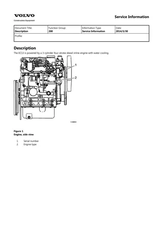
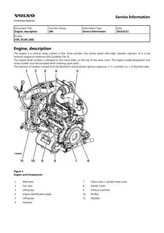
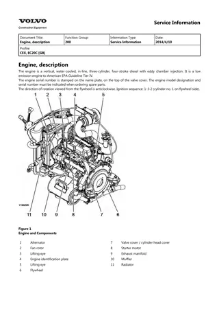
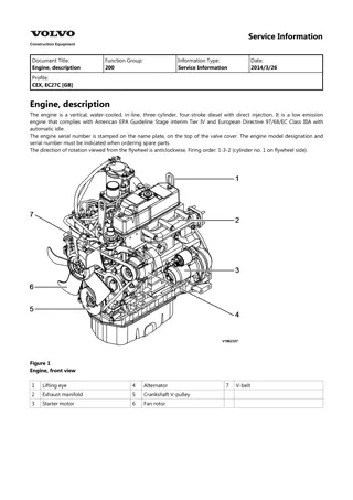
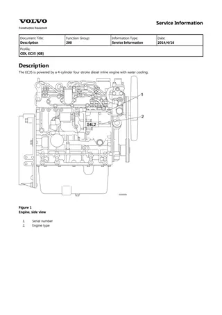
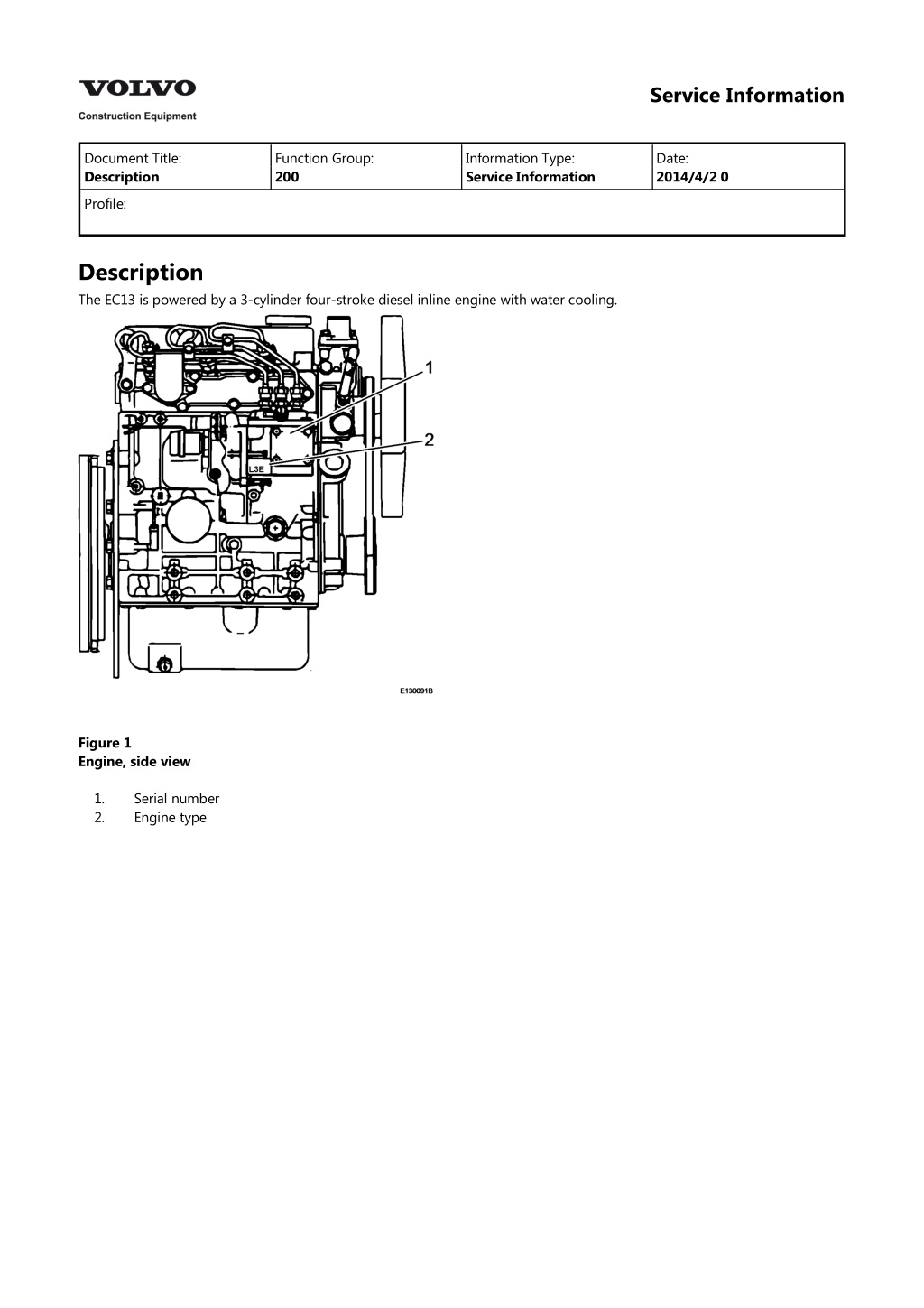
Service Information Document Title: Description Function Group: 200 Information Type: Service Information Date: 2014/4/2 0 Profile: Description The EC13 is powered by a 3-cylinder four-stroke diesel inline engine with water cooling. Figure 1 Engine, side view 1. 2. Serial number Engine type
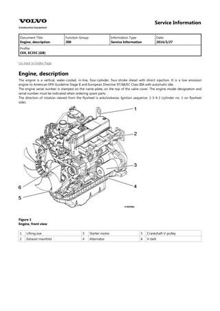
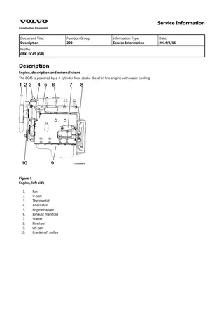
Figure 2 Left hand side view 1 Exhaust manifold 2 Starter 3 Oil sump 4 V-belt 5 Fan 6 Generator 7 Towing hook 8 Thermostat Figure 3 Right hand side view 1 Oil filler neck 2 Injection pump 3 Water pump 4 Oil filler neck 5 Crankshaft pulley 6 Oil filter 7 Oil drain plug 8 Oil dipstick 9 Flywheel 10 Coolant drain plug 11 Intake manifold 12 Injection nozzle
Service Information Document Title: Installing the engine Function Group: 200 Information Type: Service Information Date: 2014/4/2 0 Profile: Installing the engine Figure 1 Op nbr 2101 Lifting sling 1 m Shackle 3/8"" 1. Attach lifting tackle (1) to the engine. Weight approx. 125 kg. 2. Lift the engine into the machine. NOTE! Take care not to damage the hydraulic hoses. Figure 2 3. Cover the threads of screws (1) with screw retention agent, turn them into the rear and front engine mounts and tighten with 105 Nm. 4. Remove the lifting tackle to the engine.
https://www.ebooklibonline.com Hello dear friend! Thank you very much for reading. Enter the link into your browser. The full manual is available for immediate download. https://www.ebooklibonline.com
Figure 3 5. Connect electric cable (1) to the oil pressure switch. Figure 4 6. Assemble oil cooler and air baffle. 7. Assemble radiator (3) and fasten it with screws (1 and 2). Figure 5 8. Assemble top and bottom coolant hoses with new hose clamps (3). 9. Fasten fan grid (2) with screws (1).
Figure 6 10. Assemble compensation tank with hose. 11. Fasten suction hose (3) to the radiator with a new hose clamp (1). 12. Connect hose (1) to the hydraulic tank breather valve. Figure 7 13. Fasten the front ground strap (1) to the engine block. Figure 8 14. Assemble exhaust pipe (2) with a new clamp (1).
Figure 9 15. Install hydraulic pump (2), cover screws (1) with screw retention agent, turn them in and tighten with 105 Nm. Figure 10 16. Install the engine wiring loom and connect the following components: Thermal switch (1) Generator (2) Starter (3) Pre-heating system ( [Invalid linktarget] /1) Fasten the cables with cable straps. Figure 11 17. Attach throttle cable (3) to injection pump (4). 18. Adjust throttle cable (3) and fasten with counter nut (2). NOTE!
Check idle speed and full load stop positions. 19. Join electric plug connection (1) for engine shut-down together. Figure 12 20. Fasten fuel tank (2) with screw (1). NOTE! Ensure correct fit of the spacer. 21. Fasten the front tank fastening bracket with screw ( [Invalid linktarget] /1). Figure 13 22. Assemble reinforcement plate (3) with immobilizer control unit (2). 23. Join electric plug connections (1) together. Figure 14 24. Fasten the right hand reinforcement plate (4) with screw (3). 25. Attach bracket (2) and fasten it with screws (1) from both sides.
Figure 15 26. Push fuel lines (2) onto fuel sensor. 27. Push ventilation hose onto yoke. 28. Join electric plug connection (1) together. Figure 16 29. Assemble counterweight (2) and fasten with screws (1) on left and right hand side. 30. Insert the foam rubber wedge from underneath behind the right hand counter weight. Figure 17 31. Assemble air filter bracket (2) with air filterto bracket (3) and frame. 32. Fasten the air intake hose (2) with a new hose clamp to the air intake pipe. 33. Connect electric cables ( [Invalid linktarget] /1) to the air filter contamination indicator ( [Invalid linktarget] /2).
Figure 18 34. Fasten fuel pre-cleaner (2) with screw (3). 35. Set valve lever (1) to position OPEN. 36. Assemble fuel filter (4). 37. Assemble fuel supply and return lines. Figure 19 38. Attach compensation tank (2). 39. Fasten the cable set with new cable strap (1). 40. Close the drain plug ( [Invalid linktarget] /1) and fill in coolant. Filling capacity: approx. 5 litres Figure 20
NOTE! Insert the foam rubber on the right hand reinforcement plate. 41. Apply the right hand top side casing (2), plug in the electric plug connections, assemble the rubber grommet and fasten the side casing with screws (1). Figure 21 42. Insert the dozer blade control lever from outside, slide on pivot arm (2) and fasten with screw (1). NOTE! Insert the foam rubber on the left hand reinforcement plate. 43. Connect ground cable ( [Invalid linktarget] /1) to the battery. 44. Assemble the top left hand side casing. 45. Assemble carrier ( [Invalid linktarget] /3). 46. Insert the rubber grommet. 47. Insert switch ( [Invalid linktarget] /2) into the carrier and plug in the electric plug connections ( [Invalid linktarget] /1). Figure 22 48. Fasten the side casing with screws (2). 49. Assemble rubber handle (1) to the throttle control lever.
Figure 23 50. Fasten the tool box with screws (1). NOTE! Ensure correct fit of rubber grommet (2). 51. Assemble the seat with console ( [Invalid linktarget] ). 52. Assemble roll over protection structure ( [Invalid linktarget] and [Invalid linktarget] ). 53. Join electric plug connection ( [Invalid linktarget] /1) together. Figure 24 54. Assemble right and left hand side casings (2) with screws (1). Figure 25 55. Fasten the engine hood with screws (1) and align. 56. Assemble the floor plate.
57. Check engine oil level, top up if necessary 58. Start the engine and make sure that there are no leaks.
Service Information Document Title: Removing the engine Function Group: 200 Information Type: Service Information Date: 2014/4/2 0 Profile: Removing the engine Op nbr 2101 Lifting sling 1 m Shackle 3/8"" Figure 1 1. Unscrew fastening screws (1). 2. Take off the engine hood. 3. Disassemble the floor plate. Figure 2 4. Unscrew all screws (1) and remove lower right and left hand side casing (2).
Figure 3 5. Disconnect the electric plug connection (1). Figure 4 6. Unscrew the rear fastening screws (1) for the roll over protection structure. Figure 5 7. Attach the lifting sling to the lifting points of the roll over protection structure and lift the roll over protection structure until the ropes are tight. 8. Unscrew the front fastening screws. 9. Lift the roll over protection structure slightly up, make sure that the area around is safe and lift it off completely.
Figure 6 10. Raise the seat console at the front and lift out the driver s seat with the lifting tackle attached to the seat belt. Figure 7 11. Unscrew screws (1) and lift out the tool box. NOTE! Unhook the rubber grommet with wiring loom (2). Figure 8 12. Pull rubber handle (1) off the throttle control lever. 13. Unscrew all screws (2).
Figure 9 14. Push rubber grommet (1) away from the control lever. 15. Force switch carrier (2) out with a screw driver. Figure 10 16. Disconnect plug connections (1) from switches (2), take the switches out of carrier (3) and plug the plug connections back on. 17. Disassemble the top left hand side casing. Figure 11 WARNING Disconnect and connect the battery only with the ignition switched off. Disconnect the minus pole (green fastening) first. During assembly connect the plus pole (red cable) first. 18. Disconnect ground cable (1) from the battery.
Figure 12 19. Remove screw (1). 20. Pull off pivot arm (2) for dozer blade control lever. 21. Pull the control lever out sideways. Figure 13 22. Unscrew fastening screws (1), pull off electric plug connections, push the rubber grommet back off the control lever and remove the right hand side casing (2). Figure 14 23. Cut both cable straps (1). 24. Remove the compensation tank (2) from the holder.
25. Unscrew screws (3). Figure 15 26. Disconnect intake air hose (1) from the air intake pipe and close the opening on the engine with sticky tape. 27. Unscrew the screws from air filter bracket (2) on yoke (3). Figure 16 28. Set valve lever (1) on fuel filter (2) to position CLOSED. 29. Disconnect fuel supply and return lines. 30. Unscrew screw (3). 31. Detach fuel filter (4) and lay down to the side. WARNING Catch fuel running out and dispose of environmentally.
Suggest: If the above button click is invalid. Please download this document first, and then click the above link to download the complete manual. Thank you so much for reading
Figure 17 32. Pull electric cables (1) off the air filter contamination indicator (2). 33. Take off the complete air filter bracket. Figure 18 34. Pull electric plug connection (1) for fuel sensor apart. 35. Mark fuel hoses (2) and pull off fuel sensor, disconnect ventilation hose from yoke. 36. Close fuel hoses with plugs. 37. Cut the cable straps for the suction line to the fuel filter and lay the fuel filter to the side. Figure 19 38. Unscrew screws (1) and take off left and right hand counter weights (2). Figure 20
https://www.ebooklibonline.com Hello dear friend! Thank you very much for reading. Enter the link into your browser. The full manual is available for immediate download. https://www.ebooklibonline.com

