Understanding Kirchhoff's Rules for Circuit Analysis
Learn how to analyze complex circuits using Kirchhoff's rules which involve the junction rule and loop rule. Discover the lingo of circuits, apply the rules to solve circuits that can't be reduced, and understand how to assign currents in branches for circuit analysis. Explore examples and techniques for applying Kirchhoff's rules effectively.
Download Presentation

Please find below an Image/Link to download the presentation.
The content on the website is provided AS IS for your information and personal use only. It may not be sold, licensed, or shared on other websites without obtaining consent from the author. Download presentation by click this link. If you encounter any issues during the download, it is possible that the publisher has removed the file from their server.
E N D
Presentation Transcript
KIRCHHOFFS RULES
Todays objectives By the end of this lesson, you will be able to: Analyze a complex circuit using Kirchhoff s rules, using the conventions for determining the correct signs of various terms.
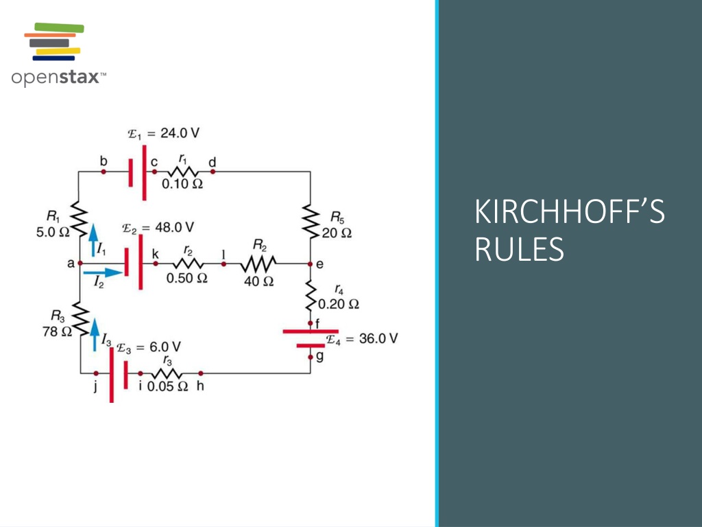
Lets start with some lingo: A junction is a point where three or more conductors meet. A branch is the path from one junction point to the other. A loop is any closed conducting path. Look at the circuits on the right, identify and count the junctions, branches, and loops. This circuit cannot be reduced to a combination of series and parallel connections. Kirchhoff s rules, special applications of the laws of conservation of charge and energy, can be used to analyze it. (Note: The script E in the figure represents electromotive force, emf.)
Kirchhoffs rules Kirchhoff s junction rule: The algebraic sum of the currents entering any junction must equal the algebraic sum of the currents leaving the junction : ???= ???? Kirchhoff s loop rule: The algebraic sum of the potential differences around any closed loop must equal zero: V = 0. Note: one of these rules is a conservation of energy and the other one is a conservation of charge. Which one is which? The junction rule. The diagram shows an example of Kirchhoff s first rule where the sum of the currents into a junction equals the sum of the currents out of a junction. In this case, the current going into the junction splits and comes out as two currents, so that ?1 = ?2 + ?3 . Here ?1 must be 11 A, since ?2 is 7 A and ?3 is 4 A.
Kirchhoffs rules, continued The loop rule. An example of Kirchhoff s second rule where the sum of the changes in potential around a closed loop must be zero. (a) In this standard schematic of a simple series circuit, the emf supplies 18 V, which is reduced to zero by the resistances, with 1 V across the internal resistance, and 12 V and 5 V across the two load resistances, for a total of 18 V. (b) This perspective view represents the potential as something like a roller coaster, where charge is raised in potential by the emf and lowered by the resistances. (Note that the script E stands for emf.)
How to apply Assign and label on a diagram a current for each branch of the circuit. Note: 1.One brunch = one current. 2.Do not worry about how you assign the directions of the currents! Apply junction rule: sum up the currents entering a junction and set it equal to the sum of the currents leaving the junction. The number of junction rule equations = number of junctions - 1
How to apply, continued Chose and label a direction of travel along a loop (clockwise or counterclockwise). Assign the potential differences to each element of a loop. Here is how (figure on the left). There is a logic behind these conventions think about it as going to a higher or lower potential. That makes it easier to remember, but not necessary you can simply memorize these. Each of these resistors and voltage sources is traversed from a to b. The potential changes are shown beneath each element and are explained in the text. (Note that the script E stands for emf.)
How to apply, continued Now is the time to apply that loop rule sum up all potential differences as you are traveling along a loop and set it equal to zero. How many loop equations do you need? In general, we need the total number of equations which equals to the number of unknown currents which, in turn, equals to the number of branches. So, write down the number of equations that you need to get that total. Rule of thumb we only add a new loop equation if the loop contains an element you have not used before in other loop equations.
Lets look at an example The circuit below has two junctions, three branches, and three loops. We need three equations in order to find three unknown currents. The chosen directions of the currents are absolutely arbitrary if you make an incorrect choice, the current will come out of the equations with a negative sign. We are ready to apply a junction rule (there will be just one of these here, since the total number of junctions is 2. For the junction labeled a: ?1= ?2+ ?3.
Example, continued Now we add two loop rules (since we need three equations all together). I start with the top loop and will travel in clockwise direction starting at junction a: I2R2+ 1 I2r1 I1R1= 0 Now let s travel counterclockwise along the bottom loop starting at junction a: 2 I3?2 I3?3 I1R1= 0 Note that we do not need the third loop since we already have the necessary number of equations.
Example, continued At this point we have three equations for three unknown currents. Typically, the resistances and emf s are given. You can use any of the tools you prefer to solve the system of linear equations to produce the solutions for the unknown currents. If the current is negative, the direction of the current is opposite to your original assumption. Once the currents are known, you can use Ohm s Law to find the potential differences, electrical power, etc.
Try it yourself Given the circuit below write the number of equations that would allow you to solve for the unknowns. You may go ahead and substitute the given numerical values to get the numerical solution.
