Electrical Circuit Analysis Examples and Solutions
Explore various examples of electrical circuit analysis involving batteries, resistors, and parallel connections. Learn how to calculate current, voltage, power dissipation, and equivalent resistance in different circuit configurations. Detailed solutions provided for better understanding.

Download Presentation

Please find below an Image/Link to download the presentation.
The content on the website is provided AS IS for your information and personal use only. It may not be sold, licensed, or shared on other websites without obtaining consent from the author.If you encounter any issues during the download, it is possible that the publisher has removed the file from their server.
You are allowed to download the files provided on this website for personal or commercial use, subject to the condition that they are used lawfully. All files are the property of their respective owners.
The content on the website is provided AS IS for your information and personal use only. It may not be sold, licensed, or shared on other websites without obtaining consent from the author.
E N D
Presentation Transcript
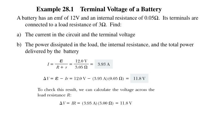
Example 28.1 Terminal Voltage of a Battery A battery has an emf of 12V and an internal resistance of 0.05 . Its terminals are connected to a load resistance of 3 . Find: a) The current in the circuit and the terminal voltage b) The power dissipated in the load, the internal resistance, and the total power delivered by the battery
Three resistors are connected in parallel as shown in Figure 28.7. A potential difference of 18 V is maintained between points a and b. (a) Find the current in each resistor. (b) Calculate the power delivered to each resistor and the total power delivered to the combination of resistors. 3
EX 6. Three resistors are connected in parallel as shown in Figure 28.11a. A potential difference of 18.0 V is maintained between points a and b. (A) Find the current in each resistor.
(B) Calculate the power delivered to each resistor and the total power delivered to the combination of resistors.
Find the currents I1 , I2 , and I3 in the circuit We arbitrarily choose the directions of the currents as labeled in Figure Substituting Equation (1) into Equation (2) gives Dividing each term in Equation (3) by 2 and rearranging gives Subtracting Equation (5) from Equation (4) eliminates I 2 , giving The fact that I 2 and I 3 are both negative indicates only that the currents are opposite the direction we chose for them. However, the numerical values are correct.


 Calculate the equivalent resistance of the circuit.")


 Calculate the power delivered to each resistor and the")