The Ignition System in Internal Combustion Engines
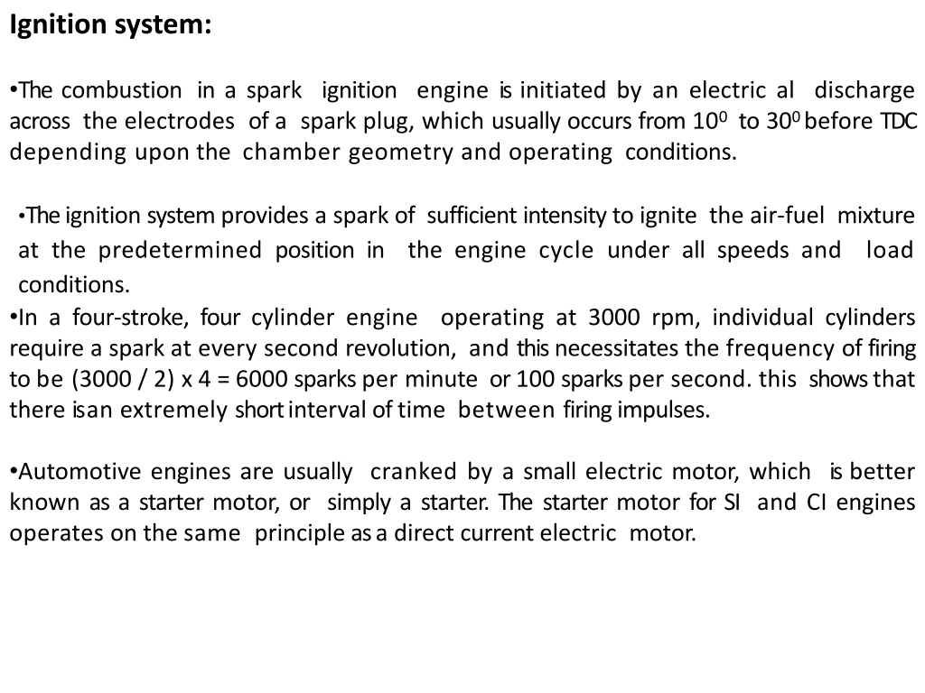

Ignition system:
•
The
combustion
in
a
spark
ignition
engine
is
initiated
by
an
electric
al discharge
across
the
electrodes
of
a
spark
plug,
which
usually
occurs
from
10
0
to
30
0
before
TDC
depending
upon
the
chamber
geometry and
operating
conditions.
•
The
ignition
system
provides
a
spark
of sufficient
intensity
to
ignite
the
air-fuel
mixture
at
the
predetermined
position
in
the
engine
cycle
under
all
speeds
and
load
conditions.
•
In
a
four-stroke,
four
cylinder
engine
operating
at
3000
rpm,
individual
cylinders
require
a
spark
at
every
second
revolution,
and
this
necessitates
the
frequency
of
firing
to
be
(3000
/
2)
x 4 =
6000
sparks
per
minute
or
100
sparks
per
second. this
shows
that
there
is
an
extremely
short
interval
of
time
between
firing
impulses.
•
Automotive
engines
are
usually
cranked
by
a
small
electric
motor,
which
is
better
known
as
a
starter
motor,
or
simply
a
starter.
The
starter
motor
for SI
and
CI
engines
operates
on
the
same
principle
as
a direct
current
electric
motor.

Modern ignition system:
•
T
h
e
d
e
v
e
l
o
p
m
e
n
t
o
f
h
i
g
h
speed, high
compression
internal
combustion
engine
requires
a
reliable
high-speed
ignition
system. This is
met
by
a
high-tension
ignition
system
that
uses
a
spark
plug
as
the
source
of
ignition.
The
electric
al
energy
to
the
spark
plug is
supplied
by
one
of
the
following
systems
and is
termed
accordingly.
1.
Battery ignition
system
2.
Magneto
ignition
system
3.
Electronic
ignition
system
1. Battery
ignition
system
•
The
primary
circuit
consists
of
the
battery,
ammeter,
ignition
switch,
primary
coil
winding,
capacitor,
and
breaker
points.
The
functions of
these
components
are:
Battery
:
provides
the
power
to
run
the
system.
Ignition
switch
:
allows
the
driver
to
turn
the
system
on
and
off .
Pr
i
m
a
r
y
coil
:
p
r
o
d
u
ce
s
t
h
e
ma
g
n
e
ti
c
fi
e
l
d
t
o
c
r
e
a
t
e
t
h
e
high
voltage
in
the
secondary
coil.
Breaker p
o
int
s
:
a
m
ech
a
n
i
c
a
l
s
w
i
t
c
h
t
h
a
t
a
c
t s
a
s
t
h
e
triggering
mechanism.
Capacitor
:
protects
the
points
from
burning
out.
Contact Breaker
: Breaking the primary circuiting of ignition coil.
Induction Coil
: induction coil is iron core wrapped with primary and secondary
windings.
•
The
secondary
circuit converts
magnetic
induction
into
high
voltage
electricity
to
jump
across
the
spark
plug
gap,
firing
the
mixture
at
the
right
time.
The
functions of
the
components
are:
2.Magneto
ignition
system:
•
The
high
powered,
high
speed
spark
ignition
engines
like aircraft,
sports
and
racing
cars
use
magneto
ignition
system.
The
basic
components
of
a
magneto
ignition
system
consist
of
a
magneto,
breaker
points,
capacitor,
ignition
switch,
distributor,
spark
plug
leads,
and
spark
plugs.
•
Magneto
can
either
be
rotating
armature
type
or
rotating
magneto
type.
In
the
former,
the
armature
consisting
of
the
primary
and
secondary
windings
all
rotate
between
the
poles
of
a
stationary
magneto,
while
in
the
second
type,
the
magneto
revolves
and
the
windings
are
kept
stationary.
Magneto
ignition
system
(with
rotating
magnets)
3. Electronic
ignition
system
•
The
disadvantage
of
the
mechanic
al
system
is
that
it
requires
regular
adjustment
to
compensate
for
wear,
and
the
opening
of
the
conta
ct
breakers,
which
is
responsible
for
spark
timing,
is
subject
to
mechanic
al
variations.
•
In
addition,
the
spark
voltage
is
also
dependent
on
conta
ct
effectiveness,
and
poor
sparking
may
lower
the
engine
efficiency.
Electronic
ignition
system
has
solved
these
problems.
•
In
this
system,
the
conta
ct
breaker
points
are
replaced
by
an
angular
sensor
of
some
kind
-
either
optical
,
where
a
vaned
rotor
breaks
a
light
beam,
or
more
commonly
using
a
hall effect
sensor,
which
responds
to
a
rotating
magnet
mounted
on a
suitable
shaft.
•
The
sensor
output
processed
by
a
suitable
circuitry
is
then
used
to
trigger
a
switching
device
such
as
a
thyristor
,
which
switches
a
large
flow
of
current
through
the
coil.
•
The
rest
of
the
system
(distributor
and
spark
plugs)
remains the
same
as
that
of
the
mechanic
al
system.
The
lack
of
moving
parts
compared
with
the
mechanic
al
system
leads
to
greater
reliability
and
longer
service
intervals.
In
some
older
cars,
it
was
usually
possible
to
retrofit
an
electronic
ignition
system
in
place
of
the
mechanic
al
one.
SPARK PLUG:
the spark plug is a part of the ignition system which sends high voltage into the
combustion chamber to create a spark which causes the compressed air fuel mixture
to burn.
the main parts are as follows:
1. Terminal:
the top of the spark plug contains a terminal which is connected to a high
tension wire through which high- current voltage current from the ignition system
flows.
2. Insulator:
the main function of the insulator is to provide the mechanical support
for the center electrode,( preventing escape of high voltage from the electrode).
•
The most widely used insulator is made of
aluminium ceramic
.
•
The aluminium ceramic offers high heat conduction ratio, electrical insulation,
corrosion resistance and durability against sudden cooling.
3. Steel shell
: the steel shell has threads that allow the spark plug to be tightened into
the combustion chamber and a hexagonal fitting is provided on the outside of the
shell.
4. Center electrode:
the center electrode is connected to the terminal through an
internal wire(resistor) .
•
The tip can be made of a
nickel alloy
containing very small amount of
manganese,
silicon and chrome.
5. Ground or side electrode:
the side electrode is made from high
nickel steel
and is
welded to the side of the steel shell.
•
The side electrode also runs very hot, especially on projected nose plugs.
6. Seal:
the spark plug mounted in the combustion chamber is subjected to extremely
high pressures.
•
The seal ensure that there is no leakage from the combustion chamber.
BATTERY:
•
A battery in automobiles is an electrical device which produces electricity(current)
through chemical action inside it.
•
The battery does not store electricity as electrons but stores as in the chemical form.
•
The electrical energy produced in the battery by the chemical reaction that occurs
between two dissimilar plates that are immersed in an electrolyte solution.
•
The automotive batteries are rechargeable, they can also convert an electrical current
into chemical energy and stores that energy until it is needed.
TYPES OF BATTERIES:
The following four types of batteries are used in automobiles:
1.
Lead- acid battery
2.
Alkaline- battery, which may be
i)
Nickel-iron type, ii)nickel-cadmium type and iii) silver-zinc type
3) Non- conventional battery which may be
i)Zinc-air battery, ii) sodium-sulphur type and lithium- chlorine type
4) Dry charge battery.
CONSTRUCTION OF BATTERY:
1. Battery Box:
battery box is made of hard rubber having inside three or six cell
compartments.
•
The capacity of the each cell is 2 volts.
•
The bunch of battery plates having positive and negative plates are separators and
place in compartments.
•
Then by placing cover it is covered by
cell cover.
This cover has three holes for
negative, positive and third for vent plug.
2. Battery plates:
Each cell has set of positive and negative plates and each are
separated by separator.
•
There is one more plate of negative than positive in each cell.
•
These plates are made of
lead
in the form of grids.
•
Positive plates
lead peroxide (
PbO
2
)
is
pasted and has
chocolate color
while negative
plate
lead antimony
is pasted and of
grey color.
3. separator:
separators are placed
in between negative and positive plates.
•
Separators made of wood or plastic are place so that plates should not touch each
other.
4. Electrolyte:
it is made 64% of
distilled water(H
2
O)
and 36% of
sulphuric acid
(H
2
SO
4
).
5. Vent Plug:
when battery charge or discharge then chemical action takes place and
gases formed and to release the gases a small holes are made in it.
•
Charging system:
The automotive storage battery is not capable of supplying the
current for a long period of times, as per demand of electrical system. Thus every
vehicle is equipped with a charging system.
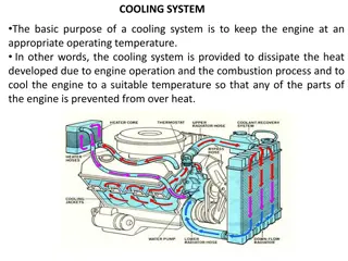
•
The basic purpose of the charging system is to convert the mechanical energy into
electrical(electricity) energy to recharge the battery and to operate the other
electrical systems.
The following main component are consist in charging system:
1.
Battery:
the charging system supplies direct current to the battery for charging.
•
During charging, the battery changes electrical energy from the generator into
chemical energy. The active materials of the battery are stored.
•
The battery also act as a shock absorber or voltage stabilizer in the system to
prevent damage to sensitive components in the electrical vehicles electrical
system.
2.
Generator:
It is the most important component of the charging system. It converts
mechanical energy from engine into electrical energy.
•
The mechanical energy is transferred from the engine to generator by grooved
drive on a pulley arrangement.
•
When rotated , it generates electricity by electromagnetic induction.
3.
Drive belt:
the generator is driven from the engine by means of a drive belt.
4.
Voltage regulator:
It controls the amount of electrical energy produced.
•
Without a regulator the generator will always operate at its highest output.
•
This may damage certain components and overcharge the battery.
•
The regulator controls the generator output to prevent overcharging or
undercharging.
5. Charging indicator( lamp or gauge):
It indicates whether the system is being
charged or not.
•
The charging indicator device most commonly used as simple on/off warning lamp.
•
It is normally “off”, it lights when the ignition is turned “on” for a check of the lamp
circuit.
6. Ignition switch:
It is used for starting the engine. When the ignition switch is in on
position, battery current energizes the generator.
STARTING SYSTEM:
•
The internal combustion engine used in automobile is not capable of self starting.
•
The starting system rotates the engine until it can continue itself.
•
The starting system is a combination of mechanical and electrical parts that work together to
start the engine.
•
the starting system is design to convert electrical energy from battery into mechanical energy
in the starting motor.
•
This motor then transfers the mechanical energy, through gears, to the flywheel on the
engines crankshaft.
The basic starting system consists of the following parts:
1. Battery, 2. Ignition switch, 3. Magnetic switch( either an electrical relay or a solenoid),
4. Starter motor, 5. Safety switch.
LIGHTING SYSTEM:
The ignition system in spark ignition engines initiates combustion through electric discharge across the spark plug electrodes. It ensures proper ignition timing for efficient engine operation at various speeds and loads. Modern ignition systems include battery, magneto, and electronic ignition types, each serving the critical function of generating sparks to ignite the air-fuel mixture. Components like coils, capacitors, and breaker points work together to create high-voltage electricity needed for combustion.

Uploaded on Sep 19, 2024 | 0 Views
Download Presentation

Please find below an Image/Link to download the presentation.
The content on the website is provided AS IS for your information and personal use only. It may not be sold, licensed, or shared on other websites without obtaining consent from the author.If you encounter any issues during the download, it is possible that the publisher has removed the file from their server.
You are allowed to download the files provided on this website for personal or commercial use, subject to the condition that they are used lawfully. All files are the property of their respective owners.
The content on the website is provided AS IS for your information and personal use only. It may not be sold, licensed, or shared on other websites without obtaining consent from the author.
E N D
Presentation Transcript
Ignition system: The combustion in a spark ignition engine is initiated by an electric al discharge across the electrodes of a spark plug, which usually occurs from 100 to 300 before TDC depending upon the chamber geometry and operating conditions. The ignition system provides a spark of sufficient intensity to ignite the air-fuel mixture at the predetermined position in the engine cycle under all speeds and load conditions. In a four-stroke, four cylinder engine operating at 3000 rpm, individual cylinders require a spark at every second revolution, and this necessitates the frequency of firing to be (3000 / 2) x 4 = 6000 sparks per minute or 100 sparks per second. this shows that there is an extremely short interval of time between firing impulses. Automotive engines are usually cranked by a small electric motor, which is better known as a starter motor, or simply a starter. The starter motor for SI and CI engines operates on the same principle as a direct current electric motor.
Modern ignition system: The development of high speed, high compression internal combustion engine requires a reliable high-speed ignition system. This is met by a high-tension ignition system that uses a spark plug as the source of ignition. The electric al energy to the spark plug is supplied by one of the following systems and is termed accordingly. Battery ignition system Magneto ignition system Electronic ignition system 1. 2. 3.
The primary circuit consists of the battery, ammeter, ignition switch, primary coil winding, capacitor, and breaker points. The functions of these components are: Battery : provides the power to run the system. Ignition switch : allows the driver to turn the system on and off . Primary coil : produces the secondary coil. the magnetic field to create the high voltage in Breaker points : a mechanic al switch that act s as the triggering mechanism. Capacitor :protects the points from burning out. Contact Breaker : Breaking the primary circuiting of ignition coil. Induction Coil : induction coil is iron core wrapped with primary and secondary windings.
The secondary circuit converts magnetic induction into high voltage electricity to jump across the spark plug gap, firing the mixture at the right time. The functions of the components are: Secondary coil : the part of the coil that creates the high voltage electricity Coil wire : a highly insulated wire to take the high voltage to the distributor cap : a plastic cap which goes on top of the distributor, to hold the high tension wires in the right order : spins around on the top of the distributor shaft, and distributes the spark to the right spark plug : another highly insulated wire that takes the high voltage from the cap to theplugs : take the electricity from the wires, and give it an air gap in the combustion chamber to jump across, mixture Distributor cap Rotor Spark leads Spark plugs plug to light the
2.Magneto ignition system: The high powered, high speed spark racing cars use magneto ignition system. The basic components of a magneto ignition system consist of a magneto, breaker points, capacitor, ignition switch, distributor,spark plug leads, and spark plugs. ignition engines like aircraft, sports and Magneto can either be rotating armature type or rotating magneto type. In the former, the armature consisting of the primary and secondary windings all rotate between the poles of a stationary magneto, while in the second type, the magneto revolves and the windingsare kept stationary.
Magneto ignition system (with rotating magnets)
Aspect Source of energy Battery ignition system Conservation chemical energy into electrical energy Magneto ignition system Conservation of kinetic energy into electrical energy Primary current starting Obtained from battery Obtained from magnet Easy start, because battery gives good spark Good spark, thus no problem Poor spark at start & lower speed of engine Poor spark at lower speed, thus engine runs erratically Low speed High speed Current for spark decrease as engine speed increased Current for spark increases with speed of engine, thus excellent spark at high speed System is light weight and compact, thus less space is required Very less and cheap maintenance, due to absence of battery Two wheelers scooters, racing cars, air craft etc., Space required System is bulky and require more space maintenance System requires more maintenance and it difficult to start engine when battery is in discharged In cars, light commercial vehicles Application
The disadvantage of the mechanic al system is that it requires regular adjustment to compensate for wear, and the opening of the contact breakers, which is responsible for spark timing, is subject to mechanic al variations. In addition, the spark voltage is also dependent on contact effectiveness, and poor sparking may lower the engine efficiency. Electronic ignition system has solved these problems. In this system, the contact breaker points are replaced by an angular sensor of some kind - either optical, where a vaned rotor breaks a light beam, or more commonly using a hall effect sensor, which responds to a rotating magnet mounted on a suitable shaft. The sensor output processed by a suitable circuitry is then used to trigger a switching device such as a thyristor, which switches a large flow of current through the coil. The rest of the system (distributor and spark plugs) remains the same as that of the mechanic al system. The lack of moving parts compared with the mechanic al system leads to greater reliability and longer service intervals. In some older cars, it was usually possible to retrofit an electronic ignition system in place of the mechanic al one.
SPARK PLUG: the spark plug is a part of the ignition system which sends high voltage into the combustion chamber to create a spark which causes the compressed air fuel mixture to burn. the main parts are as follows: 1. Terminal: the top of the spark plug contains a terminal which is connected to a high tension wire through which high- current voltage current from the ignition system flows. 2. Insulator: the main function of the insulator is to provide the mechanical support for the center electrode,( preventing escape of high voltage from the electrode). The most widely used insulator is made of aluminium ceramic. The aluminium ceramic offers high heat conduction ratio, electrical insulation, corrosion resistance and durability against sudden cooling. 3. Steel shell: the steel shell has threads that allow the spark plug to be tightened into the combustion chamber and a hexagonal fitting is provided on the outside of the shell. 4. Center electrode: the center electrode is connected to the terminal through an internal wire(resistor) . The tip can be made of a nickel alloy containing very small amount of manganese, silicon and chrome.
5. Ground or side electrode: the side electrode is made from high nickel steel and is welded to the side of the steel shell. The side electrode also runs very hot, especially on projected nose plugs. 6. Seal: the spark plug mounted in the combustion chamber is subjected to extremely high pressures. The seal ensure that there is no leakage from the combustion chamber.
BATTERY: A battery in automobiles is an electrical device which produces electricity(current) through chemical action inside it. The battery does not store electricity as electrons but stores as in the chemical form. The electrical energy produced in the battery by the chemical reaction that occurs between two dissimilar plates that are immersed in an electrolyte solution. The automotive batteries are rechargeable, they can also convert an electrical current into chemical energy and stores that energy until it is needed. TYPES OF BATTERIES: The following four types of batteries are used in automobiles: 1. Lead- acid battery 2. Alkaline- battery, which may be i) Nickel-iron type, ii)nickel-cadmium type and iii) silver-zinc type 3) Non- conventional battery which may be i)Zinc-air battery, ii) sodium-sulphur type and lithium- chlorine type 4) Dry charge battery.
CONSTRUCTION OF BATTERY: 1. Battery Box: battery box is made of hard rubber having inside three or six cell compartments. The capacity of the each cell is 2 volts. The bunch of battery plates having positive and negative plates are separators and place in compartments. Then by placing cover it is covered by cell cover. This cover has three holes for negative, positive and third for vent plug. 2. Battery plates: Each cell has set of positive and negative plates and each are separated by separator. There is one more plate of negative than positive in each cell. These plates are made of lead in the form of grids. Positive plates lead peroxide (PbO2)is pasted and has chocolate color while negative plate lead antimony is pasted and of grey color. 3. separator: separators are placedin between negative and positive plates. Separators made of wood or plastic are place so that plates should not touch each other. 4. Electrolyte: it is made 64% of distilled water(H2O) and 36% of sulphuric acid (H2SO4). 5. Vent Plug: when battery charge or discharge then chemical action takes place and gases formed and to release the gases a small holes are made in it.
Charging system: The automotive storage battery is not capable of supplying the current for a long period of times, as per demand of electrical system. Thus every vehicle is equipped with a charging system. The basic purpose of the charging system is to convert the mechanical energy into electrical(electricity) energy to recharge the battery and to operate the other electrical systems.
The following main component are consist in charging system: 1. Battery: the charging system supplies direct current to the battery for charging. During charging, the battery changes electrical energy from the generator into chemical energy. The active materials of the battery are stored. The battery also act as a shock absorber or voltage stabilizer in the system to prevent damage to sensitive components in the electrical vehicles electrical system. 2. Generator: It is the most important component of the charging system. It converts mechanical energy from engine into electrical energy. The mechanical energy is transferred from the engine to generator by grooved drive on a pulley arrangement. When rotated , it generates electricity by electromagnetic induction. 3. Drive belt: the generator is driven from the engine by means of a drive belt. 4. Voltage regulator: It controls the amount of electrical energy produced. Without a regulator the generator will always operate at its highest output. This may damage certain components and overcharge the battery. The regulator controls the generator output to prevent overcharging or undercharging.
5. Charging indicator( lamp or gauge):It indicates whether the system is being charged or not. The charging indicator device most commonly used as simple on/off warning lamp. It is normally off , it lights when the ignition is turned on for a check of the lamp circuit. 6. Ignition switch: It is used for starting the engine. When the ignition switch is in on position, battery current energizes the generator.
STARTING SYSTEM: The internal combustion engine used in automobile is not capable of self starting. The starting system rotates the engine until it can continue itself. The starting system is a combination of mechanical and electrical parts that work together to start the engine. the starting system is design to convert electrical energy from battery into mechanical energy in the starting motor. This motor then transfers the mechanical energy, through gears, to the flywheel on the engines crankshaft. The basic starting system consists of the following parts: 1. Battery, 2. Ignition switch, 3. Magnetic switch( either an electrical relay or a solenoid), 4. Starter motor, 5. Safety switch.


:It indicates whether")